 12
12
InWin 309 Review
Assembly, Finished Looks & GLOW2 Software »A Closer Look - Inside
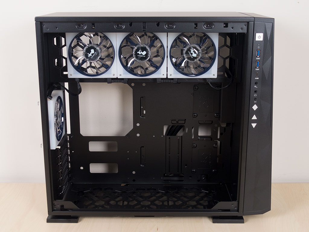
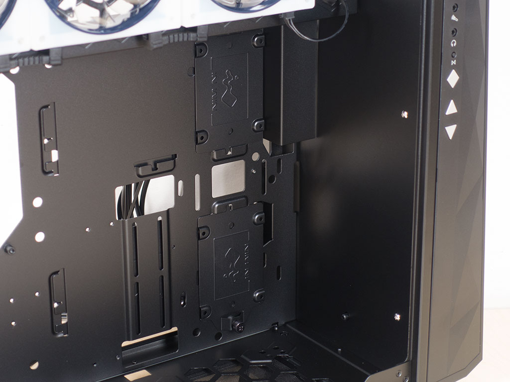
To access the interior simply release the latch on the glass panel and remove the two thumb screws holding the solid side in place. On the interior, things look very simple. There are no rubber grommets, no well-placed and rubber-grommet-covered cable-routing holes or cable channels. In Win has included some holes, so you will be able to route everything, but the end result won't be as pretty as with most other cases out there.
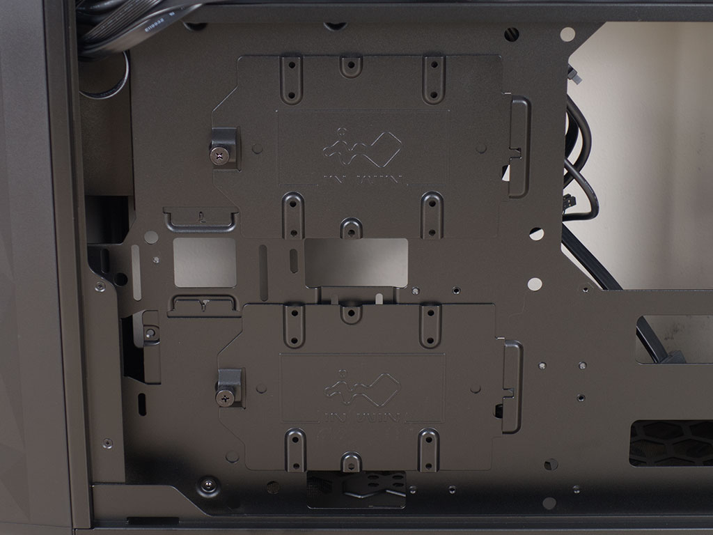
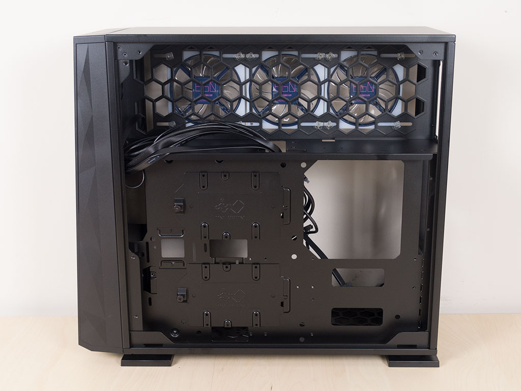
Behind the motherboard tray are two sturdy solid trays which are held in place by a single thumb screw, each. These allow for either a 2.5" or 3.5" drive to be installed.
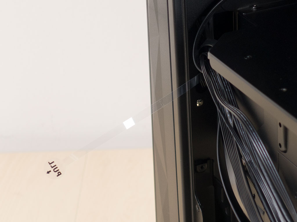
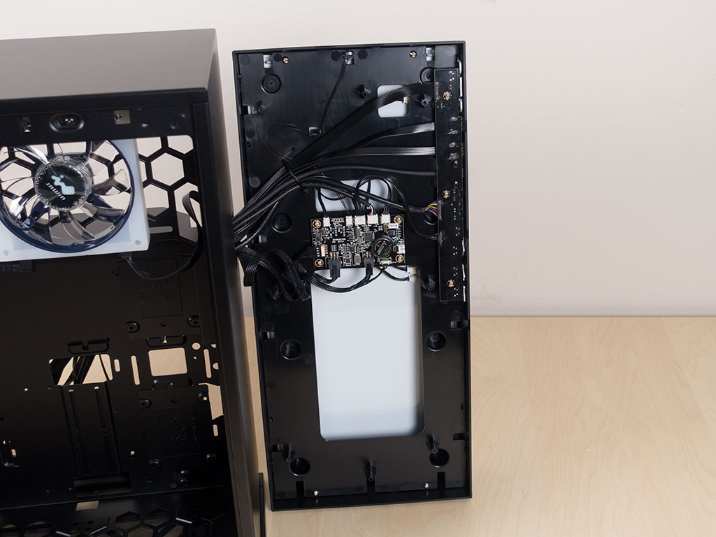
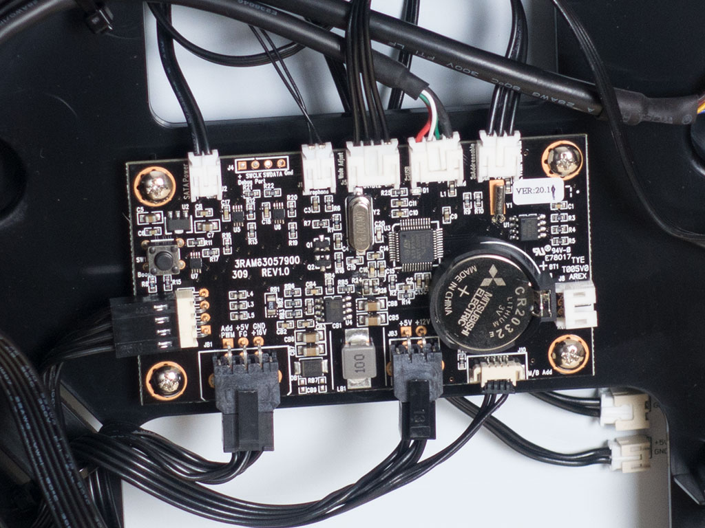
The first thing you will probably notice on the main side when opening the case is a pull tab. It acts as a barrier, so the embedded battery in the front cover won't drain while the case is waiting to be sold. I must have yanked it too hard as I managed to pop out the battery inside the cover in the process. Luckily, six removed screws later, I was able to access the interior. Most of the thickness of the front panel is taken up by the 144 LED array, but the brains of the whole thing is right in the middle. The battery is needed so your software settings aren't lost every time you turn off your system.
In the interior, the whole front is completely solid. It looks like there is plenty of missed potential to allow for additional storage here, or specific mounting possibilities for pumps and reservoirs.
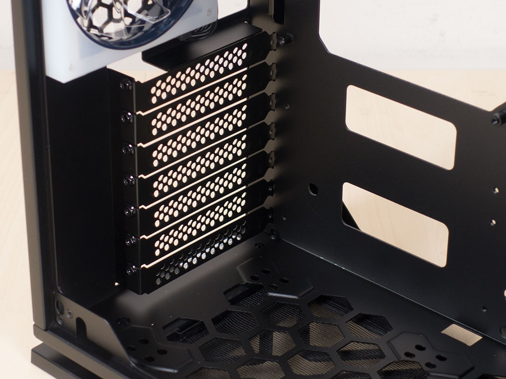
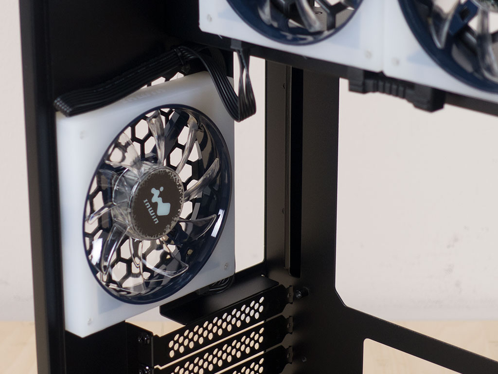

The bottom third of the rear is taken up by the seven expansion slots. Interestingly enough, InWin has chosen to use classic screws instead of thumb screws to hold the covers in place. Judging by the placement of the bottom expansion slot, an ATX board is going to be a tight fit. Above that is the rear 120 mm EGO fan; it looks pretty awesome. The silicone frame acts as a defusing element for the embedded aRGB LEDs and an anti-vibration element. Naturally, due to the soft material, you can't use screws to hold it in place, so InWin employs plastic pins, which do the job just fine. In the very top is the PSU bay, which is accessible from behind the motherboard, so you won't really see it in the final build.
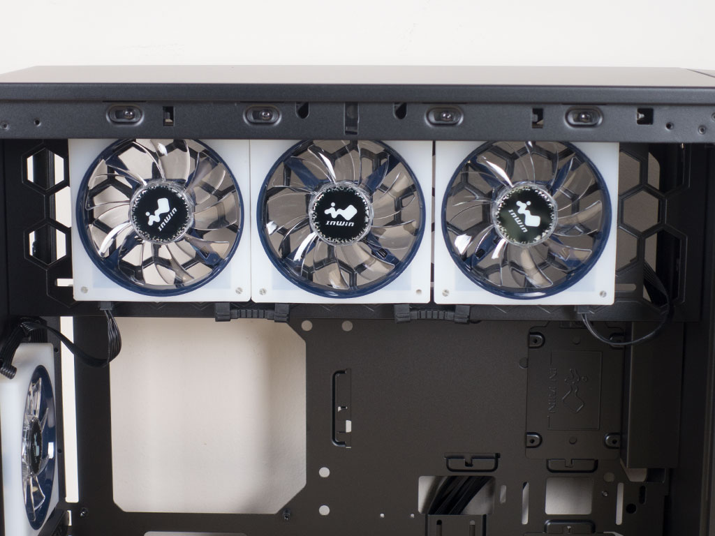
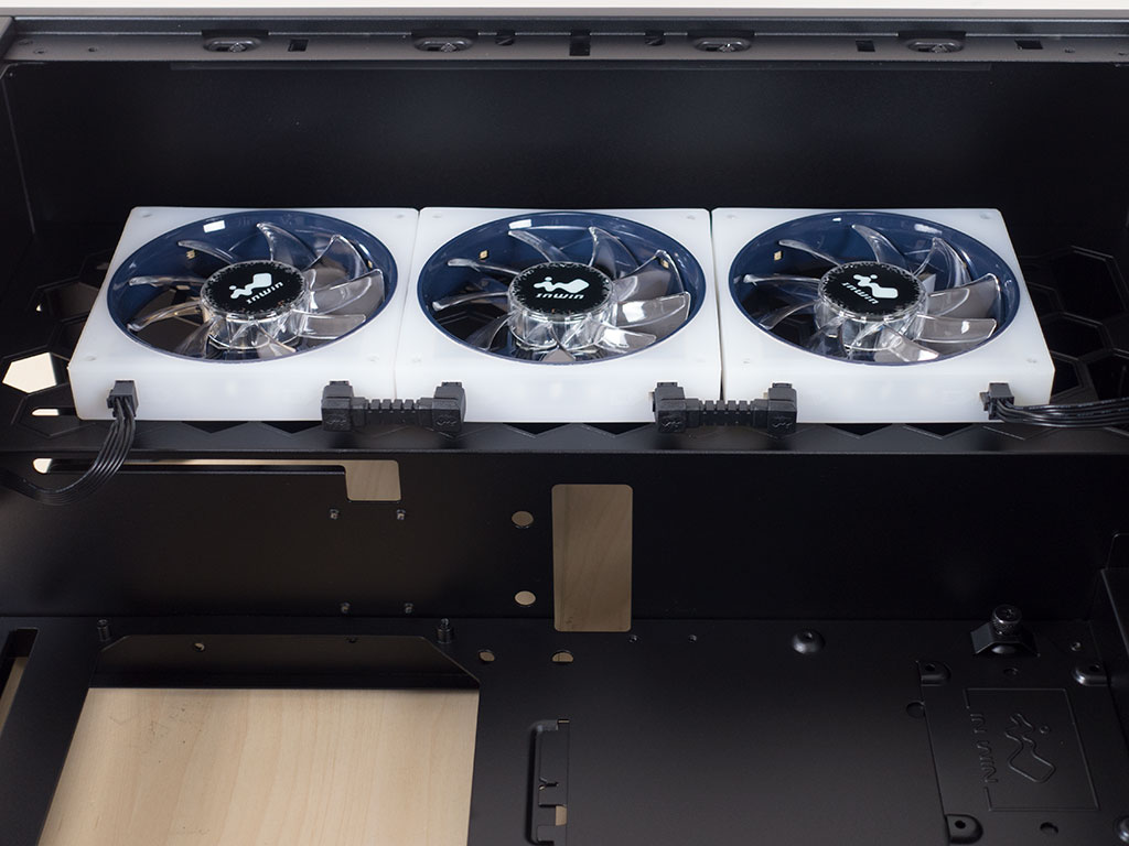
On the other side of that bay are three more 120 mm EGO fans. InWin designed their own interconnects as well, and pre-wired all four supplied units perfectly. While each unit is held in place by the plastic pins, one fan was missing in our review unit, which can be chalked up to human error at the factory.
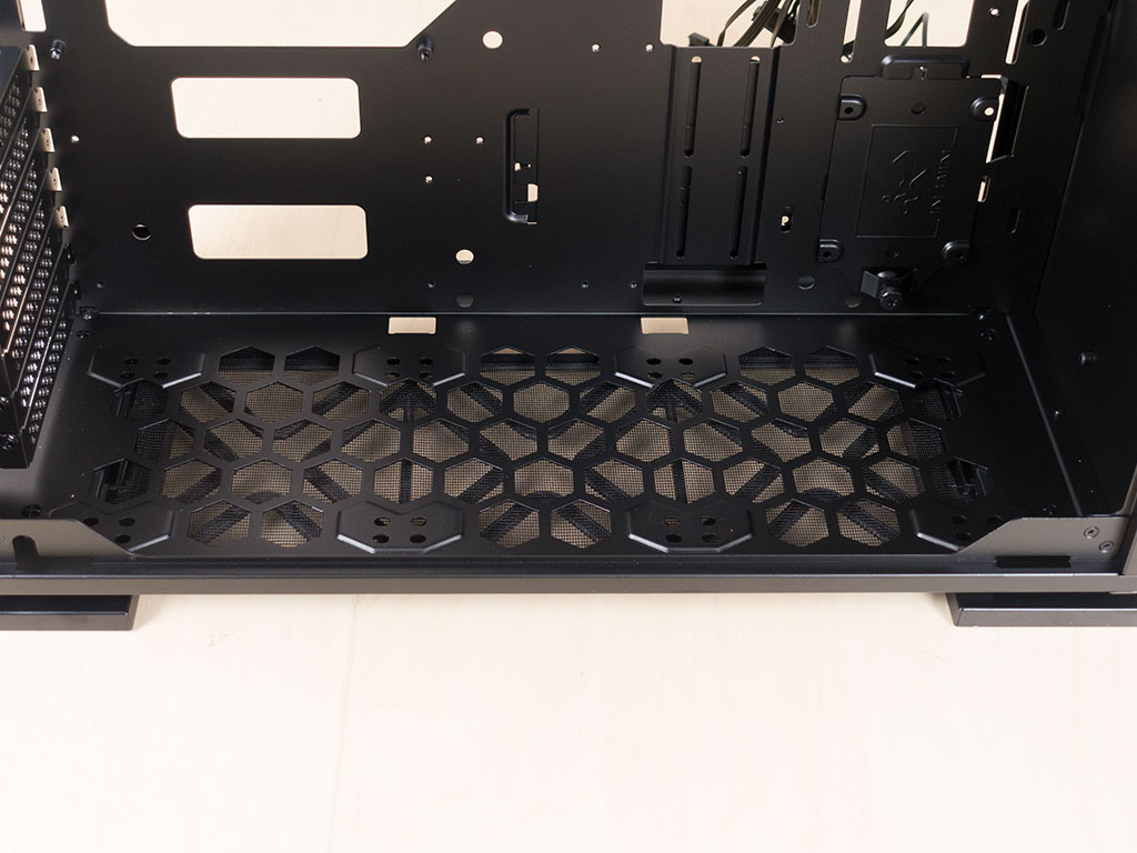
With the front not being able to accommodate additional cooling, InWin has turned to the flooring, where you may install three 120 mm fans or even go for a 360 mm radiator, which will also be possible if you use an ATX board and connect everything before installing such a cooling element here. However, I would suggest focusing on a good mATX board instead, which not only gives you some breathing room, but access to additional cable-routing holes. So while the InWin 309 is fine with an ATX board, the best compromise is mATX.
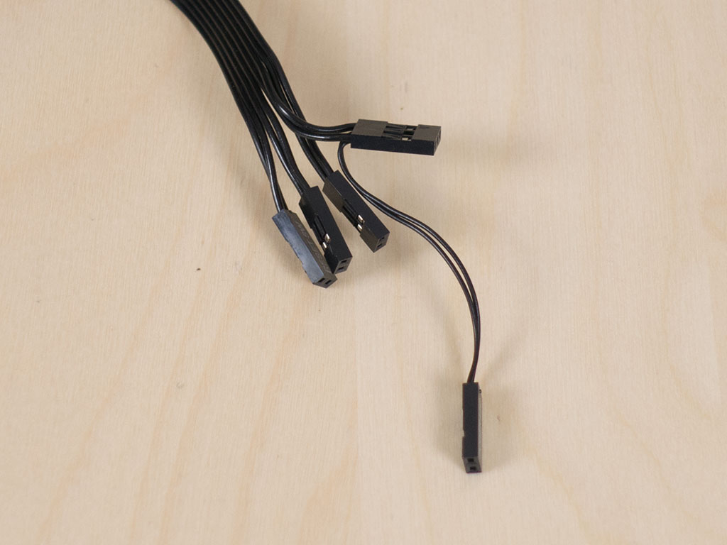
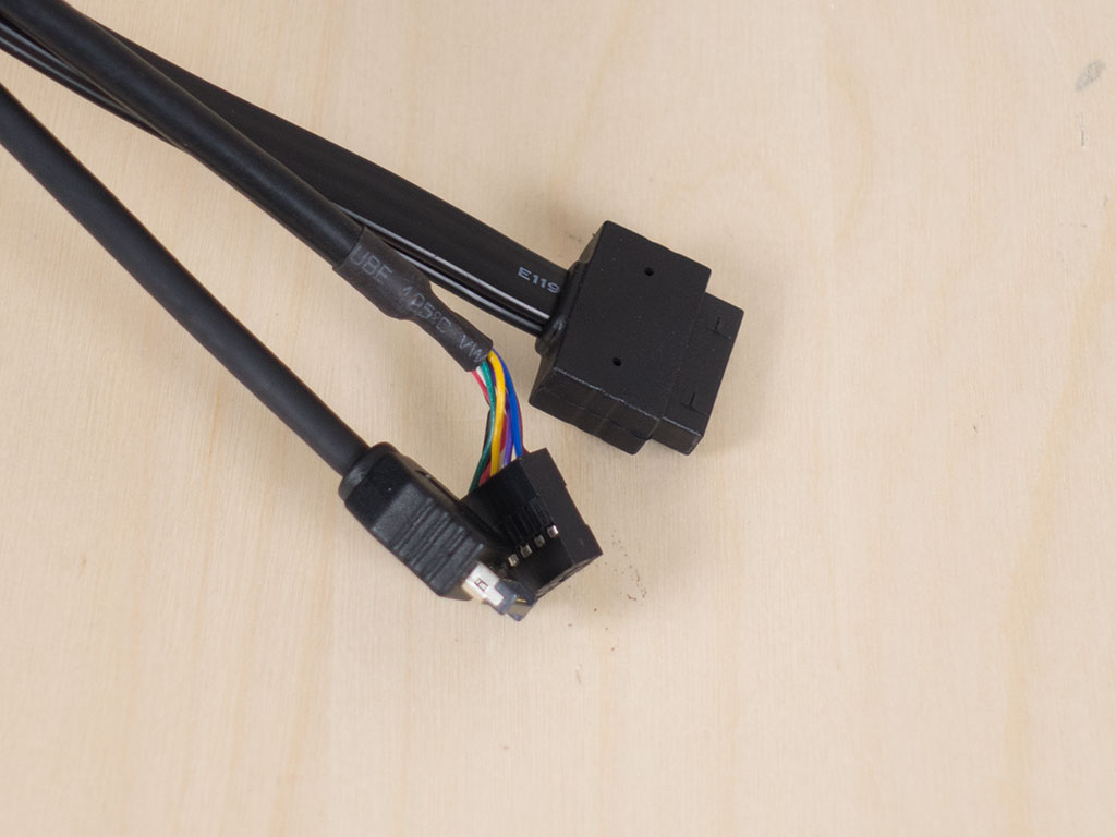
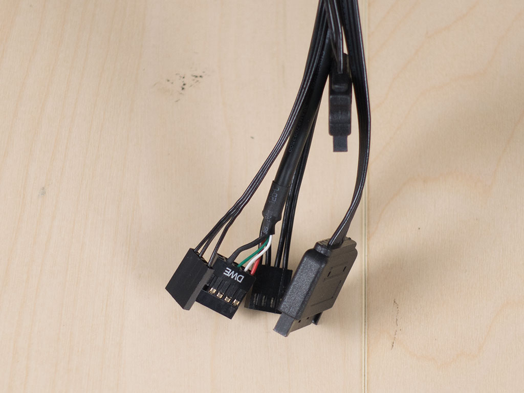
All the cables within the InWin 309 are sleeved black and of the default variety when it comes to the I/O and basic case elements. On a small downside, the HDD and power LED cables aren't market with +/-, so you have to trial of error here to get it right. For the LED panel and the controller, you will find two additional SATA power leads and a USB 2.0 connector to allow the GLOW2 software to access the control unit in Windows. On top of that, you will find a single PWM fan connector and a 3-pin RGB plug, which means you are free to choose whether the embedded LEDs and fan speeds are to be controlled by the motherboard or the GLOW2 software.
Apr 8th, 2025 05:29 EDT
change timezone
Latest GPU Drivers
New Forum Posts
- is it worth using ssd with usb2? (13)
- Is RX 9070 VRAM temperature regular value or hotspot? (330)
- RX 9000 series GPU Owners Club (238)
- 5070 cards available below £550 in in the UK (76)
- 9070XT or 7900XT or 7900XTX (130)
- The easiest way to connect the BOOTSEL test metal terminal and the GND terminal.... (2)
- gpu heirarchy/performance/benchmarks- whos lying? (67)
- Sapphire NITRO+ RX 5700 XT BE original BIOS request (11)
- No idea how many watts this USB-C port will supply? (10)
- The coffee and tea drinkers club. (250)
Popular Reviews
- The Last Of Us Part 2 Performance Benchmark Review - 30 GPUs Compared
- UPERFECT UStation Delta Max Review - Two Screens In One
- PowerColor Radeon RX 9070 Hellhound Review
- ASUS Prime X870-P Wi-Fi Review
- Upcoming Hardware Launches 2025 (Updated Apr 2025)
- MCHOSE L7 Pro Review
- Sapphire Radeon RX 9070 XT Pulse Review
- Corsair RM750x Shift 750 W Review
- Sapphire Radeon RX 9070 XT Nitro+ Review - Beating NVIDIA
- DDR5 CUDIMM Explained & Benched - The New Memory Standard
Controversial News Posts
- NVIDIA GeForce RTX 5060 Ti 16 GB SKU Likely Launching at $499, According to Supply Chain Leak (161)
- MSI Doesn't Plan Radeon RX 9000 Series GPUs, Skips AMD RDNA 4 Generation Entirely (146)
- Microsoft Introduces Copilot for Gaming (124)
- AMD Radeon RX 9070 XT Reportedly Outperforms RTX 5080 Through Undervolting (119)
- NVIDIA Reportedly Prepares GeForce RTX 5060 and RTX 5060 Ti Unveil Tomorrow (115)
- Over 200,000 Sold Radeon RX 9070 and RX 9070 XT GPUs? AMD Says No Number was Given (100)
- NVIDIA GeForce RTX 5050, RTX 5060, and RTX 5060 Ti Specifications Leak (97)
- Nintendo Switch 2 Launches June 5 at $449.99 with New Hardware and Games (92)