 11
11
NZXT HALE90 750 W Review
Voltage Regulation & Efficiency »A Look Inside
Before reading this page we strongly suggest to take a look at this article, which will help you understand the internal components of a PSU much better.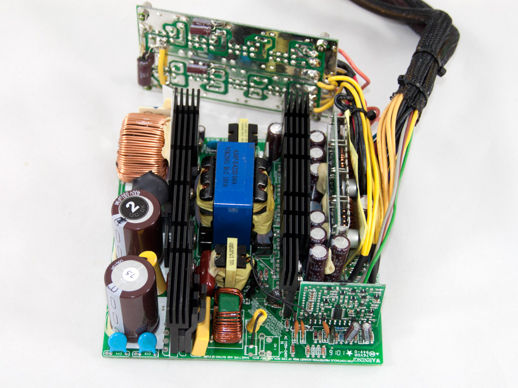

The OEM of the PSU is Super Flower and an LLC resonant topology is used to achieve Gold level efficiency. As you can see in the above pictures there are no toroidal coils in the secondary side, since this topology does not require any.
The first stage of the transient filter starts, as usual, at the AC receptacle and consists of one X and two Y capacitors and a coil. It continues to the main PCB with one X, two Y caps and a coil. Unfortunately, although there is room for it, no MOV (Metal Oxide Varistor) is available. A very serious omission that leaves the PSU and consequently the whole system unprotected from spikes coming from the power grid. The single bridge rectifier is sandwiched between two heatsinks.


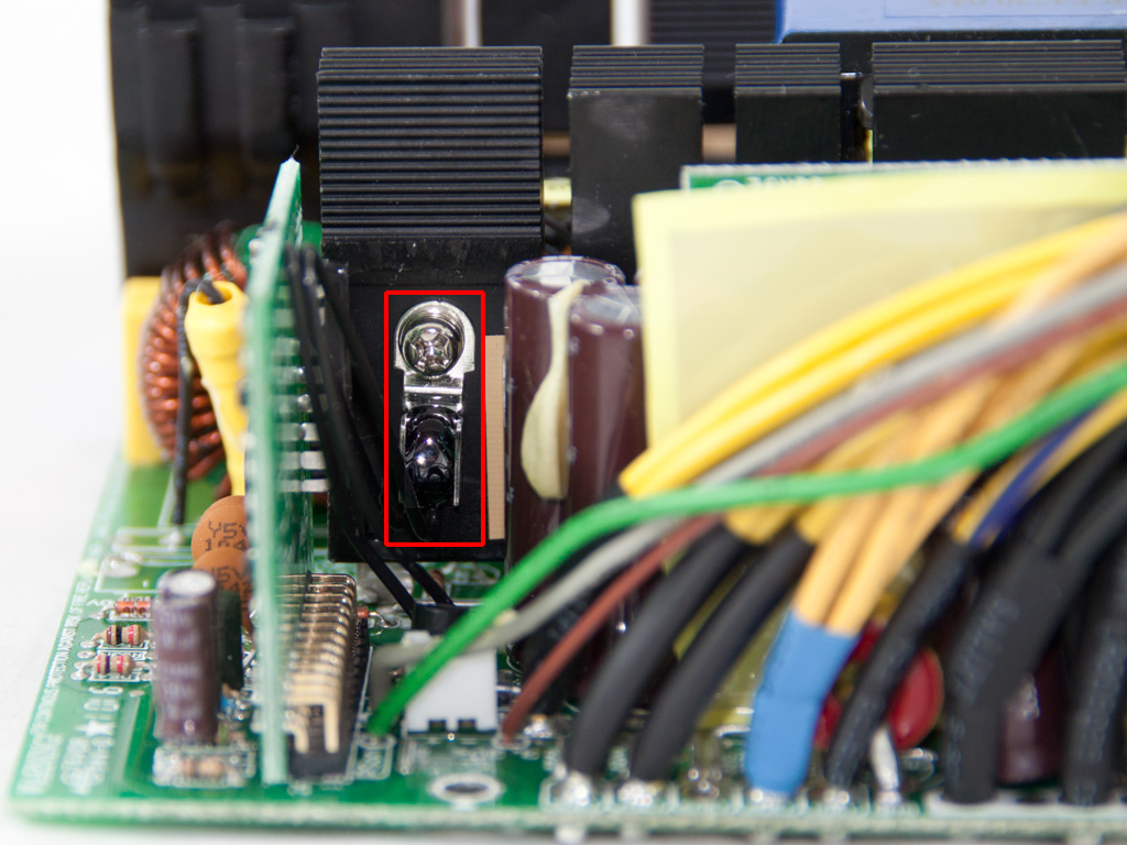
In the APFC stage two IPW60R125CP are used along with a boost diode. Also two parallel capacitors are used for smoothing/energy reservoir purposes. They are provided by Nippon Chemi-Con (KMQ series, 105°C, 330μF, 400V). Near the middle capacitor resides an electromagnetic relay along with a thermistor that provides protection against large inrush currents. The relay bypasses the thermistor, to save energy and allow its fast cool-down, once the PSU starts and the APFC capacitors are fully charged. The PFC controller is an NCP1653A IC which is housed on a vertical daughter-board right next to the PFC choke. As primary switches we find two IPW50R140P mosfets.
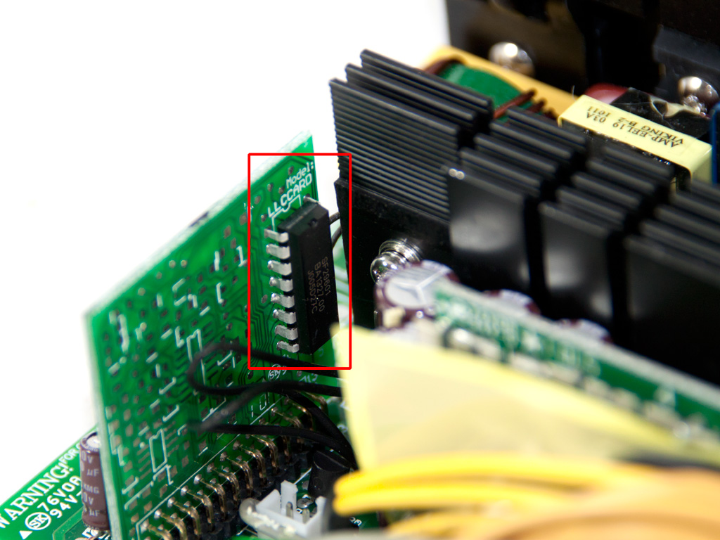
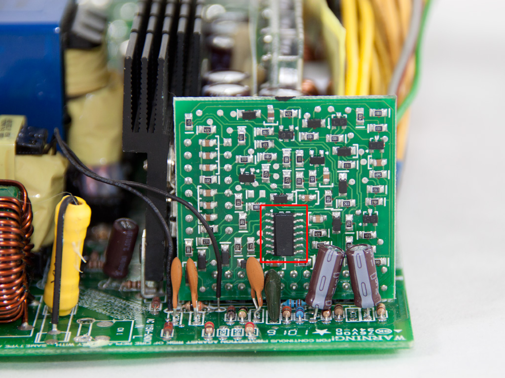
The LLC resonant controller for the primary switches is on a daughter-board residing in the secondary side. Its model number is SF29601 and we didn't find any bibliography about this IC on the net. Besides the role of LLC resonant controller it must do some house keeping too (meaning it incorporates some of the PSU's protections) because on the rear side of the same daughter-board we found an LM324 quad operation amplifier.
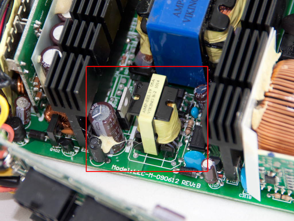
The 5VSB rail is filtered by a Nippon Chemi-Con cap (KZE series, 105°C) and the standby PWM controller is an ICE3B0565.

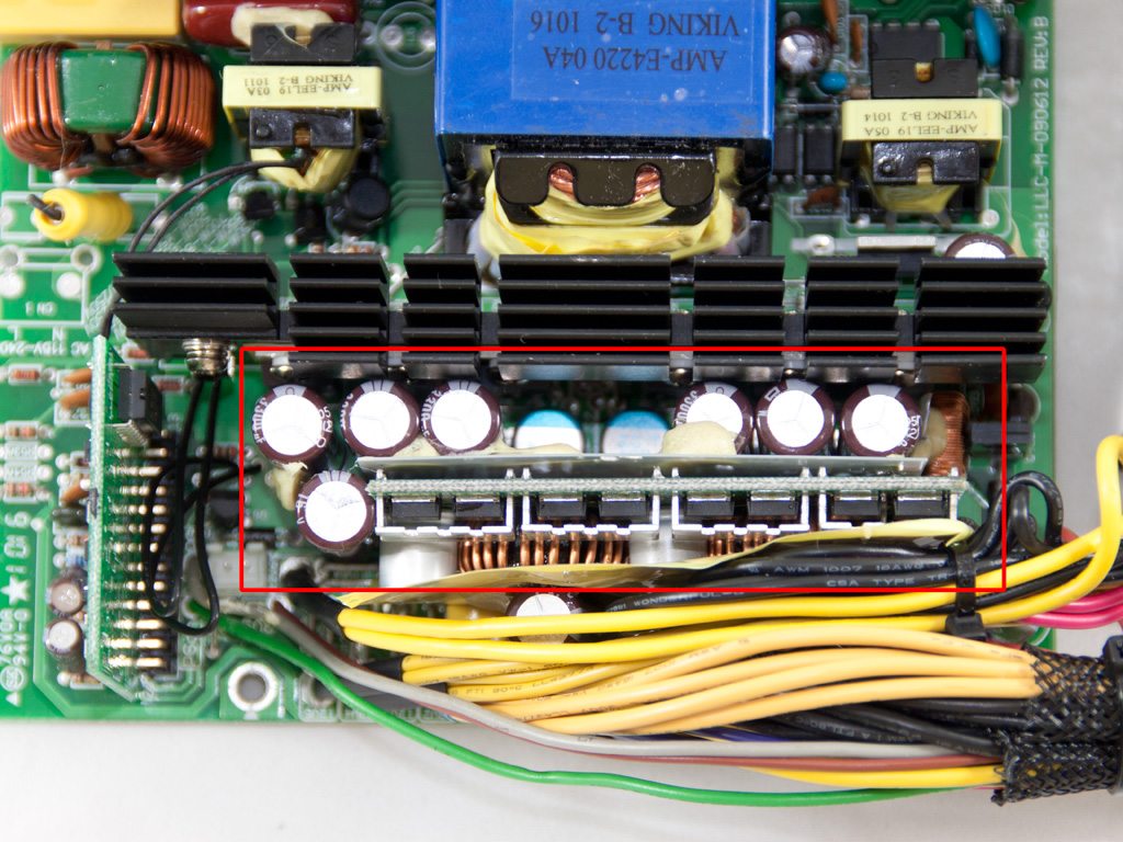
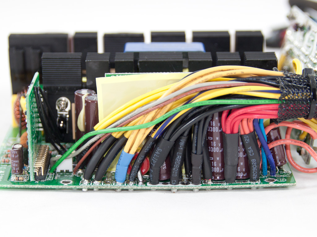
In the secondary side synchronous design is used for the generation of +12V, so six IPP040N06N3 are used. The minor rails are generated through +12V with the help of two DC-DC VRMs (Voltage regulation Modules). All capacitors, polymer and electrolytic ones, in the secondary are from Chemi-Con. Finally, on the secondary heatsink there is a thermistor attached, for the fan speed control.
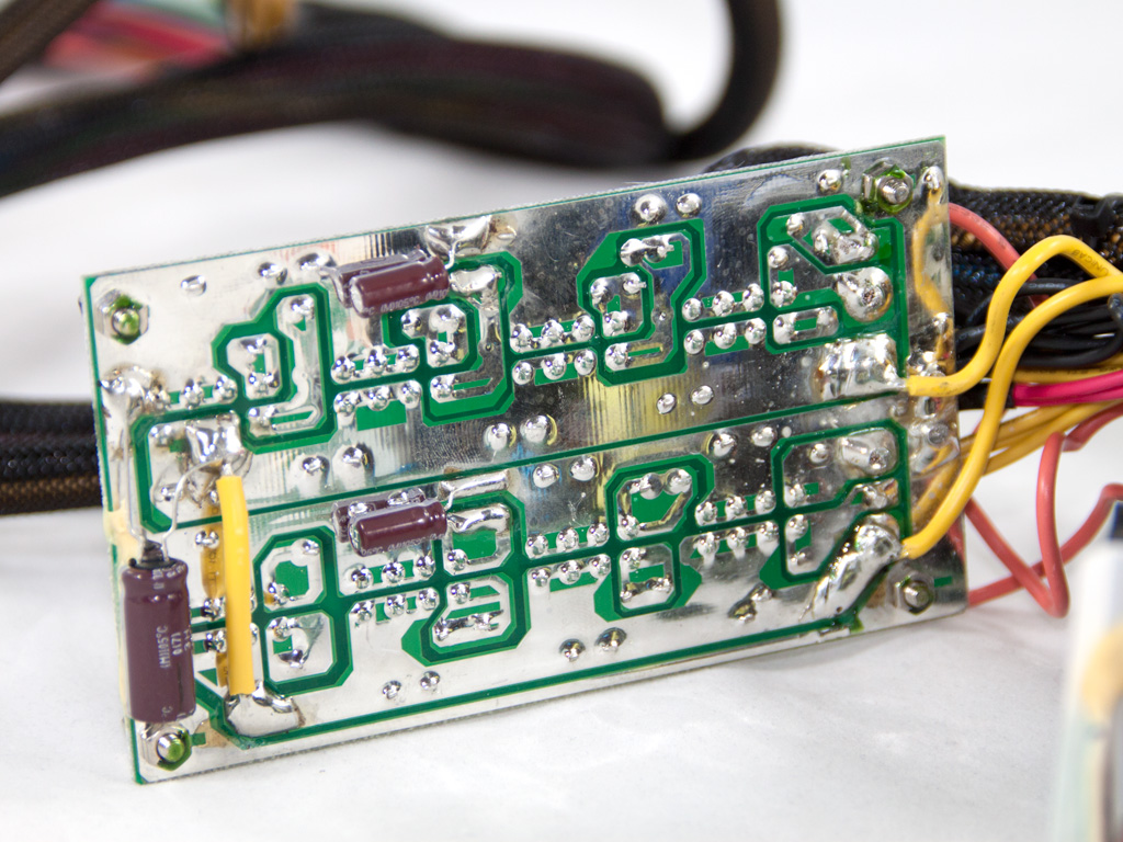

Behind the modular PCB there are three electrolytic caps, clearly hand-soldered afterwards, that provide some extra ripple filtering. Soldering quality and workmanship on the main PCB are good but not top notch.
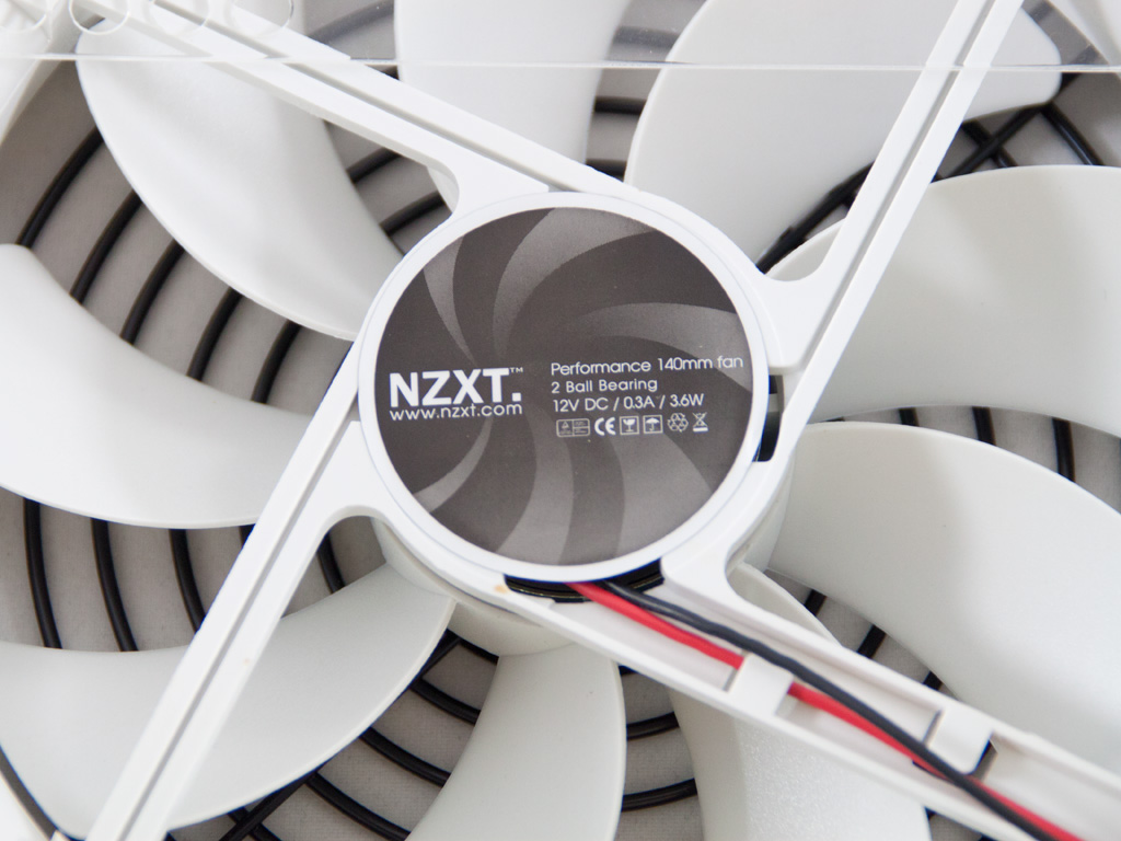
The cooling fan carries an NZXT label so we couldn't spot the real manufacturer.
Jun 30th, 2025 22:36 CDT
change timezone
Latest GPU Drivers
New Forum Posts
- GravityMark v1.89 GPU Benchmark (303)
- Post your Cinebench 2024 score (658)
- GPU PerfCap Reason PWR (8)
- Laptop overclocking adventures (1238)
- [INTEL]-How To Update Your Microcode for Intel HX 13/14th Gen. CPUs Laptops/Mobile Easily. (172)
- Will you buy a RTX 5090? (584)
- The TPU UK Clubhouse (26530)
- Optane and "enable write caching " (27)
- Question about Intel Optane SSDs (87)
- Do you use Linux? (664)
Popular Reviews
- ASUS ROG Crosshair X870E Extreme Review
- Sapphire Radeon RX 9060 XT Pulse OC 16 GB Review - Samsung Memory Tested
- AVerMedia CamStream 4K Review
- Lexar NQ780 4 TB Review
- AMD Ryzen 7 9800X3D Review - The Best Gaming Processor
- Upcoming Hardware Launches 2025 (Updated May 2025)
- Sapphire Radeon RX 9070 XT Nitro+ Review - Beating NVIDIA
- AMD Ryzen 9 9950X3D Review - Great for Gaming and Productivity
- NVIDIA GeForce RTX 5060 8 GB Review
- ASRock Phantom Gaming Z890 Riptide Wi-Fi Review
TPU on YouTube
Controversial News Posts
- Intel's Core Ultra 7 265K and 265KF CPUs Dip Below $250 (288)
- NVIDIA Grabs Market Share, AMD Loses Ground, and Intel Disappears in Latest dGPU Update (204)
- Some Intel Nova Lake CPUs Rumored to Challenge AMD's 3D V-Cache in Desktop Gaming (140)
- NVIDIA Launches GeForce RTX 5050 for Desktops and Laptops, Starts at $249 (105)
- Microsoft Partners with AMD for Next-gen Xbox Hardware (105)
- Intel "Nova Lake‑S" Series: Seven SKUs, Up to 52 Cores and 150 W TDP (100)
- NVIDIA GeForce RTX 5080 SUPER Could Feature 24 GB Memory, Increased Power Limits (94)
- Reviewers Bemused by Restrictive Sampling of RX 9060 XT 8 GB Cards (88)