 19
19
Pichau Gaming Nidus 500 W Review
Protection Features Evaluation, DC Power Sequencing & EMC Pre-Compliance Testing »Advanced Transient Response Tests
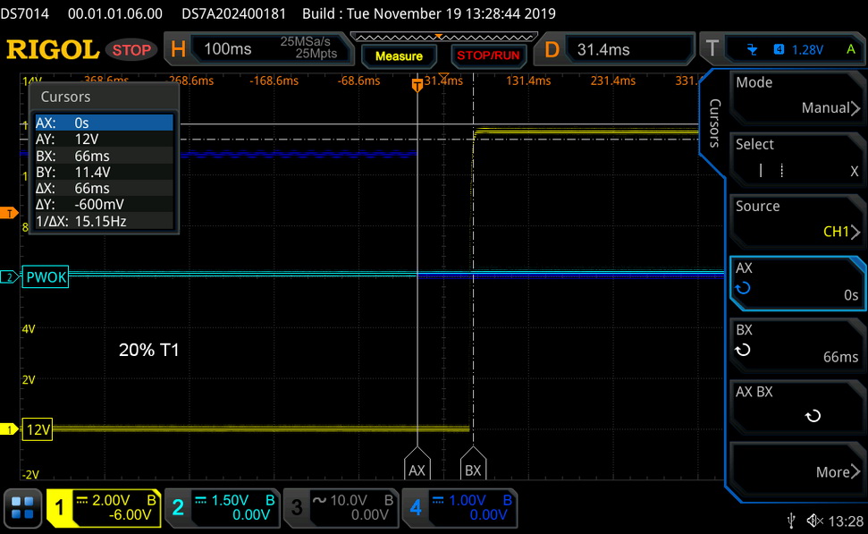
In these tests, we monitor the response of the PSU in two different scenarios. First, a transient load (10 A at +12V, 5 A at +5V, 5 A at +3.3V, and 0.5 A at 5VSB) is applied to the PSU for 200 ms while the latter is working at 20% load. In the second scenario, the PSU, while working at 50% load, is hit by the same transient load. We measure the voltage drops the transient load causes with our oscilloscope in both tests. Voltages should remain within the regulation limits defined by the ATX specification.Real-world usage always has a PSU work with loads that change depending on whether the CPU or graphics cards are busy, which makes whether the PSU can keep its rails within the ranges defined by the ATX specification important. The smaller the deviations, the steadier the system will be, which results in less stress being applied to its components.
We should note that the ATX specification requires for capacitive loading during the transient tests, but in our methodology, we chose to apply the worst-case scenario with no extra capacitance on the rails. Although the ATX specifications asks for this capacitance, your system—the mainboard and its other parts—may not provide it, which we have to keep in mind as well.
| Advanced Transient Response 20% - 5 Hz | ||||
|---|---|---|---|---|
| Voltage | Before | After | Change | Pass/Fail |
| 12 V | 11.971V | 11.625V | 2.89% | Pass |
| 5 V | 5.076V | 4.890V | 3.66% | Pass |
| 3.3 V | 3.385V | 3.163V | 6.56% | Pass |
| 5VSB | 5.051V | 4.986V | 1.29% | Pass |
| Advanced Transient Response 50% - 5 Hz | ||||
|---|---|---|---|---|
| Voltage | Before | After | Change | Pass/Fail |
| 12 V | 11.914V | 11.531V | 3.21% | Pass |
| 5 V | 5.055V | 4.859V | 3.88% | Pass |
| 3.3 V | 3.361V | 3.130V | 6.87% | Fail |
| 5VSB | 5.017V | 4.943V | 1.47% | Pass |
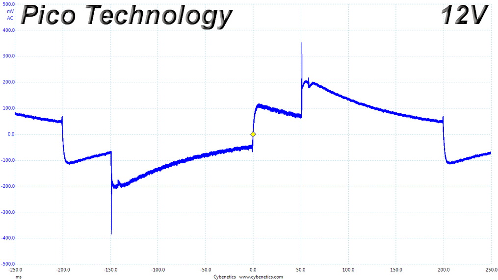
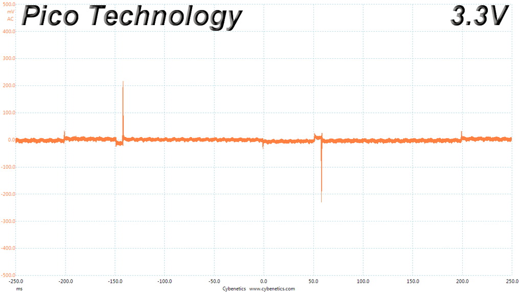
Because of the old platform, the transient response is not that good, especially at +12 V and 3.3 V. The 3.3 V rail fails to keep its voltage in control during the second test, dropping below 3.14 V, which is the lowest limit the ATX specification allows.
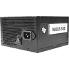
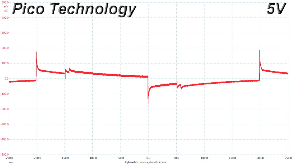
Below are the oscilloscope screenshots we took during Advanced Transient Response testing.
Transient Response at 20% Load
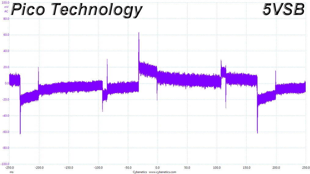
Transient Response at 50% Load
Turn-On Transient Tests
We measure the response of the PSU in more straightforward scenarios of transient load, during the power-on phase of the PSU, in the next set of tests. In the first test, we turn the PSU off, dial the maximum current the 5VSB can output, and then switch on the PSU. In the second test, we dial the maximum load +12V can handle and start the PSU while the PSU is in standby mode. In the last test, while the PSU is completely switched off (we cut off power or switch the PSU off by flipping its on/off switch), we dial the maximum load the +12V rail can handle before switching the PSU on from the loader and restoring power. The ATX specification states that recorded spikes on all rails should not exceed 10% of their nominal values (e.g., +10% for +12V is 13.2 V and 5.5 V for +5V).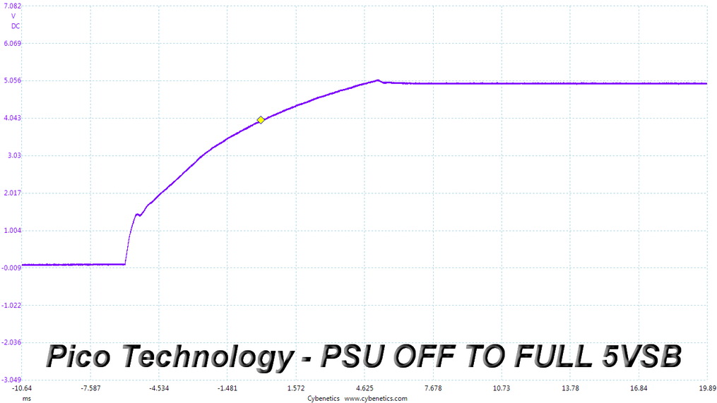
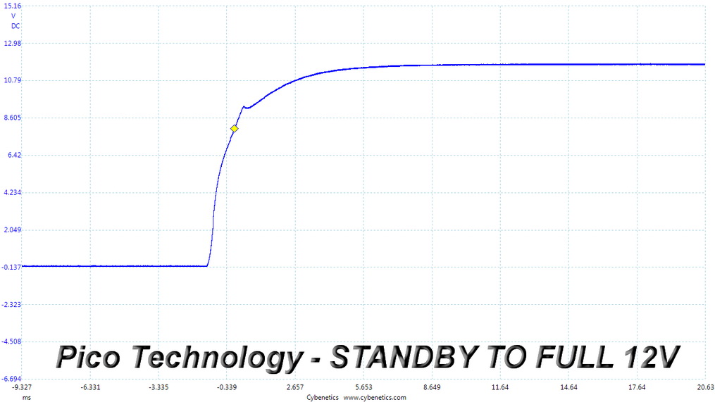
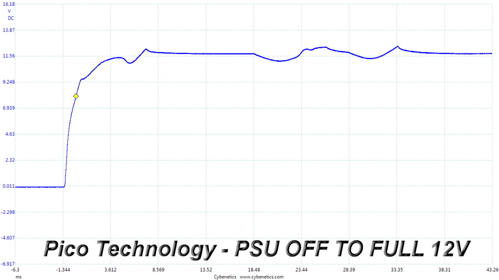
The results in the first two tests are fine. In the last test, though, it takes quite some time for the rail to settle down to its nominal voltage.
Power Supply Timing Tests
| Power Supply Timing | ||||
|---|---|---|---|---|
| Parameter | Description | Value | ||
| Required | Recommended for NON-Alternative Sleep Mode1 | Recommended for Alternative Sleep Mode | ||
| T0 | AC power on time | < 2s | - | - |
| T1 | Power-on time | < 500 ms | < 200 ms | < 150 ms |
| T2 | Rise time | 0.2 - 20 ms | - | - |
| T3 | PWR_OK delay | 100 - 500 ms | 100 - 250 ms | 100 - 150 ms |
| T4 | PWR_OK rise time | < 10 ms | - | - |
| T5 | AC loss to PWR_OK hold-up time | > 16 ms | - | - |
| T6 | PWR_OK inactive to DC loss delay | > 1 ms | - | - |
The table above lists all required and recommended power supply timing values. The values in the column "Recommended for Non-Alternative Sleep Mode" will be required starting in 2020.
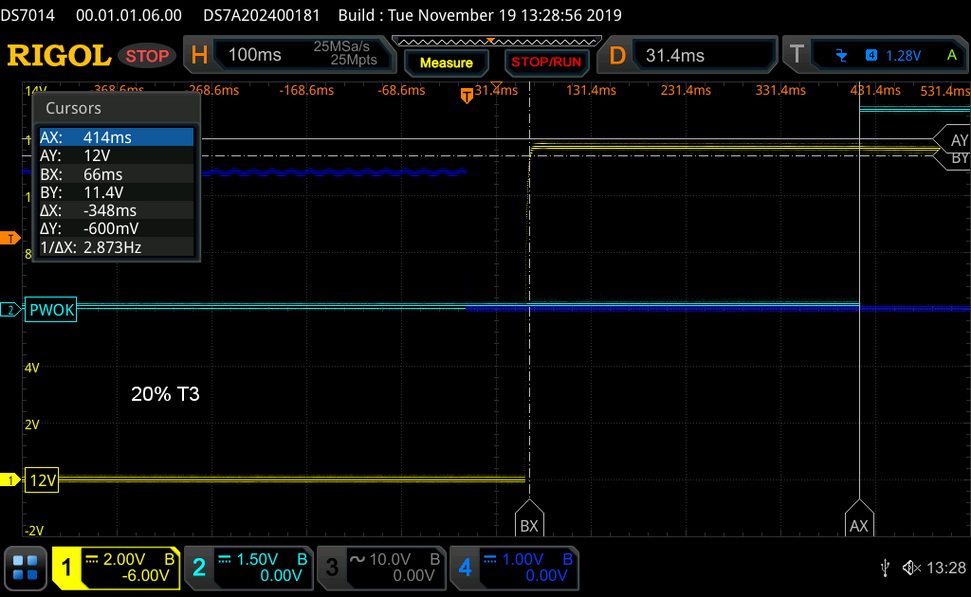
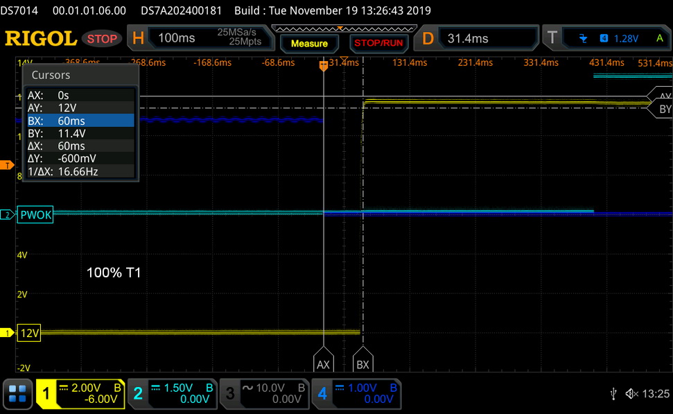

| T1 (Power-on time) & T3 (PWR_OK delay) | ||
|---|---|---|
| Load | T1 | T3 |
| 20% | 66 ms | 348 ms |
| 100% | 60 ms | 351 ms |
This unit is not compatible with alternative sleep mode because the PWR_OK delay time exceeds 150 ms.
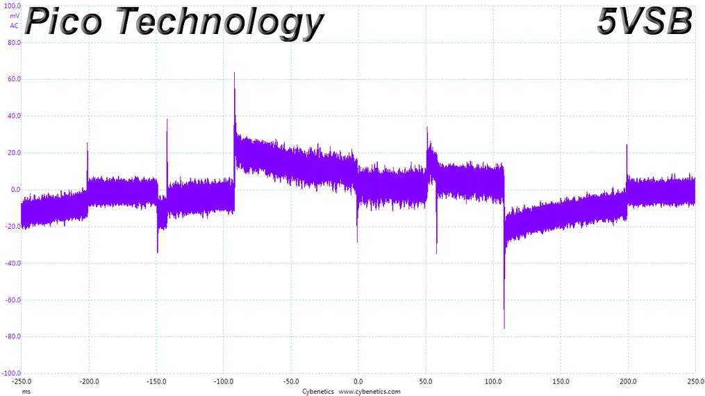
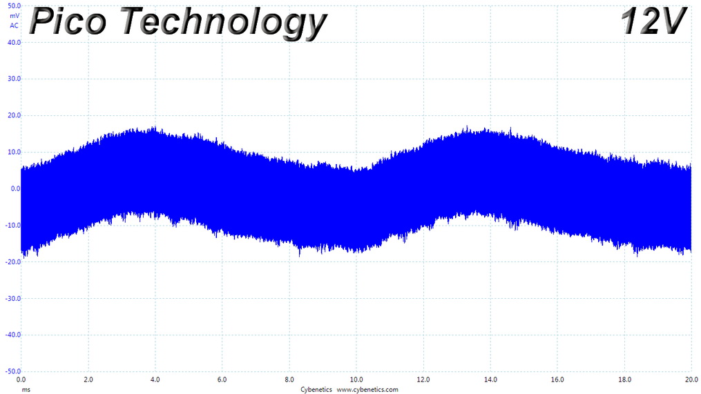
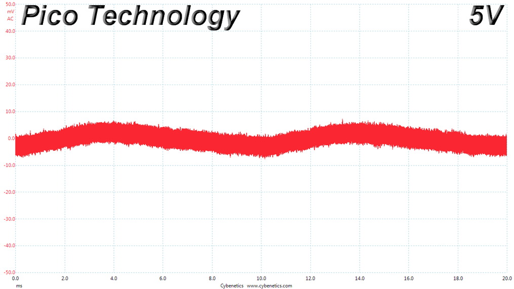
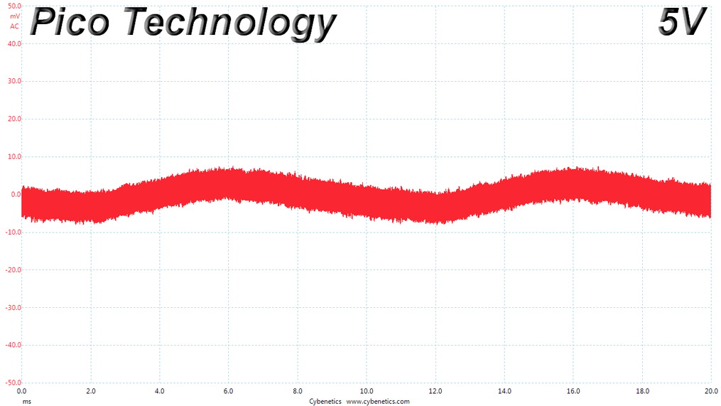
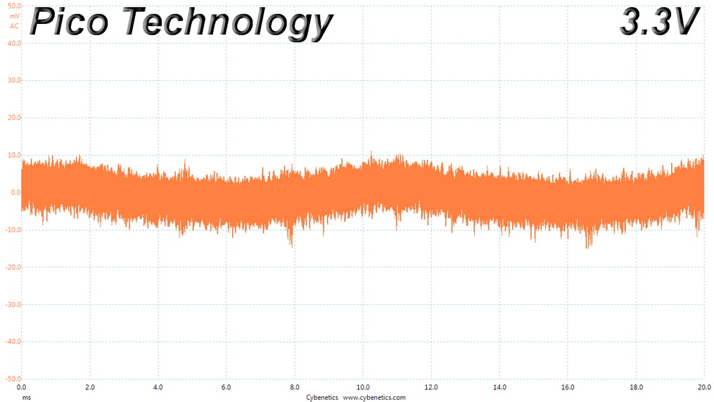
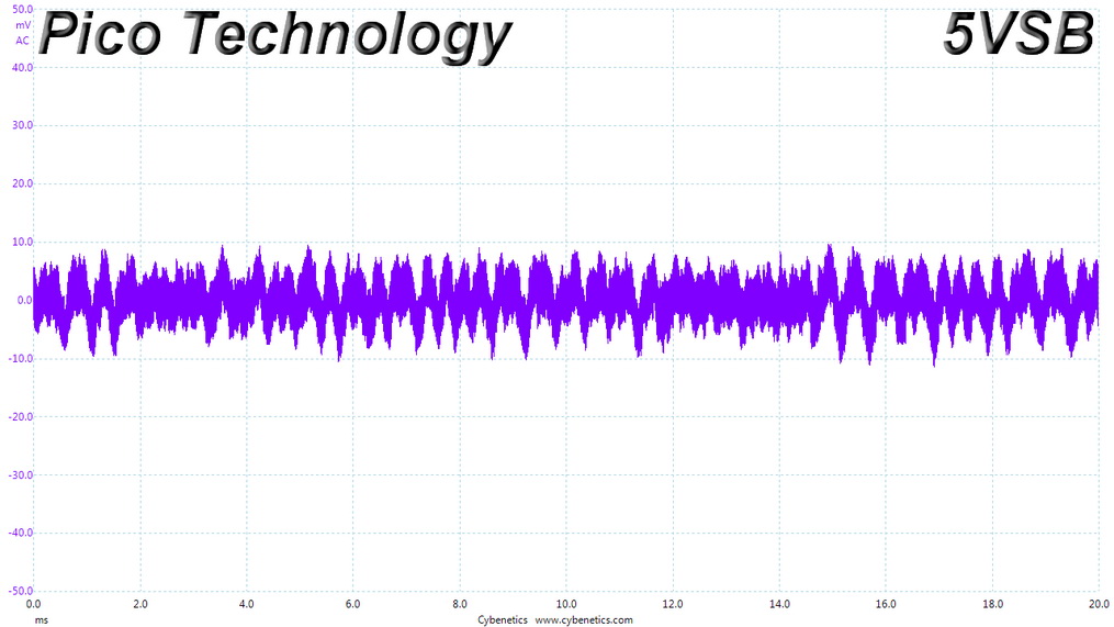
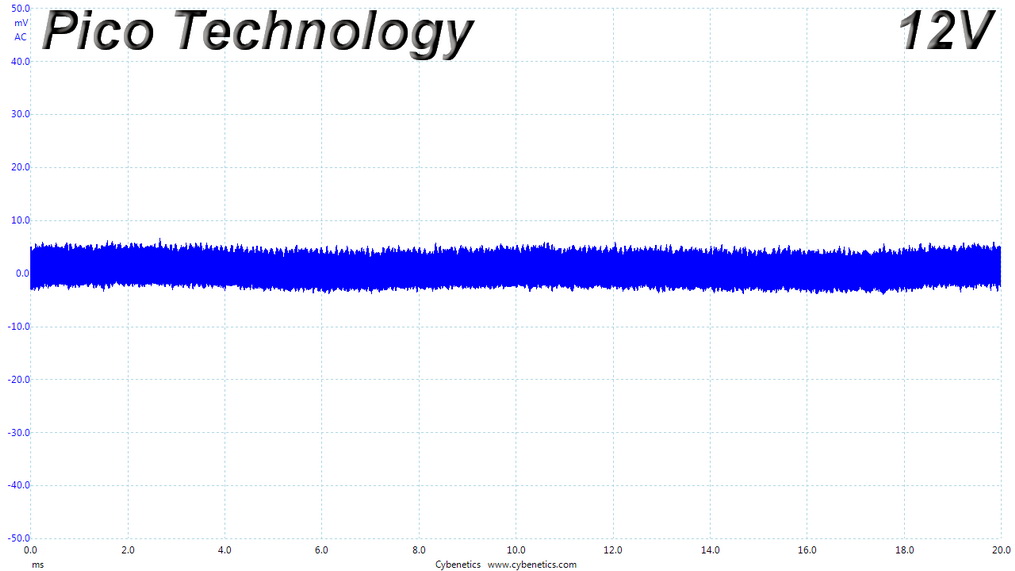
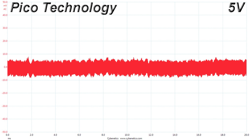
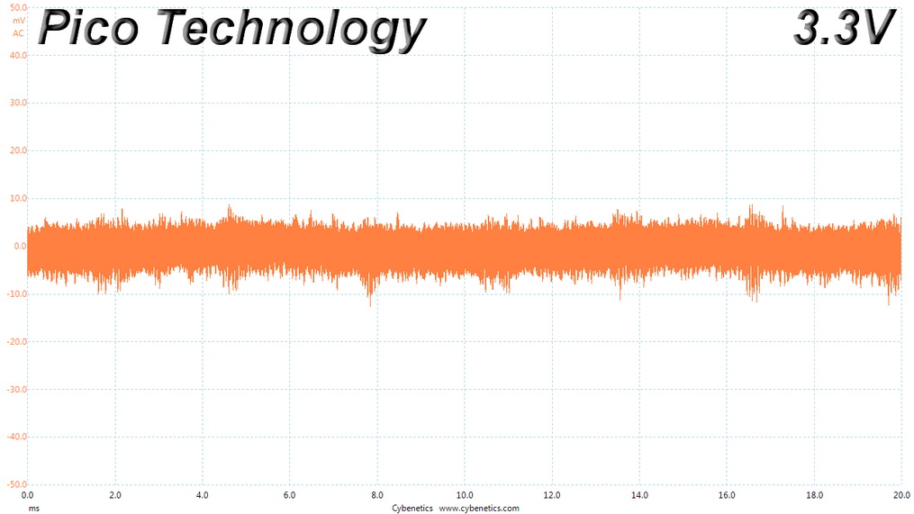
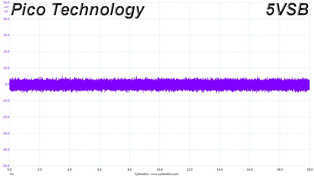
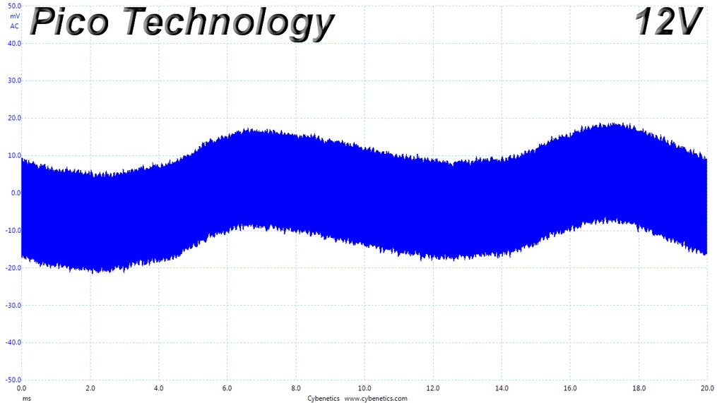
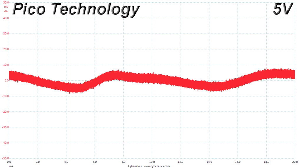
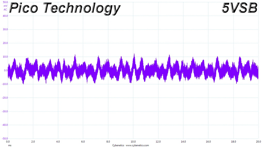
Ripple Measurements
Ripple represents the AC fluctuations (periodic) and noise (random) found in the DC rails of PSUs. Ripple significantly decreases the life span of capacitors because it increases their temperature; a 10 °C increase can cut into a capacitor's life span by up to 50 percent. Ripple also plays an important role in overall system stability, especially when it is overclocked. The ripple limits according to the ATX specification are 120 mV (+12V) and 50 mV (+5V, +3.3V, and 5VSB).| Ripple Measurements - Pichau Gaming Nidus 500 | |||||
|---|---|---|---|---|---|
| Test | 12 V | 5 V | 3.3 V | 5VSB | Pass/Fail |
| 10% Load | 7.4 mV | 9.6 mV | 14.5 mV | 14.0 mV | Pass |
| 20% Load | 8.2 mV | 9.6 mV | 15.4 mV | 17.6 mV | Pass |
| 30% Load | 9.0 mV | 10.0 mV | 15.8 mV | 14.1 mV | Pass |
| 40% Load | 40.2 mV | 10.1 mV | 15.3 mV | 15.5 mV | Pass |
| 50% Load | 10.9 mV | 10.4 mV | 15.4 mV | 20.8 mV | Pass |
| 60% Load | 12.8 mV | 9.8 mV | 16.6 mV | 16.8 mV | Pass |
| 70% Load | 14.2 mV | 9.9 mV | 17.7 mV | 18.0 mV | Pass |
| 80% Load | 19.0 mV | 10.2 mV | 20.1 mV | 24.8 mV | Pass |
| 90% Load | 25.4 mV | 10.9 mV | 20.4 mV | 25.1 mV | Pass |
| 100% Load | 39.5 mV | 15.2 mV | 26.9 mV | 25.8 mV | Pass |
| 110% Load | 48.0 mV | 17.3 mV | 29.1 mV | 25.7 mV | Pass |
| Crossload 1 | 14.6 mV | 20.8 mV | 24.3 mV | 13.2 mV | Pass |
| Crossload 2 | 44.6 mV | 18.5 mV | 23.4 mV | 23.0 mV | Pass |
Ripple suppression is satisfactory for a PSU of this price range, also as it of course does not use any extra capacitors on the cables.
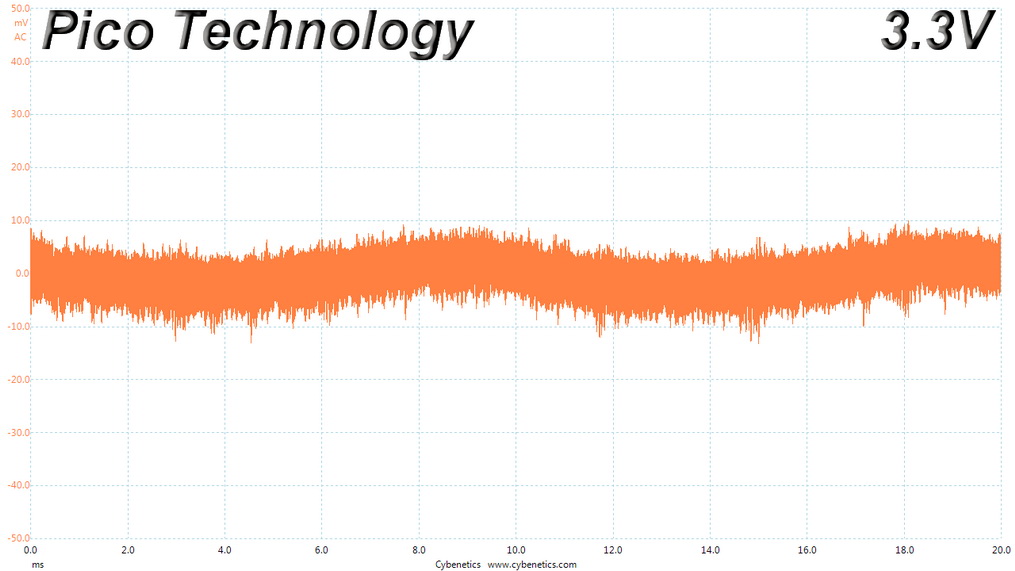
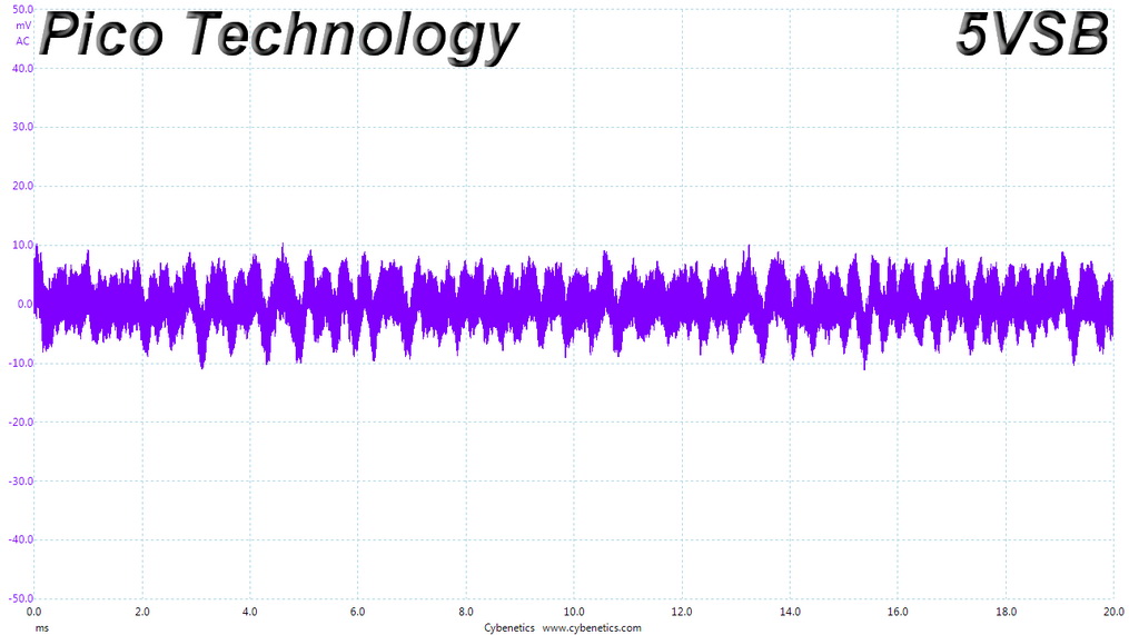
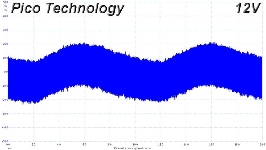
Ripple at Full Load
Ripple at 110% Load
Ripple at Crossload 1
Ripple at Crossload 2

Jul 1st, 2025 23:04 CDT
change timezone
Latest GPU Drivers
New Forum Posts
- Last game you purchased? (858)
- What would you buy? (33)
- PCMA2305 Phase Change Metal Alloy (PCMA) (7)
- Best motherboards for XP gaming (18)
- Need help with X-Fi xtremegamer Fatal1ty card (0)
- Is my m2 possibly fake ? and possible laptop hardware damage ? (28)
- HP Zbook 15 G2 GPU Upgrade (4)
- Help me overclocking my GSkill Ripjaws 3200MHz CL 16 DDR4 RAMs. (20)
- MACPRO 3,1 booting windows (0)
- My PCIe5 SSD is slow. Samsung 9100 PRO (29)
Popular Reviews
- ASUS ROG Crosshair X870E Extreme Review
- Crucial T710 2 TB Review - Record-Breaking Gen 5
- Sapphire Radeon RX 9060 XT Pulse OC 16 GB Review - An Excellent Choice
- AVerMedia CamStream 4K Review
- Upcoming Hardware Launches 2025 (Updated May 2025)
- AMD Ryzen 7 9800X3D Review - The Best Gaming Processor
- Lexar NQ780 4 TB Review
- Sapphire Radeon RX 9070 XT Nitro+ Review - Beating NVIDIA
- AMD Ryzen 9 9950X3D Review - Great for Gaming and Productivity
- NVIDIA GeForce RTX 5060 8 GB Review
TPU on YouTube
Controversial News Posts
- Intel's Core Ultra 7 265K and 265KF CPUs Dip Below $250 (288)
- NVIDIA Grabs Market Share, AMD Loses Ground, and Intel Disappears in Latest dGPU Update (208)
- Some Intel Nova Lake CPUs Rumored to Challenge AMD's 3D V-Cache in Desktop Gaming (140)
- NVIDIA GeForce RTX 5080 SUPER Could Feature 24 GB Memory, Increased Power Limits (112)
- Microsoft Partners with AMD for Next-gen Xbox Hardware (105)
- NVIDIA Launches GeForce RTX 5050 for Desktops and Laptops, Starts at $249 (105)
- Intel "Nova Lake‑S" Series: Seven SKUs, Up to 52 Cores and 150 W TDP (100)
- NVIDIA DLSS Transformer Cuts VRAM Usage by 20% (91)