 8
8
Rosewill Tachyon 1000 W Review
Voltage Regulation, Hold-up Time & Inrush Current »A Look Inside & Component Analysis
Before reading this page, we strongly suggest a look at this article, which will help you understand the internal components of a PSU better.


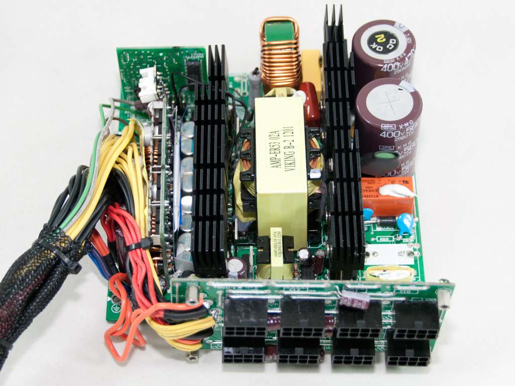
As we already mentioned, all Tachyons are built by Super Flower. The platform they use is their high-end one – the same one that the Golden King models exploit. The design is modern, and the primary side has a half-bridge topology along with an LLC converter for a significant efficiency boost. The secondary side uses Synchronous design with two DC-DC converters for the generation of the minor rails. Also, the PSUs internals only use Japanese polymer and electrolytic caps provided by Nippon Chemi-Con, which is a clear indication of the PSU's high-end orientation.
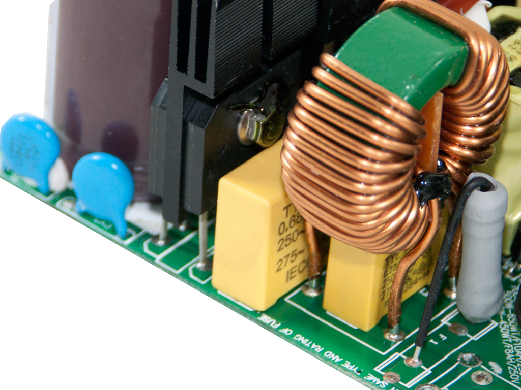
Behind the AC receptacle is a small PCB holding some of the transient filtering components, namely two Y caps, one X cap, and a CM choke. The second stage of the transient filter on the main PCB includes another CM choke with two pairs of X and Y caps. Unfortunately, Super Flower refuses to introduce an MOV into any of their implementations, something we don't approve of.

The two parallel bridge rectifiers are bolted onto the APFC/primary heatsink. Their model number is US30KB80R, and each one can handle up to 30 A, so they are too strong, even for a 1 kW capacity PSU.


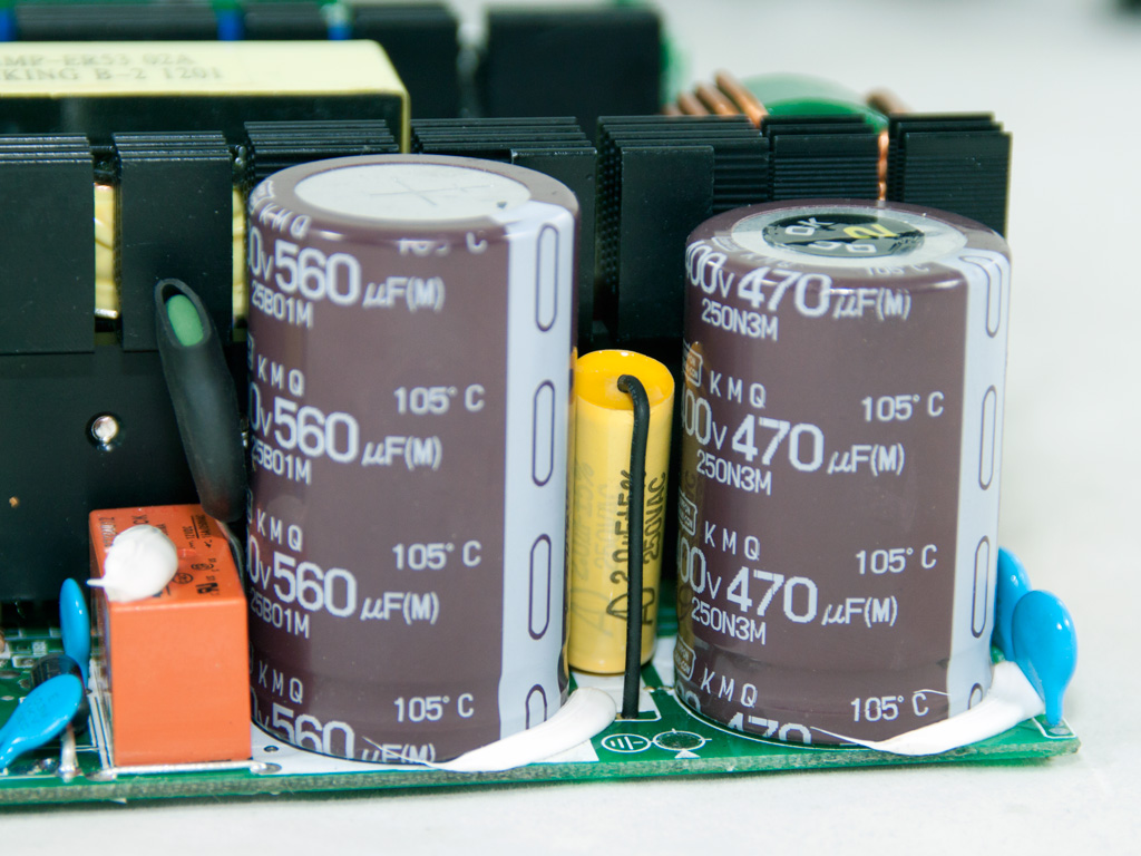
In the APFC, two IPW50R140CP mosfets separate the pulsating DC signal, and we also find two boost diodes, instead of the usual one, offering up their services. The hold-up caps are provided by Nippon Chemi-Con, but they don't share the same capacity. The larger one has 560 μF capacity and the smaller has 470 μF capacity. Both are rated at 105°C, 400 V and both belong to Nippon's KMQ series.


We removed the huge APFC choke to provide you a clear view to the NTC thermistor, which offers protection against large inrush currents, and the orange relay that cut's it off the circuit once the start-up phase finishes.
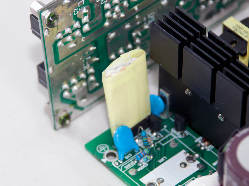

This small vertical daughter-board covered by EMI shielding-tape houses an NCP1653A PFC controller.

The two main switchers (Infineon IPW50R140CP) are configured in a half-bridge topology and do, along with an LLC resonant converter, provide high efficiency.

Τhe standby PWM controller is an ICE3B0565 IC.


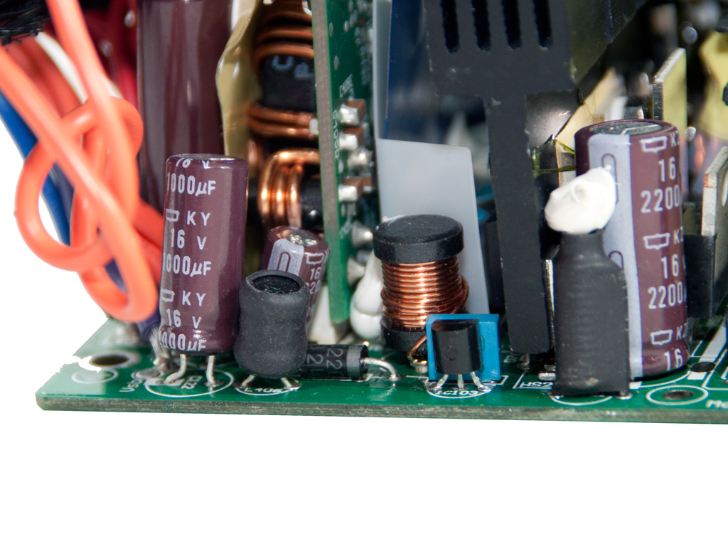
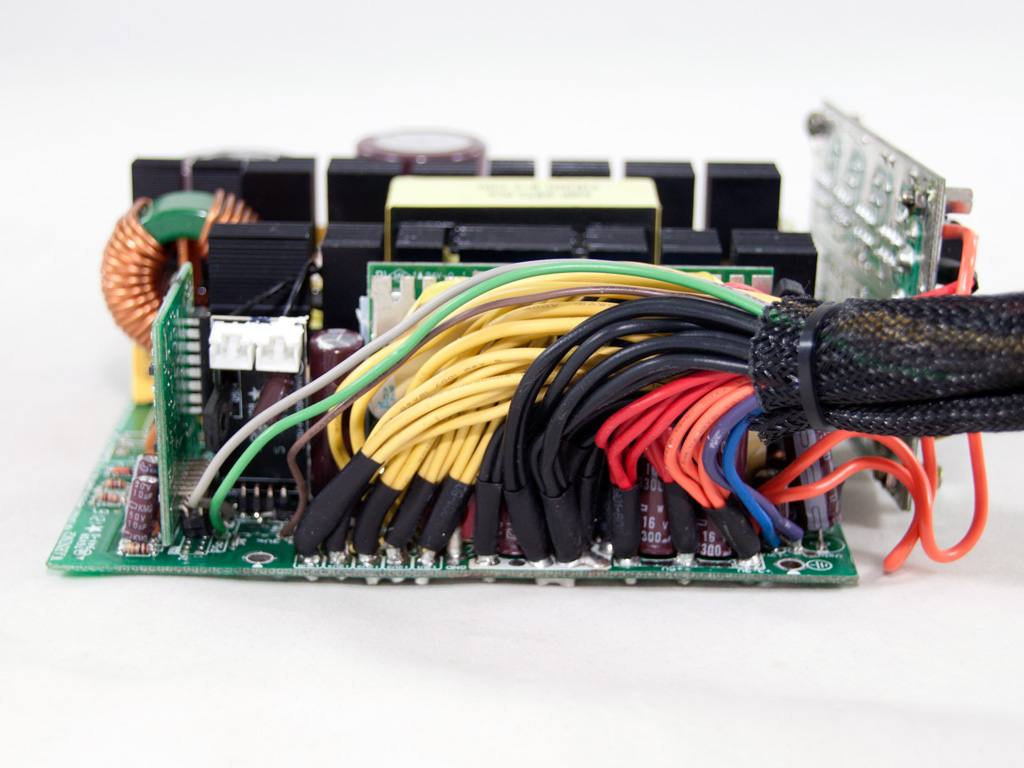
On the secondary side, a great number (ten!) of IPP041N04N fets rectify +12V. Each one can provide up to 80A in continuous mode, making ten far too much for the 996W that the +12V can, according to the specs, deliver. Also, enough polymer Nippon and some electrolytic caps (105°C; KZH; KZE and KY series) filter this rail.

Τhe minor rails are generated by two DC-DC converters housed on the same PCB. Four mosfets are used on each converter, and a metal shield protects them from interference.


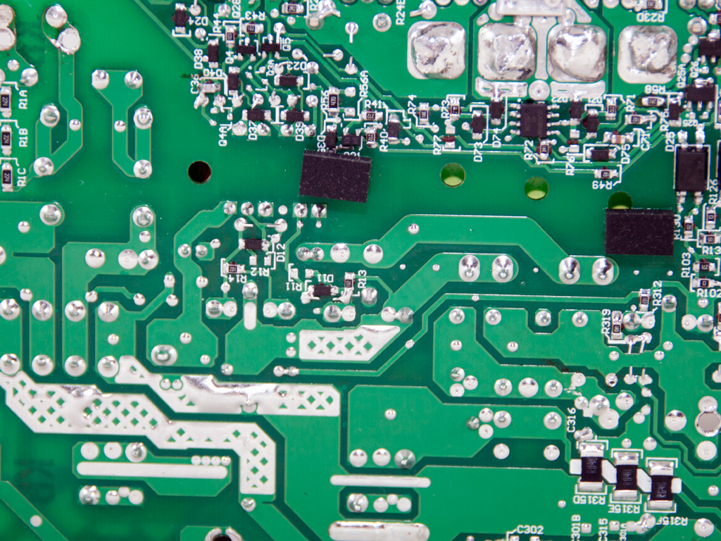
The LLC resonant controller is a proprietary IC with model number SF29601. It sits on a vertical daughter-board located on the secondary side. It handles the primary choppers and all the protection features of the unit. Since this is a custom made IC, there is no info about this on the net. On the solder side of this small PCB is an LM324ADG Quad Operational Amplifier. We should note that we used a photo taken from the internals of the Super Flower Golden King 1000 W, which uses exactly the same platform, since we couldn't get a clear photo of the SF29601 on the Tachyon.


Eight Nippon KY series caps on the front of the modular PCB provide extra ripple filtering to the DC outputs.
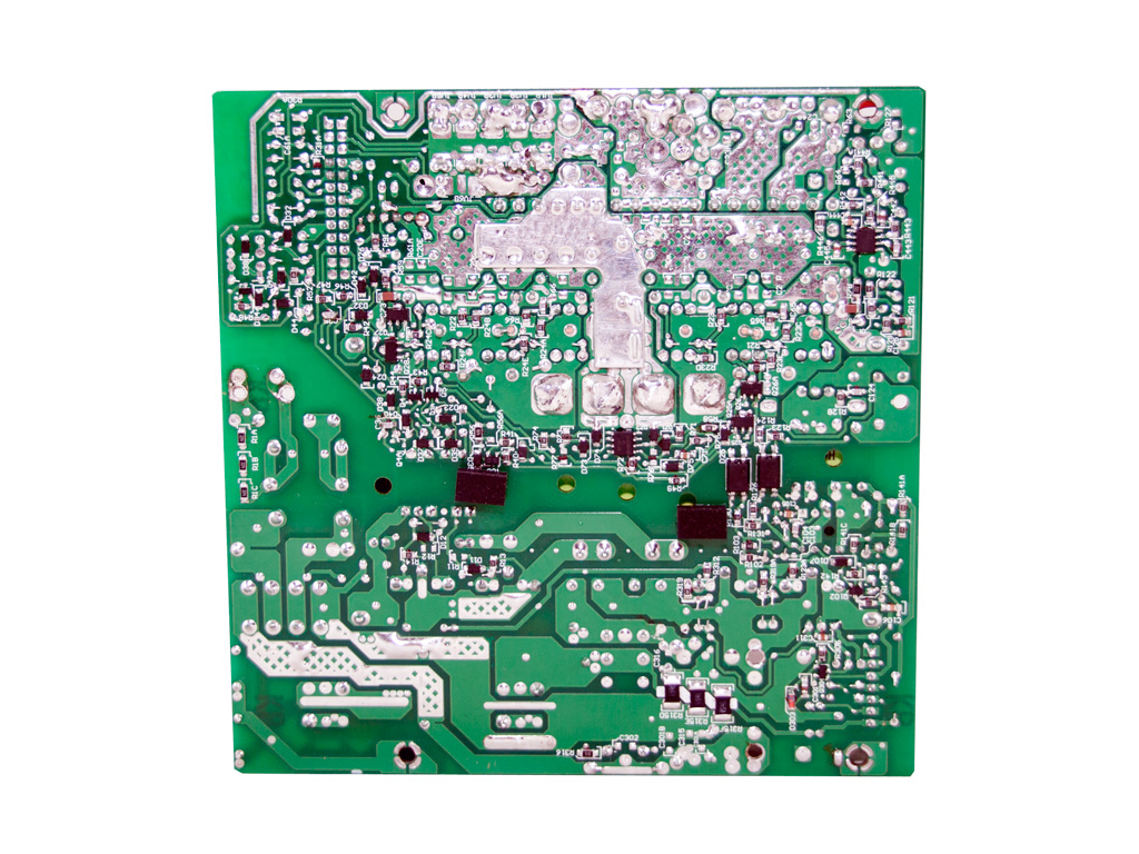

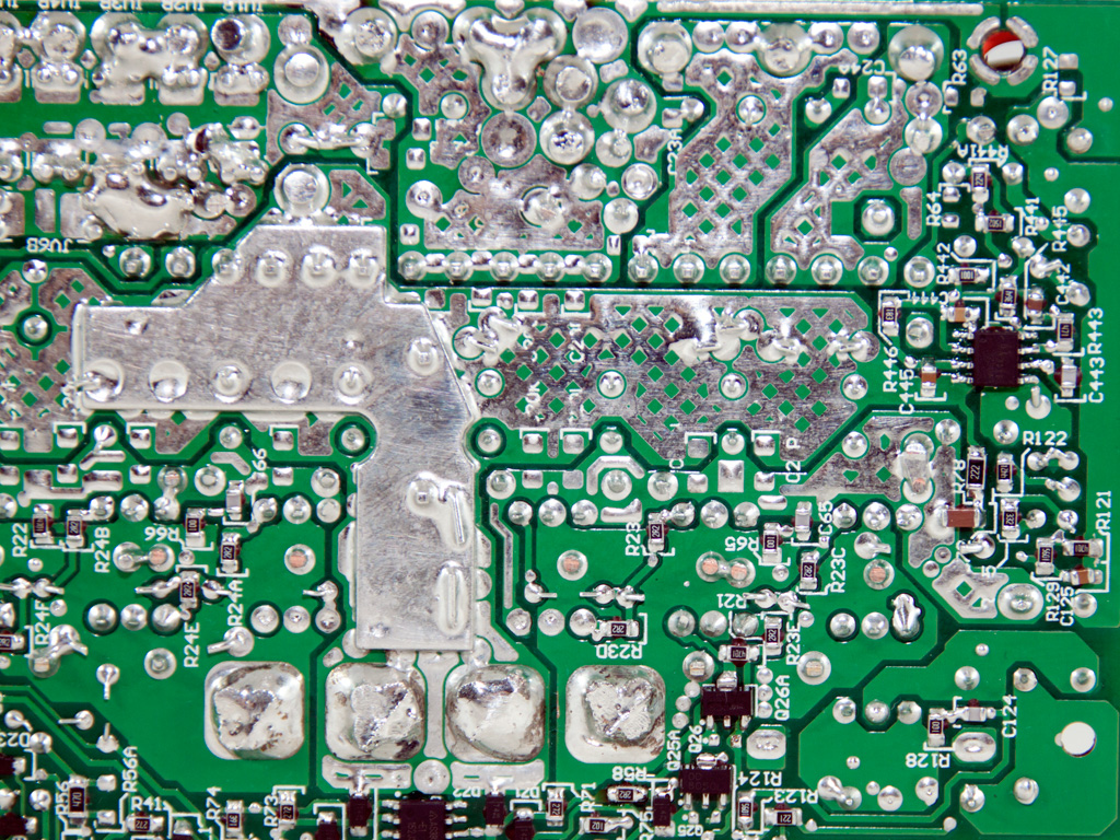

Soldering quality on the main PCB is really good, although it still doesn't reach Delta's and Seasonic's high-end implementations. Nevertheless, it does its job pretty well, as you will find out from the test results.


The fan carries Rosewill's logo but its model number (RL4Z S1402512HH) easily tells us that it is made by Globe Fan. It uses a sleeve bearing, which makes it quieter than a ball-bearings fan, but it doesn't last nearly as long. Its maximum speed is 1800 RPM when it delivers 135.74 CFM and outputs 36.7 dBA (according to the manufacturer). Finally, a small plastic baffle is attached onto the fan to direct the air towards the rear side of the unit.

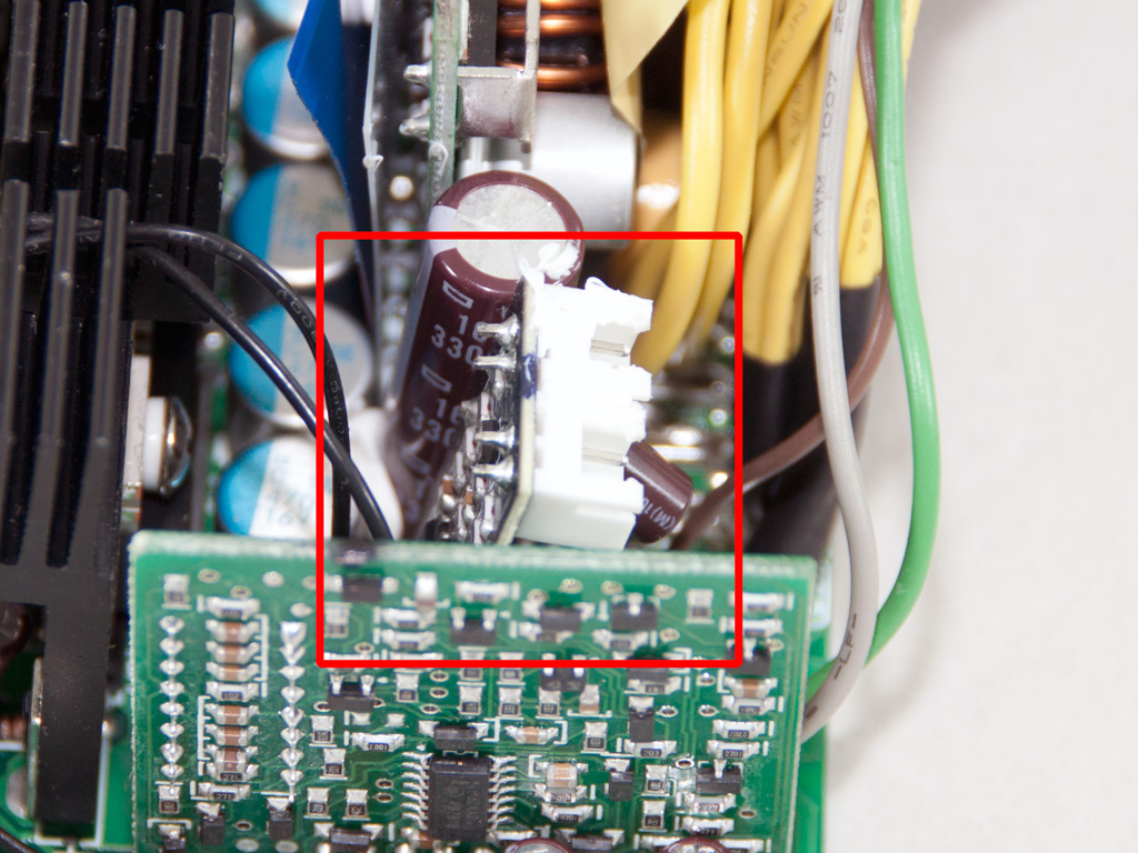
The fan control circuit is installed on a small vertical daughter-board in the secondary side. A quality problem we spotted is that this small PCB is only held in place by several weak solder joints on its base. These solder joints completely detached from the PCB once we tried to disconnect the fan header, although we applied minimal force and were extra cautious. This means that strong vibrations (during shipping for instance) may cause these joints to detach as well, which would break the fan circuit, so the fan won't spin at any load/internal temperature. Such a fan's malfunction will, to make things worse, easily pass unnoticed since the fan only spins up at higher loads and increased temperatures, and the PSU isn't equipped with OTP to shut down operation once internal temperature go through the roof. An easy fix to this problem would be to apply some glue around the PCB to secure it in place. Some build-quality points where obviously lost here.
Feb 24th, 2025 09:35 EST
change timezone
Latest GPU Drivers
New Forum Posts
- 9800 x3d overheating what is the stock voltage (6)
- Nvidia's GPU market share hits 90% in Q4 2024 (gets closer to full monopoly) (534)
- Help choose M.2 Key E Wifi card (12)
- Dirty Workaround for Crashing INTEL AX-210 WLAN with linux kernel (1)
- Microcenter GPU Stock status (12)
- atx 12v vs eps 12v (2)
- RTX 5090 ridiculous price! (179)
- can i connect a sata3 ssd 120GB to dell latitude c600 (18)
- Need help dumping/imaging Lenovo laptop BIOS (4)
- [Intel AX1xx/AX2xx/AX4xx/AX16xx/BE2xx/BE17xx] Intel Modded Wi-Fi Driver with Intel® Killer™ Features (278)
Popular Reviews
- ASUS GeForce RTX 5070 Ti TUF OC Review
- MSI GeForce RTX 5070 Ti Ventus 3X OC Review
- darkFlash DY470 Review
- MSI GeForce RTX 5070 Ti Vanguard SOC Review
- MSI GeForce RTX 5070 Ti Gaming Trio OC+ Review
- Galax GeForce RTX 5070 Ti 1-Click OC White Review
- Palit GeForce RTX 5070 Ti GameRock OC Review
- Fantech Aria II Pro Review
- Gigabyte GeForce RTX 5090 Gaming OC Review
- AMD Ryzen 7 9800X3D Review - The Best Gaming Processor
Controversial News Posts
- NVIDIA GeForce RTX 5090 Spotted with Missing ROPs, NVIDIA Confirms the Issue, Multiple Vendors Affected, RTX 5070 Ti, Too (458)
- AMD Radeon 9070 XT Rumored to Outpace RTX 5070 Ti by Almost 15% (304)
- AMD Plans Aggressive Price Competition with Radeon RX 9000 Series (271)
- AMD Radeon RX 9070 and 9070 XT Listed On Amazon - One Buyer Snags a Unit (247)
- Edward Snowden Lashes Out at NVIDIA Over GeForce RTX 50 Pricing And Value (241)
- AMD Denies Radeon RX 9070 XT $899 USD Starting Price Point Rumors (239)
- NVIDIA Investigates GeForce RTX 50 Series "Blackwell" Black Screen and BSOD Issues (238)
- New Leak Reveals NVIDIA RTX 5080 Is Slower Than RTX 4090 (215)