 28
28
Seasonic Focus SPX Series 750 W SFX PSU Review
Protection Features, Power Sequencing & EMC »Advanced Transient Response Tests
In these tests, we monitor the response of the PSU in two different scenarios. First, a transient load (15 A at +12V, 6 A at +5V, 6 A at +3.3V, and 0.5 A at 5VSB) is applied to the PSU for 20 ms while it is working at 20% load. In the second scenario, the PSU, while working at 50% load, is hit by the same transient load. In both tests, our oscilloscope measures the voltage drops caused by the transient load. All voltages should remain within the regulation limits defined by the ATX specification.During real-world usage, a PSU always operates under changing loads depending on whether the CPU or graphics card is busy. It is of immense importance that the PSU can keep its rails within limits defined by the ATX specification. Smaller deviations reduce the stress applied to system components.
We should note that the ATX specification requires capacitive loading during the transient tests. Still, in our methodology, we chose to apply the worst-case scenario with no extra capacitance on the rails. Although the ATX specification asks for this capacitance, your system—the mainboard and its other parts—may not provide it, which we have to keep in mind as well.
| Advanced Transient Response 20% - 50 Hz | ||||
|---|---|---|---|---|
| Voltage | Before | After | Change | Pass/Fail |
| 12V | 12.177V | 11.910V | 2.19% | Pass |
| 5V | 5.014V | 4.911V | 2.06% | Pass |
| 3.3V | 3.334V | 3.219V | 3.44% | Pass |
| 5VSB | 5.073V | 5.030V | 0.84% | Pass |
| Advanced Transient Response 50% - 50 Hz | ||||
|---|---|---|---|---|
| Voltage | Before | After | Change | Pass/Fail |
| 12V | 12.172V | 12.030V | 1.17% | Pass |
| 5V | 5.008V | 4.904V | 2.08% | Pass |
| 3.3V | 3.327V | 3.204V | 3.70% | Pass |
| 5VSB | 5.041V | 4.995V | 0.92% | Pass |
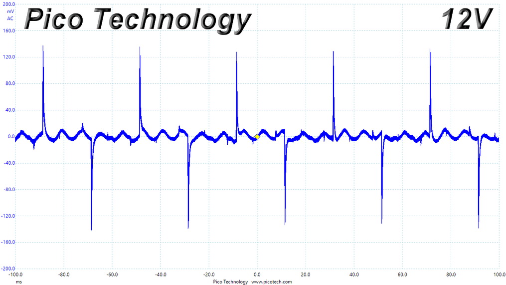
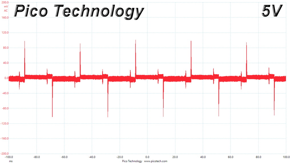
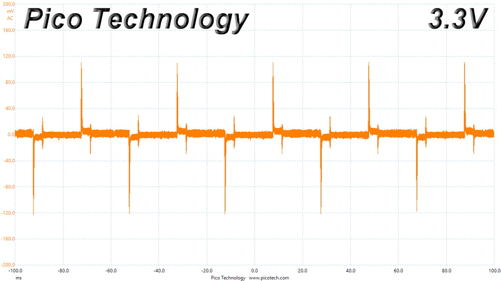
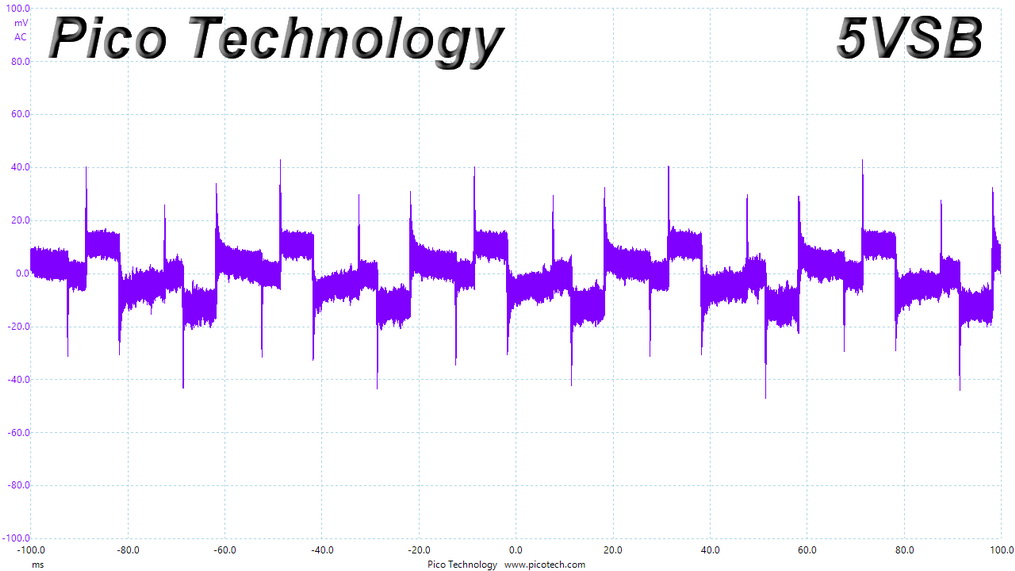
The transient response is good enough at +12 V and the minor rails and great at 5VSB, where it doesn't matter much.
Below are the oscilloscope screenshots we took during Advanced Transient Response testing.
Transient Response at 20% Load
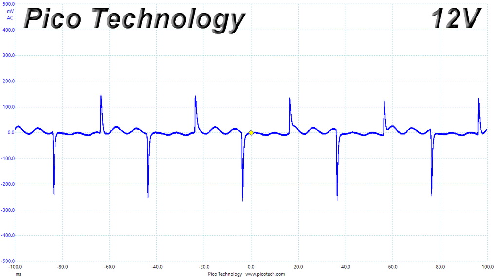
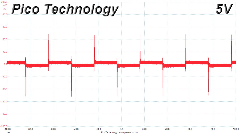
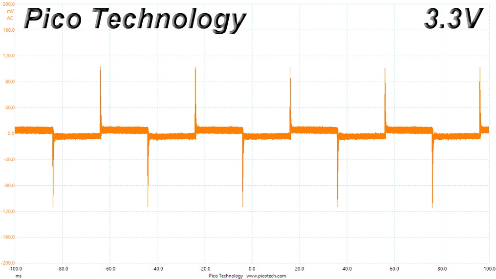
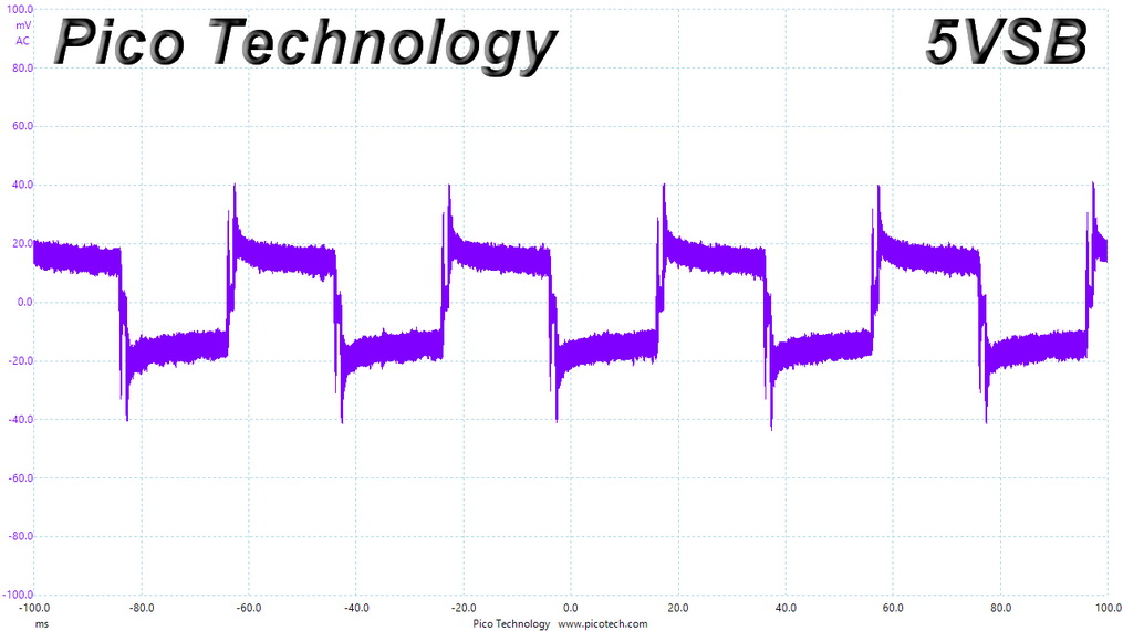
Transient Response at 50% Load
Turn-On Transient Tests
We measure the response of the PSU in more straightforward scenarios of transient load—during the power-on phase of the PSU—in the next set of tests. In the first test, we turn the PSU off, dial the maximum current the 5VSB can output, and then switch on the PSU. In the second test, we dial the maximum load +12V can handle and start the PSU while the PSU is in standby mode. In the last test, while the PSU is completely switched off (we cut off power or switch the PSU off by flipping its on/off switch), we dial the maximum load the +12V rail can handle before switching the PSU on from the loader and restoring power. The ATX specification states that recorded spikes on all rails should not exceed 10% of their nominal values (e.g., +10% for +12V is 13.2 V and 5.5 V for +5V).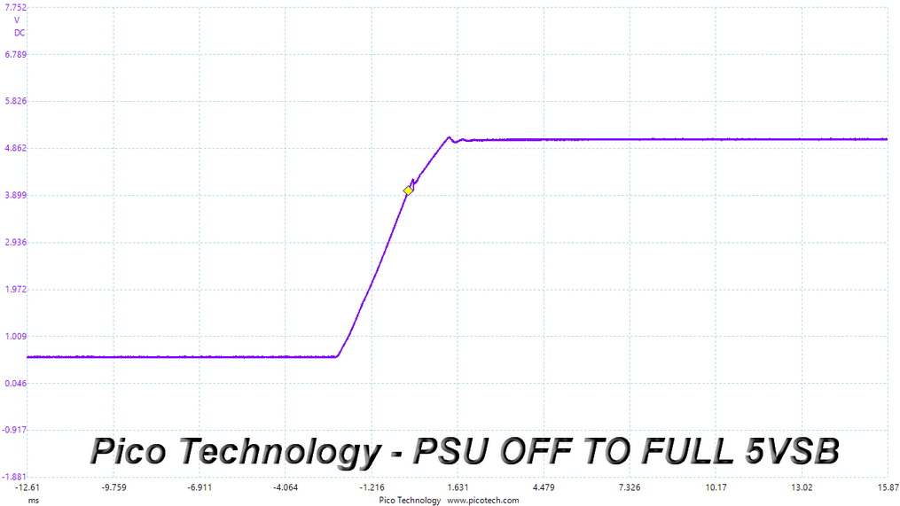
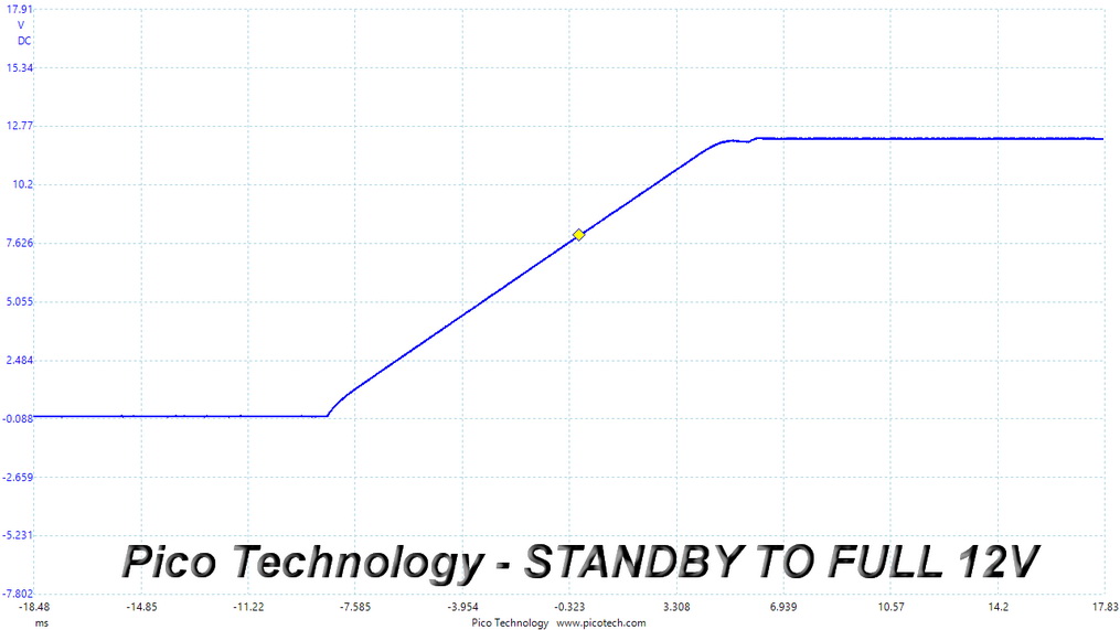
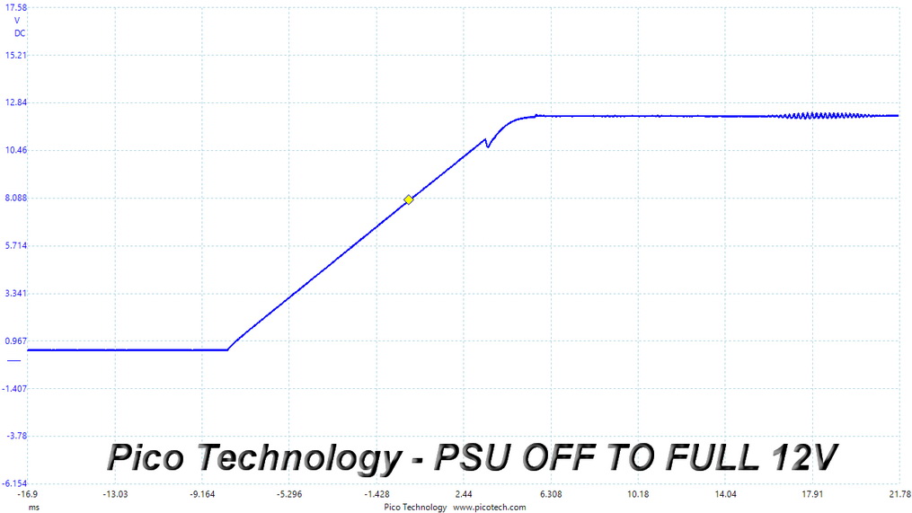
There is a small voltage overshoot at 5VSB, which won't cause any issues. I am a bit worried about the small drop at +12 V during the last test. The ATX specification requires the slope of the turn-on waveform to be positive and straight, without any drops.
Inrush Current
Inrush current, or switch-on surge, refers to the maximum, instantaneous input current drawn by an electrical device when it is first turned on. If high enough, inrush current can cause the tripping of circuit breakers and fuses and may also damage switches, relays, and bridge rectifiers. As a result, the lower the inrush current of a PSU right as it is turned on, the better.
Inrush current is low.
Leakage Current
We use a GW Instek GPT-9904 electrical safety tester to measure the leakage current. According to the IEC-60950-1 regulation, no power supply should exceed 3.5 mA of leakage current, which is low enough not to harm anyone touching the chassis. This test is performed at 110% of the rated input voltage.
Leakage current is higher than with similar offerings, but still well below the limit.
Jul 1st, 2025 23:05 CDT
change timezone
Latest GPU Drivers
New Forum Posts
- Last game you purchased? (858)
- What would you buy? (33)
- PCMA2305 Phase Change Metal Alloy (PCMA) (7)
- Best motherboards for XP gaming (18)
- Need help with X-Fi xtremegamer Fatal1ty card (0)
- Is my m2 possibly fake ? and possible laptop hardware damage ? (28)
- HP Zbook 15 G2 GPU Upgrade (4)
- Help me overclocking my GSkill Ripjaws 3200MHz CL 16 DDR4 RAMs. (20)
- MACPRO 3,1 booting windows (0)
- My PCIe5 SSD is slow. Samsung 9100 PRO (29)
Popular Reviews
- ASUS ROG Crosshair X870E Extreme Review
- Crucial T710 2 TB Review - Record-Breaking Gen 5
- Sapphire Radeon RX 9060 XT Pulse OC 16 GB Review - An Excellent Choice
- AVerMedia CamStream 4K Review
- Upcoming Hardware Launches 2025 (Updated May 2025)
- AMD Ryzen 7 9800X3D Review - The Best Gaming Processor
- Lexar NQ780 4 TB Review
- Sapphire Radeon RX 9070 XT Nitro+ Review - Beating NVIDIA
- AMD Ryzen 9 9950X3D Review - Great for Gaming and Productivity
- NVIDIA GeForce RTX 5060 8 GB Review
TPU on YouTube
Controversial News Posts
- Intel's Core Ultra 7 265K and 265KF CPUs Dip Below $250 (288)
- NVIDIA Grabs Market Share, AMD Loses Ground, and Intel Disappears in Latest dGPU Update (208)
- Some Intel Nova Lake CPUs Rumored to Challenge AMD's 3D V-Cache in Desktop Gaming (140)
- NVIDIA GeForce RTX 5080 SUPER Could Feature 24 GB Memory, Increased Power Limits (112)
- Microsoft Partners with AMD for Next-gen Xbox Hardware (105)
- NVIDIA Launches GeForce RTX 5050 for Desktops and Laptops, Starts at $249 (105)
- Intel "Nova Lake‑S" Series: Seven SKUs, Up to 52 Cores and 150 W TDP (100)
- NVIDIA DLSS Transformer Cuts VRAM Usage by 20% (91)