 19
19
Seasonic Platinum Series Fanless 520 W Review
Ripple Measurements »Advanced Transient Response Tests
In these tests, we monitor the response of the PSU in two different scenarios. First, a transient load (10 A at +12V, 5 A at 5V, 5 A at 3.3V, and 0.5 A at 5VSB) is applied to the PSU for 200 ms while the latter is working at a 20% load state. In the second scenario, the PSU, while working at 50% load, is hit by the same transient load. In both tests, we measure the voltage drops that the transient load causes using our oscilloscope. The voltages should remain within the regulation limits defined by the ATX specification. We must stress here that the above tests are crucial since they simulate transient loads that a PSU is very likely to handle (e.g., booting a RAID array, an instant 100% load of CPU/VGAs, etc.) We call these tests "Advanced Transient Response Tests", and they are designed to be very tough to master, especially for PSUs with capacities lower than 500 W.| Advanced Transient Response 20% | ||||
|---|---|---|---|---|
| Voltage | Before | After | Change | Pass/Fail |
| 12 V | 12.072V | 11.956V | 0.96% | Pass |
| 5 V | 5.053V | 4.992V | 1.21% | Pass |
| 3.3 V | 3.348V | 3.254V | 2.81% | Pass |
| 5VSB | 5.089V | 5.052V | 0.73% | Pass |
| Advanced Transient Response 50% | ||||
|---|---|---|---|---|
| Voltage | Before | After | Change | Pass/Fail |
| 12 V | 12.049V | 11.908V | 1.17% | Pass |
| 5 V | 5.048V | 4.969V | 1.56% | Pass |
| 3.3 V | 3.344V | 3.221V | 3.68% | Pass |
| 5VSB | 5.057V | 5.017V | 0.79% | Pass |
Deviations are low on all rails, so the registered voltage drops are small; that is, except for the 3.3V rail. The 3.3V rail registered deviations close to 4%, but the tight voltage regulation allowed the 3.3V rail to keep its voltage above 3.2V.
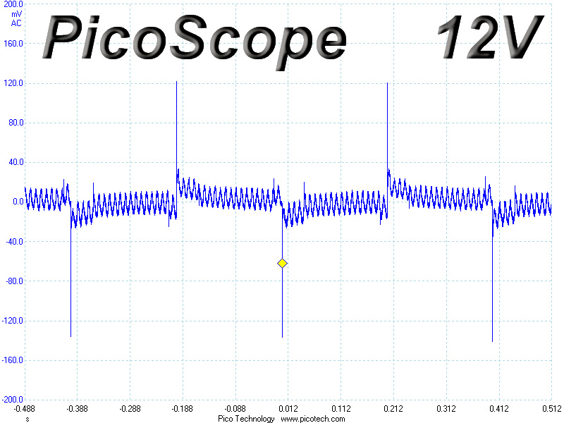
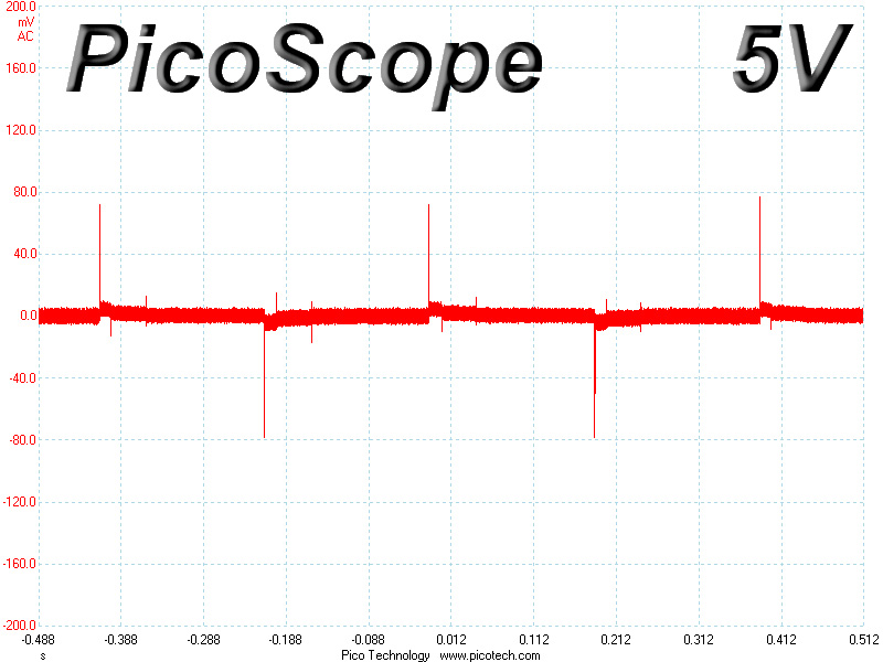
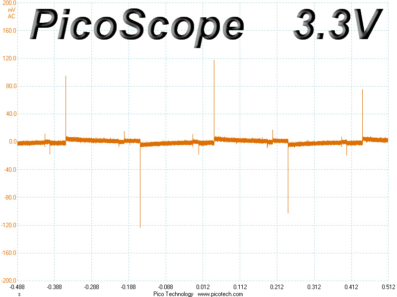
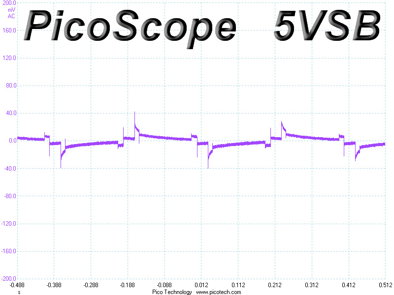
Below, you will find the oscilloscope screenshots that we took during Advanced Transient Response Testing.
Transient Response at 20% Load
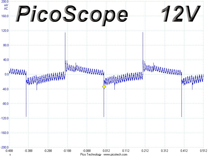
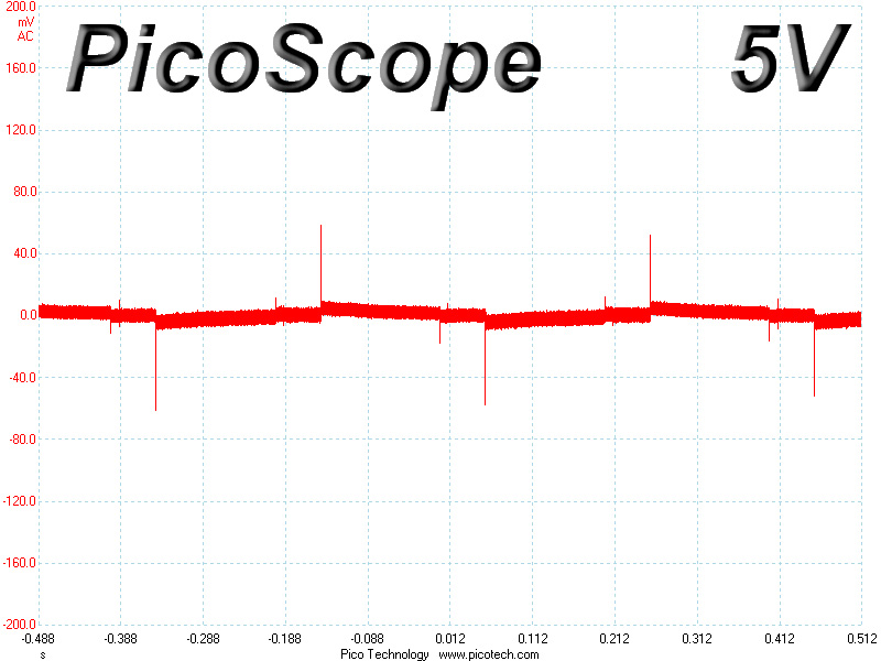
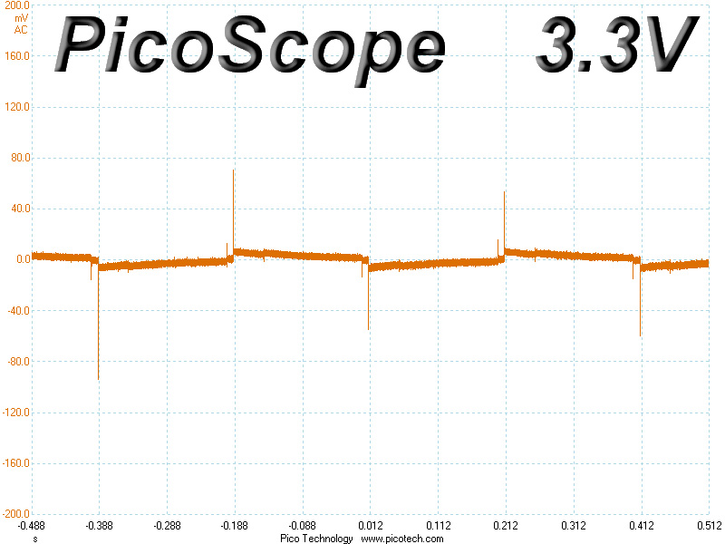
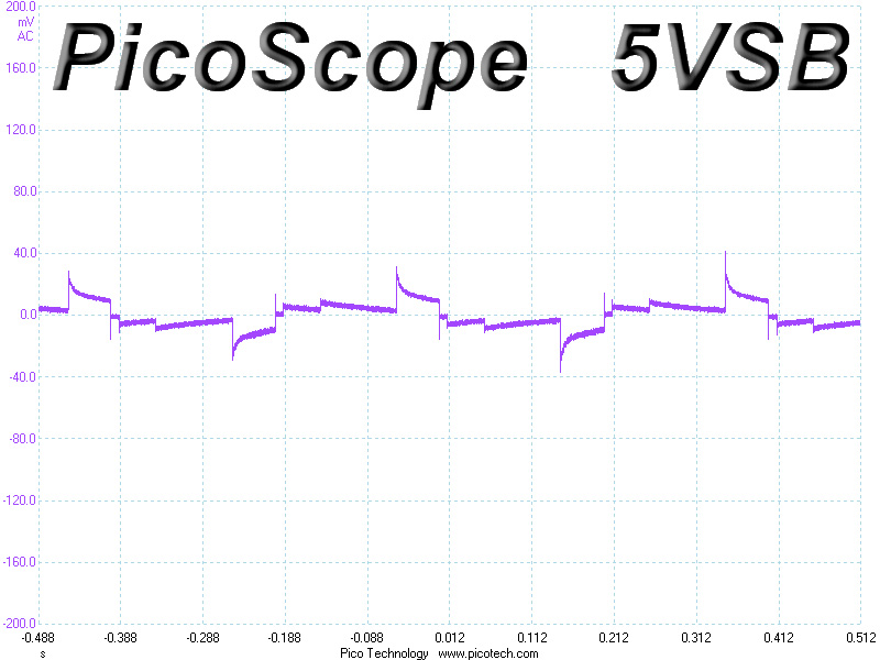
Transient Response at 50% Load
Turn-On Transient Tests
We measure the response of the PSU in simpler scenarios of transient loads - during the power-on phase of the PSU - in the next set of tests. In the first test, we turn the PSU off, dial the maximum current that the 5VSB can output, and then switch on the PSU. In the second test, we dial the maximum load that +12V can handle and we start the PSU, all while the PSU is in standby mode. In the last test, while the PSU is completely switched off (we cut off power or switch off the PSU's on/off switch), we dial the maximum load that the +12V rail can handle before switching the PSU on from the loader and restoring power. The ATX specification states that recorded spikes on all rails should not exceed 10% of their nominal values (e.g., +10% for 12V is 13.2V and for 5V is 5.5V).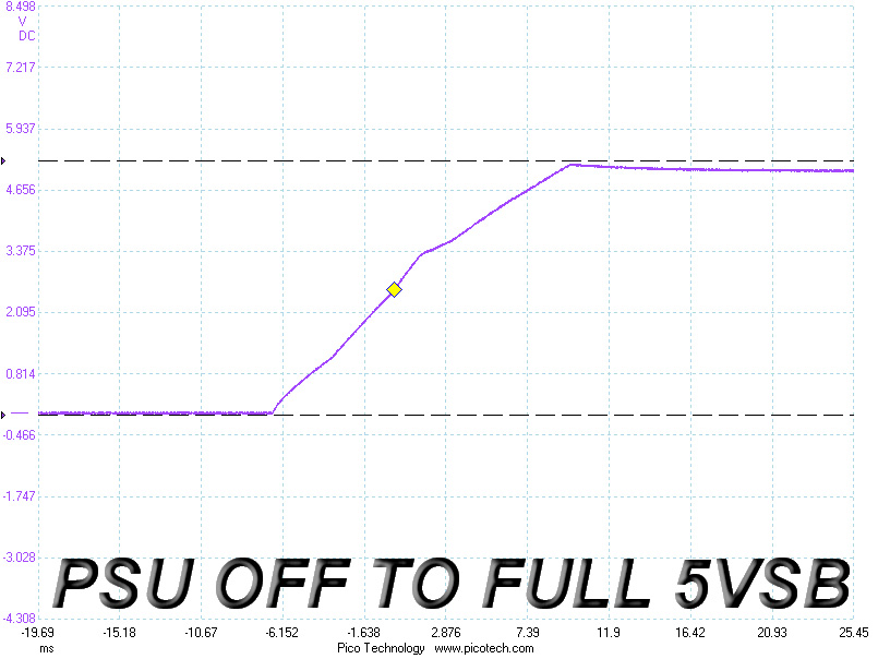
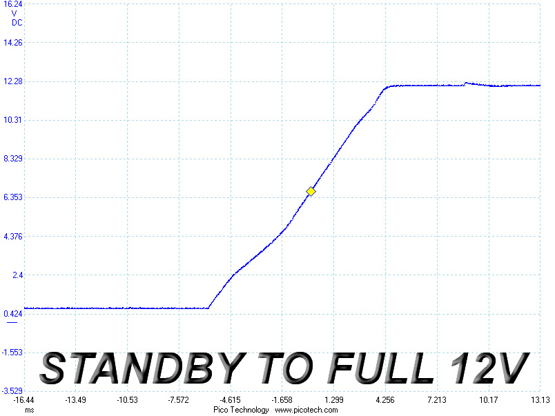
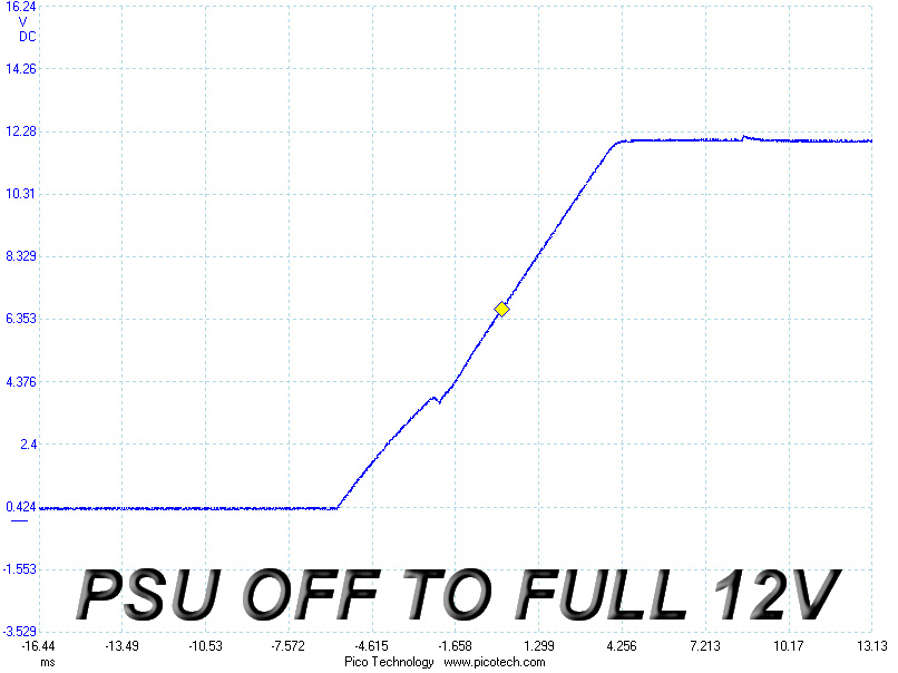
The spike at 5VSB is minimal and under the rail's nominal voltage, and the rise time is within the specified range (0.2 - 20 ms). There are no voltage overshoots on the +12V rail and only during the last test did the +12V rail register a tiny step/dive at around 4 V. All in all, the unit performed very well on these tests.
Jul 2nd, 2025 23:49 CDT
change timezone
Latest GPU Drivers
New Forum Posts
- Will you buy a RTX 5090? (589)
- NVIDIA App (36)
- AMD RX 7000 series GPU Owners' Club (1327)
- What's your latest tech purchase? (24189)
- RDNA 4 Fine Wine? (HUB Vid) (41)
- GravityMark v1.89 GPU Benchmark (308)
- Good time in the year to buy a new PC (5)
- The Official Thermal Interface Material thread (1767)
- What Windows is overall the best to you and why? (262)
- Nvidia drivers (6)
Popular Reviews
- ASUS ROG Crosshair X870E Extreme Review
- Crucial T710 2 TB Review - Record-Breaking Gen 5
- Sapphire Radeon RX 9060 XT Pulse OC 16 GB Review - An Excellent Choice
- PowerColor ALPHYN AM10 Review
- Upcoming Hardware Launches 2025 (Updated May 2025)
- AMD Ryzen 7 9800X3D Review - The Best Gaming Processor
- AVerMedia CamStream 4K Review
- Sapphire Radeon RX 9070 XT Nitro+ Review - Beating NVIDIA
- NVIDIA GeForce RTX 5060 8 GB Review
- AMD Ryzen 9 9950X3D Review - Great for Gaming and Productivity
TPU on YouTube
Controversial News Posts
- Intel's Core Ultra 7 265K and 265KF CPUs Dip Below $250 (288)
- NVIDIA Grabs Market Share, AMD Loses Ground, and Intel Disappears in Latest dGPU Update (212)
- Some Intel Nova Lake CPUs Rumored to Challenge AMD's 3D V-Cache in Desktop Gaming (140)
- NVIDIA GeForce RTX 5080 SUPER Could Feature 24 GB Memory, Increased Power Limits (114)
- NVIDIA Launches GeForce RTX 5050 for Desktops and Laptops, Starts at $249 (105)
- Microsoft Partners with AMD for Next-gen Xbox Hardware (105)
- Intel "Nova Lake‑S" Series: Seven SKUs, Up to 52 Cores and 150 W TDP (100)
- NVIDIA DLSS Transformer Cuts VRAM Usage by 20% (96)