 8
8
Super Flower Leadex III ARGB Gold 650 W Review
Voltage Regulation Stability & Ripple »Component Analysis
Before reading this page, we strongly suggest a look at this article, which will help you understand the insides of a PSU better.| Super Flower SF-650F14RG Parts Description | |
|---|---|
| General Data | |
| Manufacturer (OEM) | Super Flower |
| Platform Model | Leadex III |
| PCB Type | Single Sided |
| Primary Side | |
| Transient Filter | 3x Y caps, 3x X caps, 2x CM chokes, 1x MOV |
| Bridge Rectifier(s) | 1x |
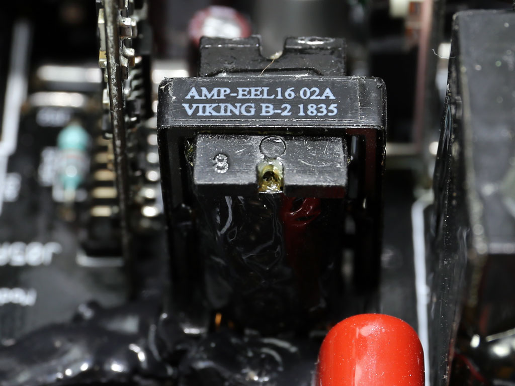
| Inrush Current Protection | NTC thermistor & relay |
| APFC MOSFETs | 2x Infineon IPA50R199CP (550 V, 11 A @ 100 °C, 0.199 ohm) & 1x SPN5003 FET (for reduced no-load consumption) |
| APFC Boost Diode | 1x STMicroelectronics STTH8R06D (600 V, 8 A @ 130 °C) |
| Hold-up Cap(s) | 1x Nippon Chemi-Con (400 V, 470 uF, 2,000 h @ 105 °C KMQ) |
| Main Switchers | 2x Infineon IPA50R199CP (550 V, 11 A @ 100 °C, 0.199 ohm) |
| APFC Controller | SF29603 & S9602 |
| Resonant Controller | SF29605 |
| Topology | Primary side: Half-bridge & LLC converter Secondary side: Synchronous rectification & DC-DC converters |
| Secondary Side | |
| +12V | 4x Infineon IPP041N04N (40 V, 80 A @ 100 °C, 4.1 mOhm) |
| 5V & 3.3V | |
| Filtering Capacitors | |
| Supervisor IC | SF29603 & LM339A |
| Fan Controller | STMicroelectronics STM8S003F3 |
| Fan Model | Globe Fan S1302412M (130 mm, 12 V, 0.40 A, fluid dynamic bearing fan) |
| 5VSB Circuit | |
| Rectifiers | 1x PFC Device PFR20L60CT (60 V, 20 A) |
| Standby PWM Controller | SF29604 |
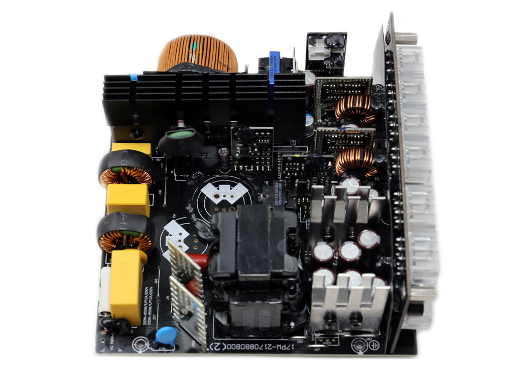
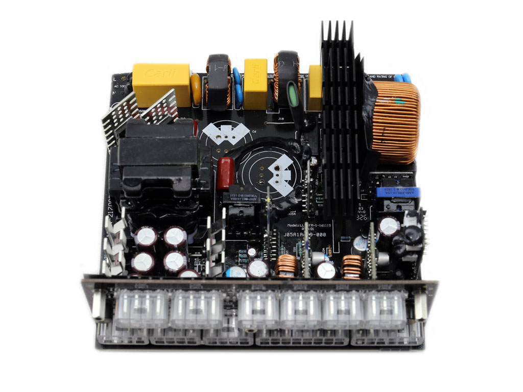
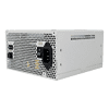
There are no significant differences between the plain Super Flower Leadex III and Leadex III ARGB platforms, besides an ARGB fan and the single semi-passive mode—as there are two in the former. On the primary side is a half-bridge topology supported by an LLC resonant converter for higher efficiency. The secondary side utilizes a synchronous rectification scheme, and the minor rails are generated through two VRMs. Soldering quality is not the best I have seen from Super Flower, but rest assured that it won't create any problems, and it doesn't seem to affect performance.
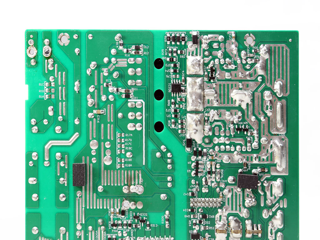
The transient filter has all the necessary parts and does a good job of suppressing both incoming and outgoing EMI.
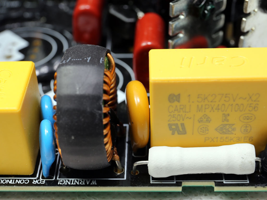
An MOV handles voltage surges, and an NTC thermistor-relay combo protects against large inrush currents.
The bridge rectifier which fully rectifies the incoming AC signal feeding the PSU's APFC converter.
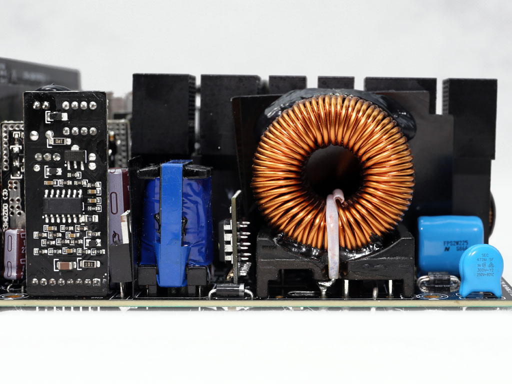
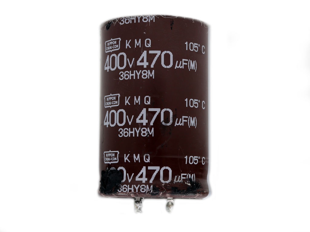
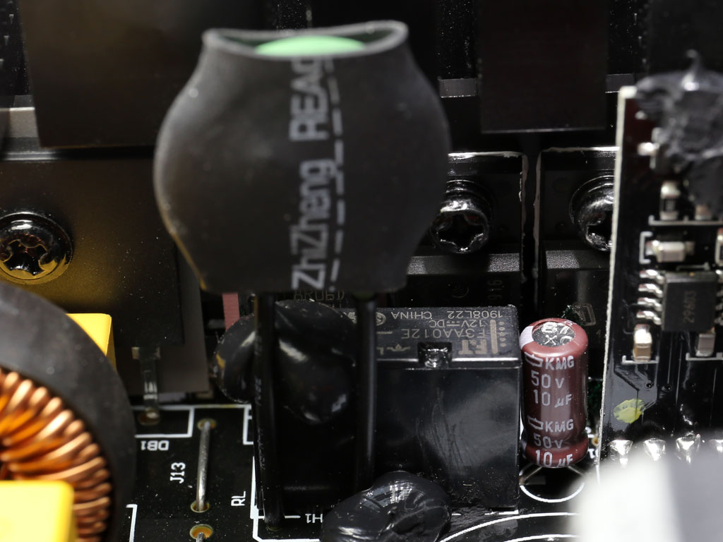
The APFC converter uses two Infineon IPA50R199CP FETs and a STTH8R06D boost diode by STMicroelectronics. The bulk cap is by Chemi-Con and has enough capacity to provide a hold up time of over 17 ms. Programming of the LLC resonant converter also plays a major role in the hold up time.
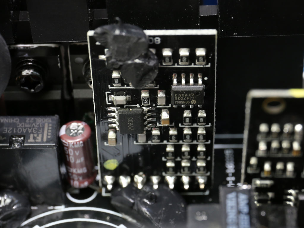
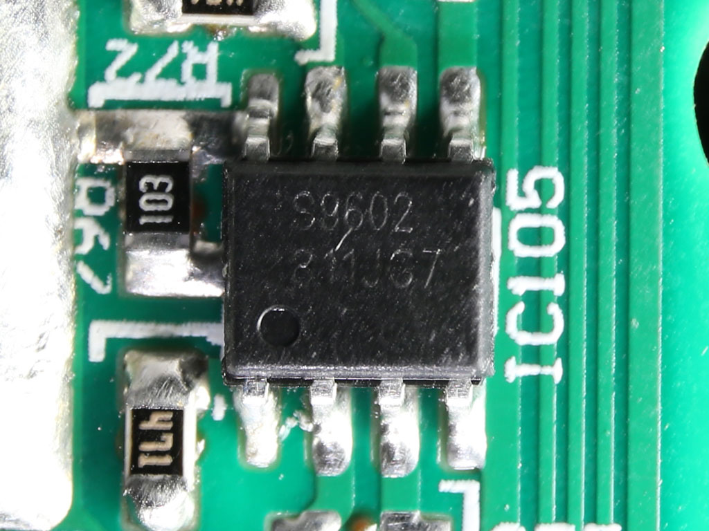
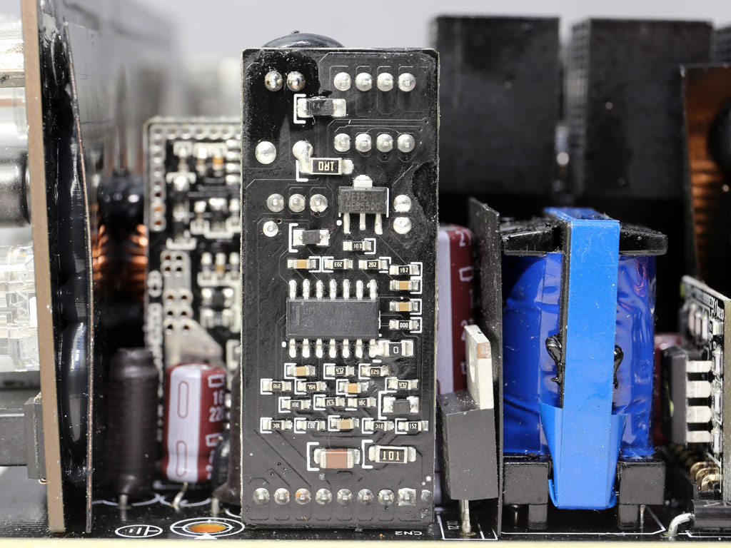
An SPN5003 FET isolates the APFC converter while the PSU is in standby to lower vampire power. On the board that hosts this FET is the APFC controller consisting of an SF29603 IC supported by another IC with model number S9602. After all this time, I still don't have any detailed information on these ICs.

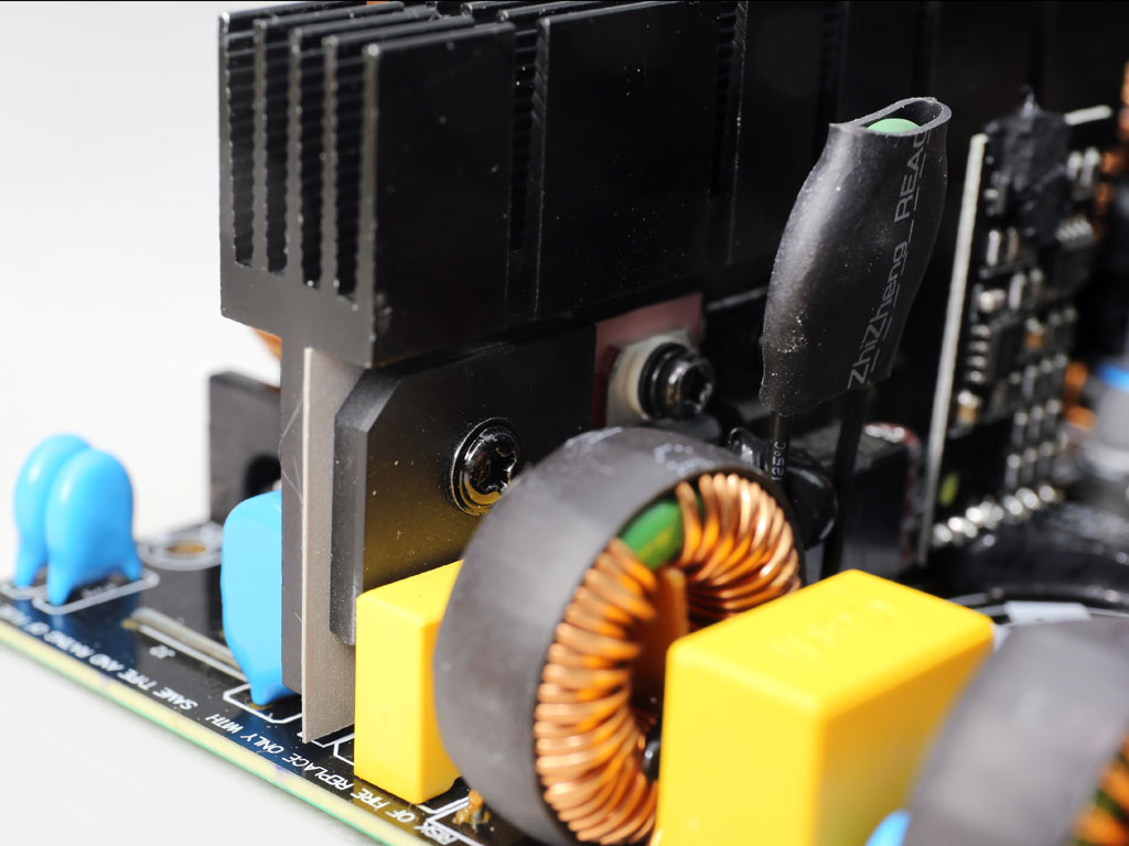
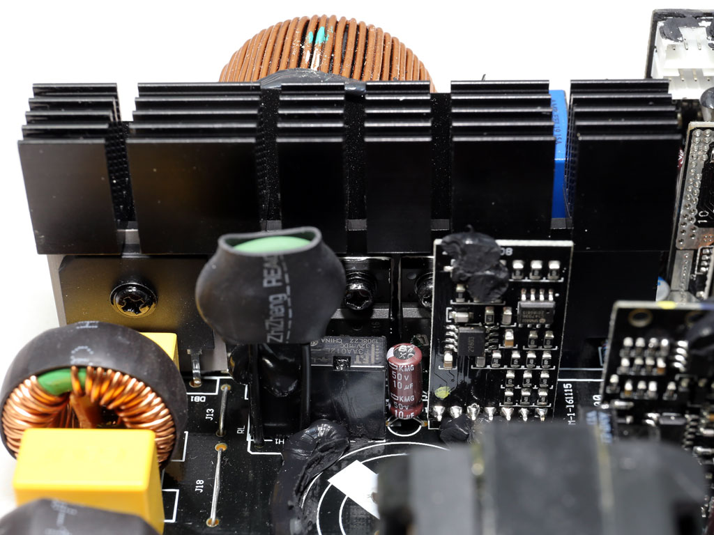
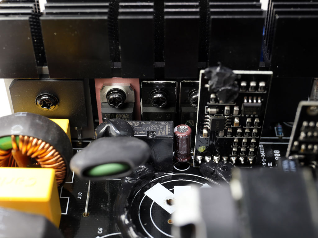
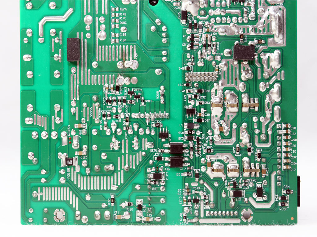
The main switching FETs are arranged in a half-bridge topology. Similar to the APFC converter, two Infineon IPA50R199CP are used in this stage.
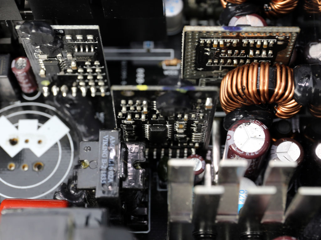
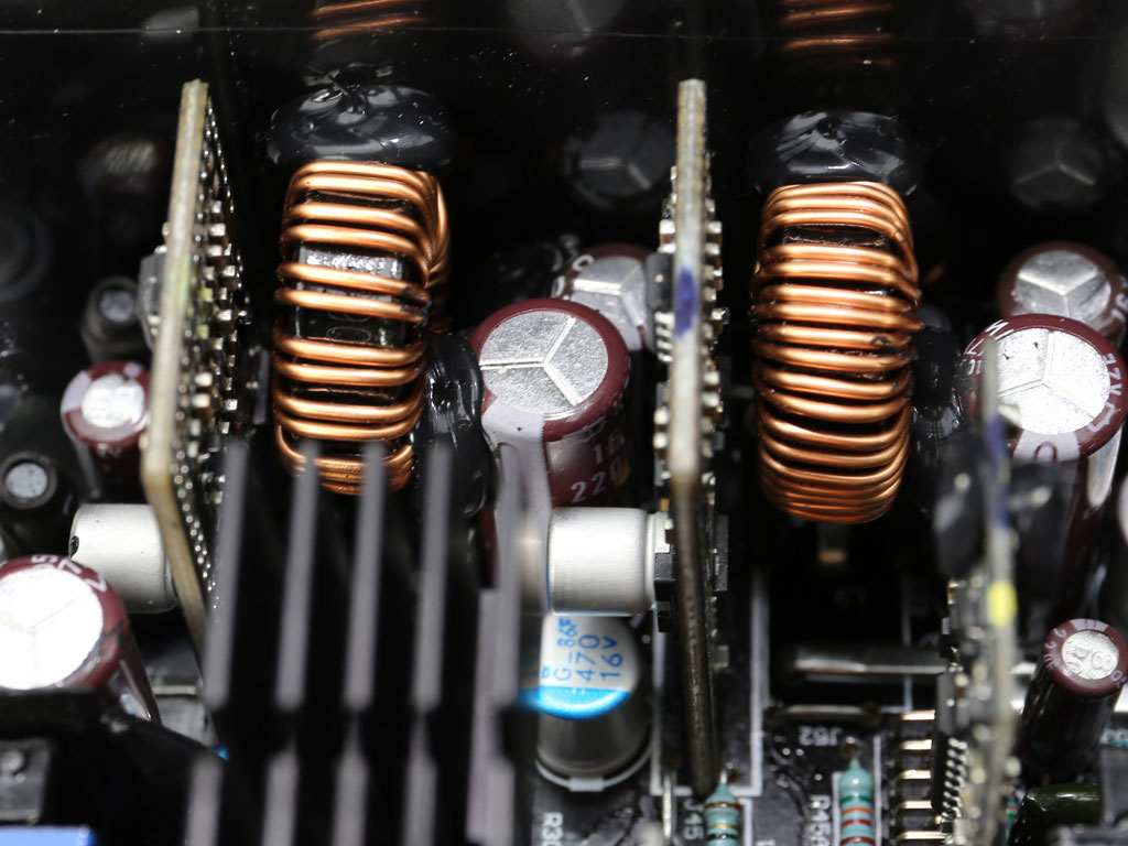
These photos depict the resonant tank and resonant controller, an SF29605 IC. The latter controls the primary switching FETs and those generating the +12 V rail.

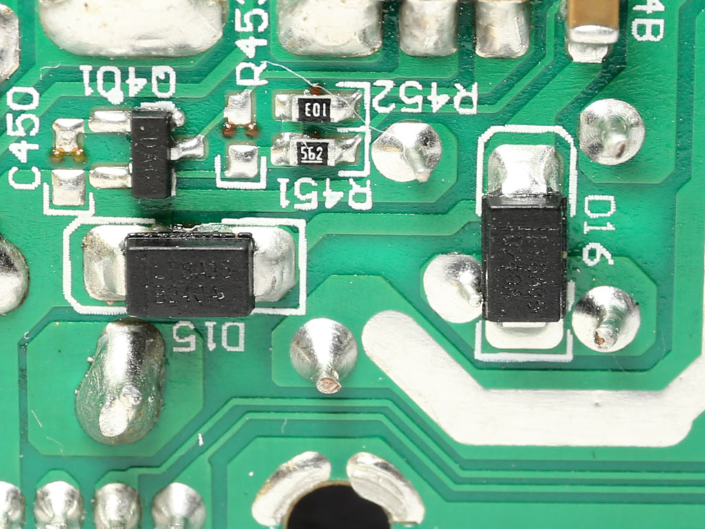
Four Infineon FETs handle the +12 V rail.
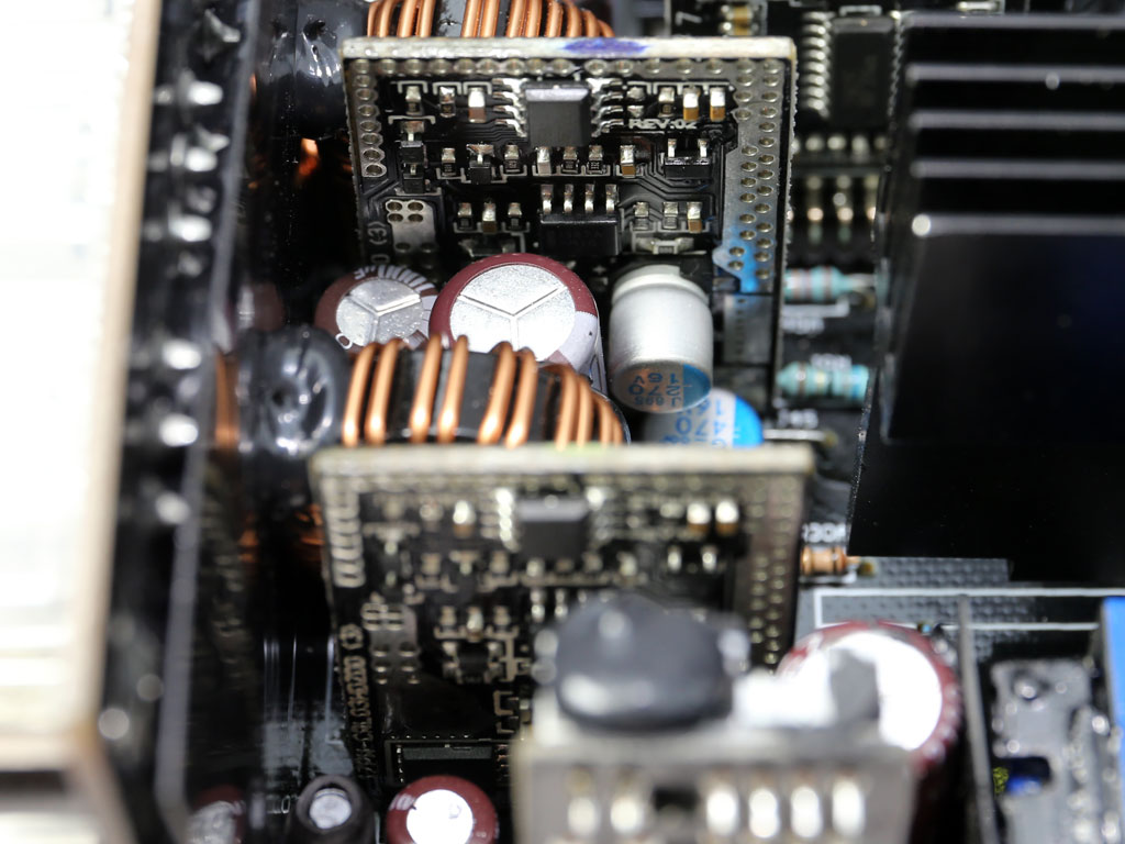
Two DC-DC converters are powered by the +12 V rail to generate the minor rails. In total, eight AON6516 FETs are used, along with a pair of NCP1587A PWM controllers.
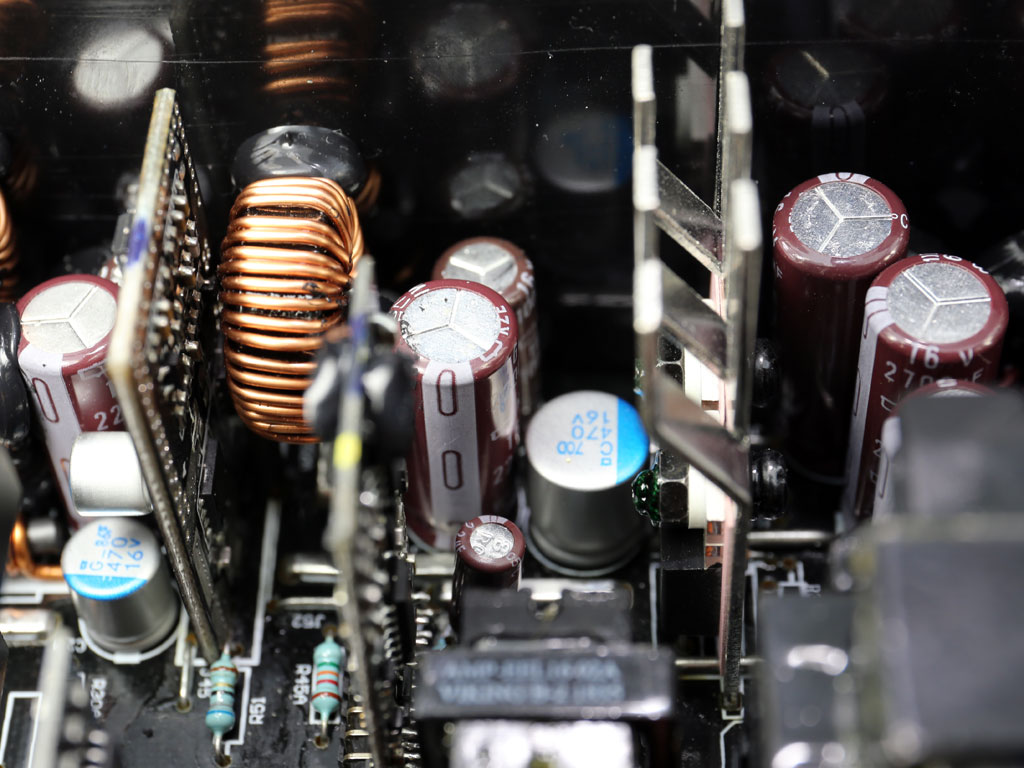
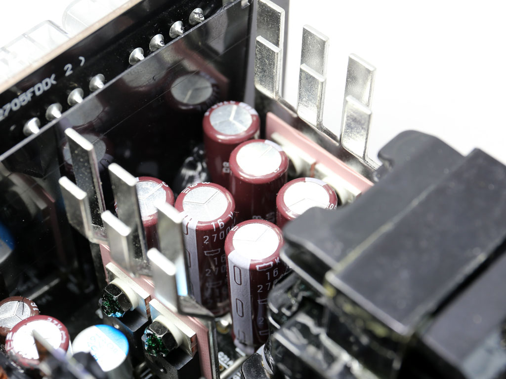
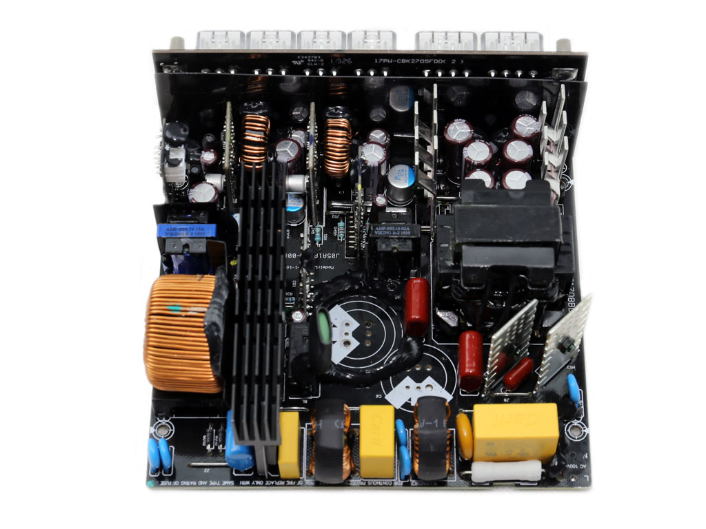
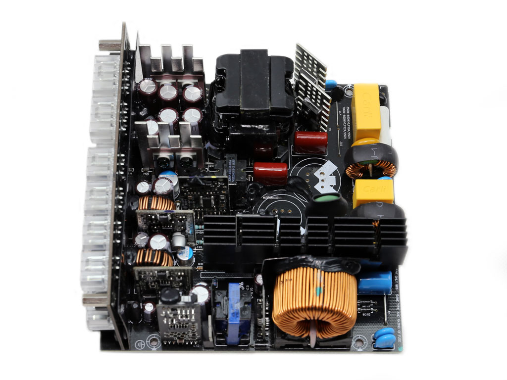
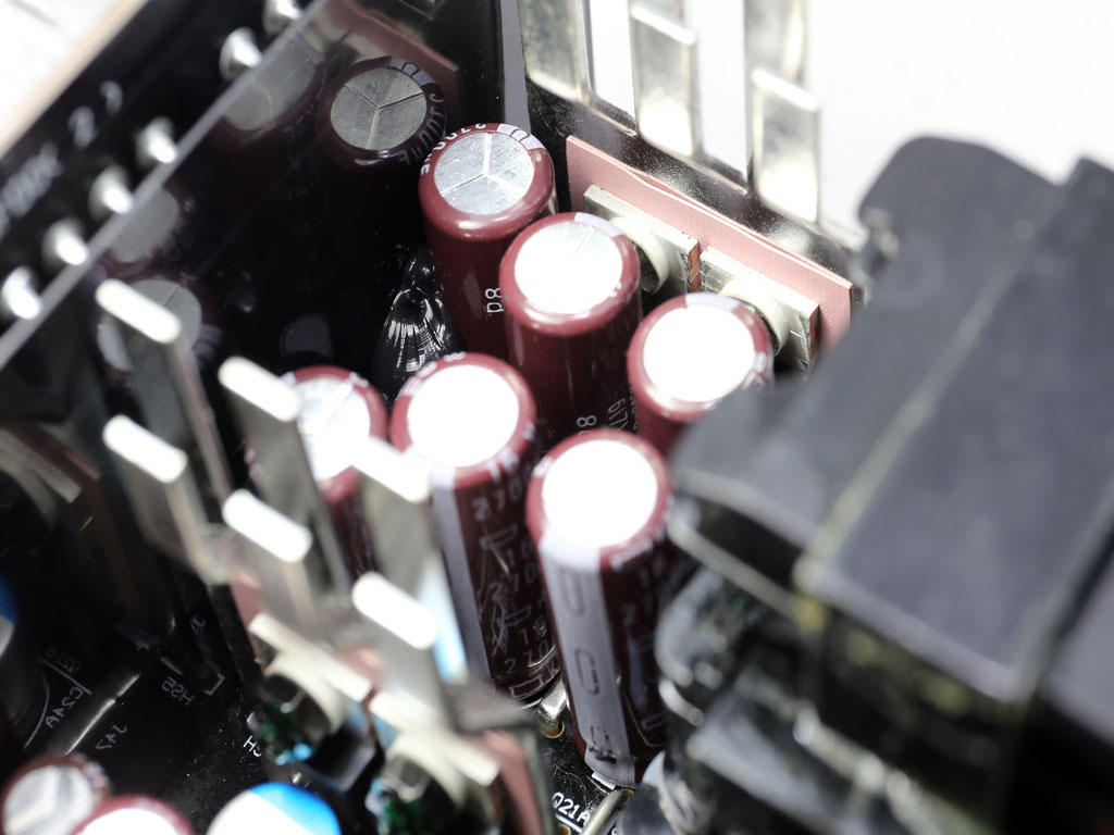
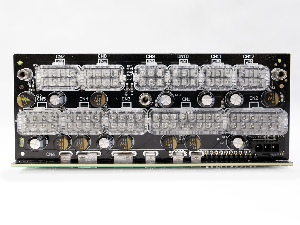
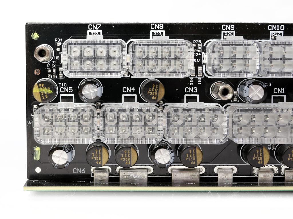
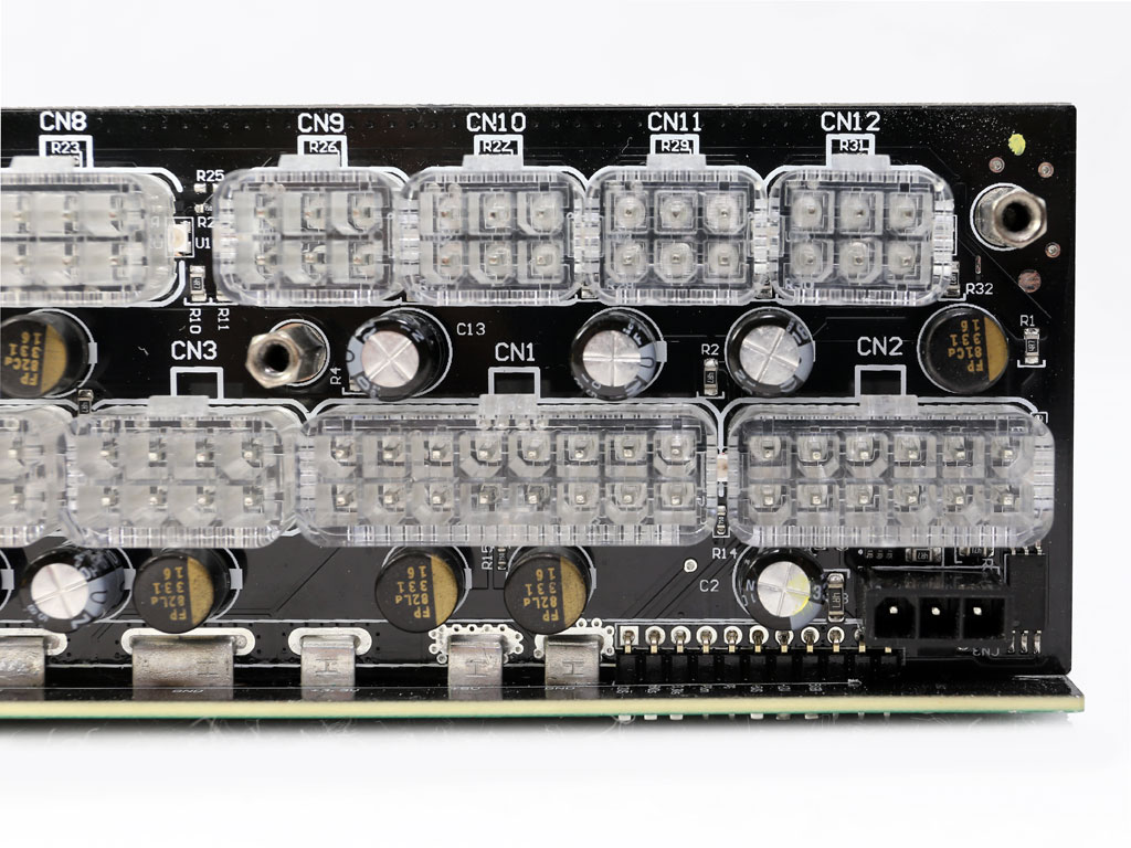
Japanese manufacturers provide all the electrolytic filtering caps. Not all of these have a high lifetime, though. The heaviest burden falls to the Chemi-Con KZE caps, which are widely used in higher-end PSUs. Besides electrolytic caps, several polymers are also used. Most of these are installed on the modular PCB.
The Nichicon RZ caps, which have a lifetime of 1000 hours at 105 °C, are installed where they won't be highly stressed, forming a second ripple-filtering layer.
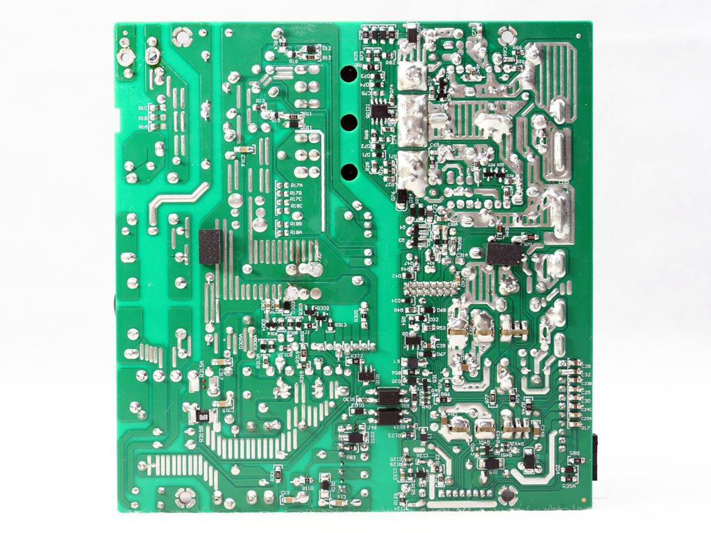
As I have already mentioned, soldering quality is not the best I have seen from Super Flower. In some areas on the secondary side, soldering look sloppy. That said, it won't create any issues.
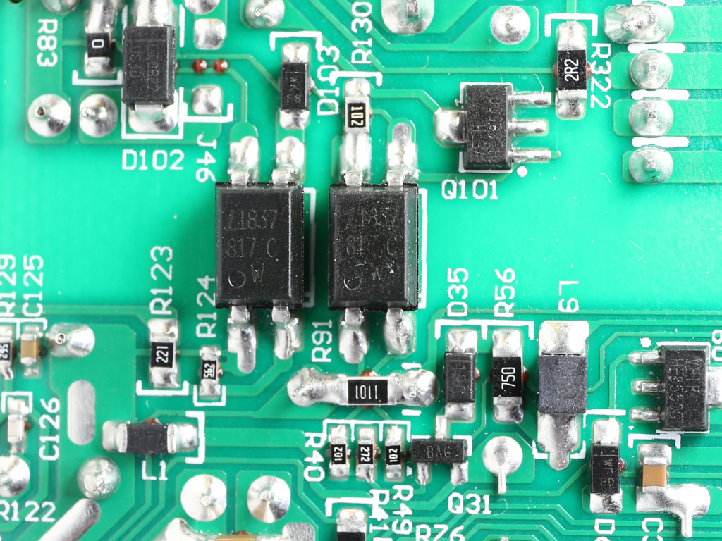
My photographer likes to shoot optocouplers, so I have to deal with these photos in every review.

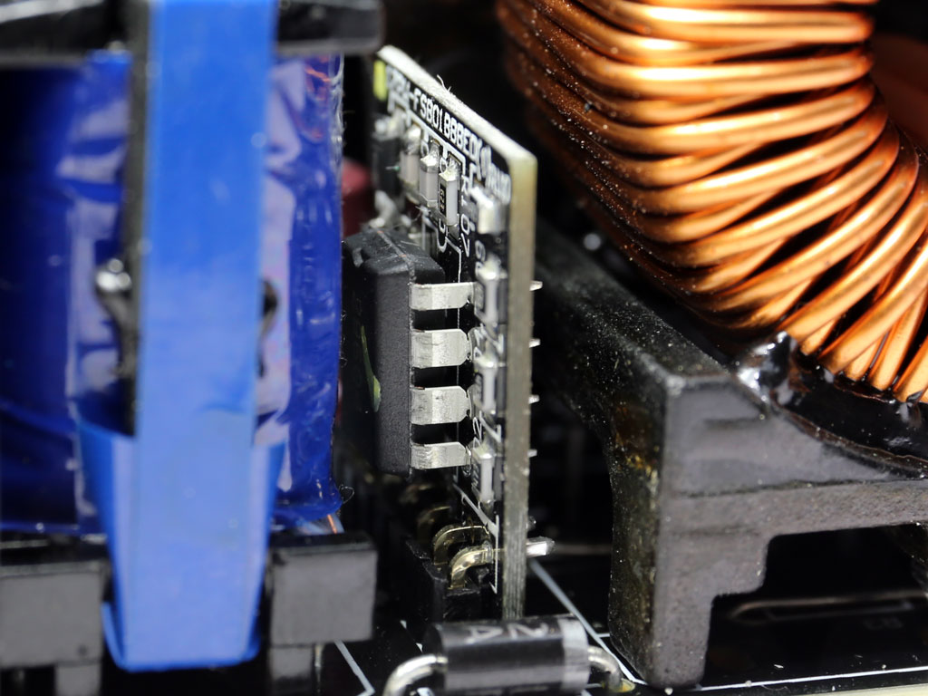
The 5VSB rectification circuit uses a PFC Device PFR20L60CT SBR on its secondary side. The standby PWM controller is an SF29604 IC.
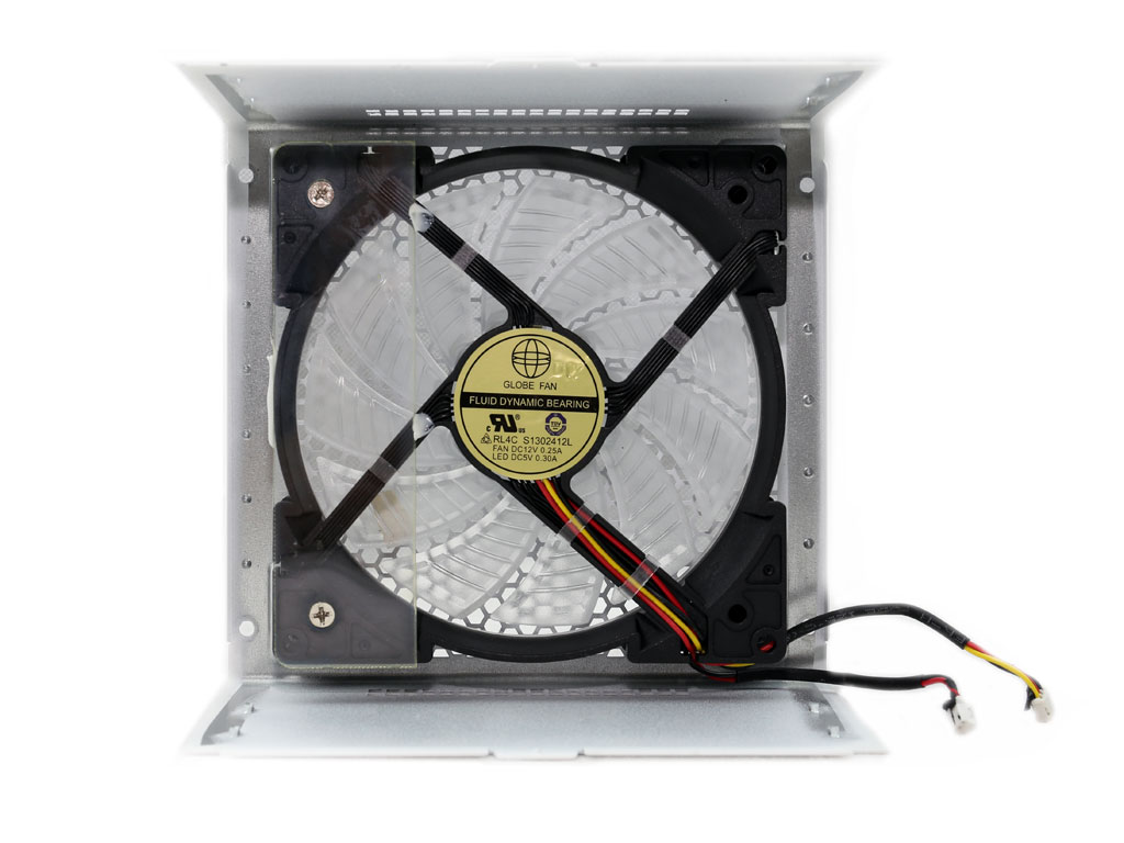
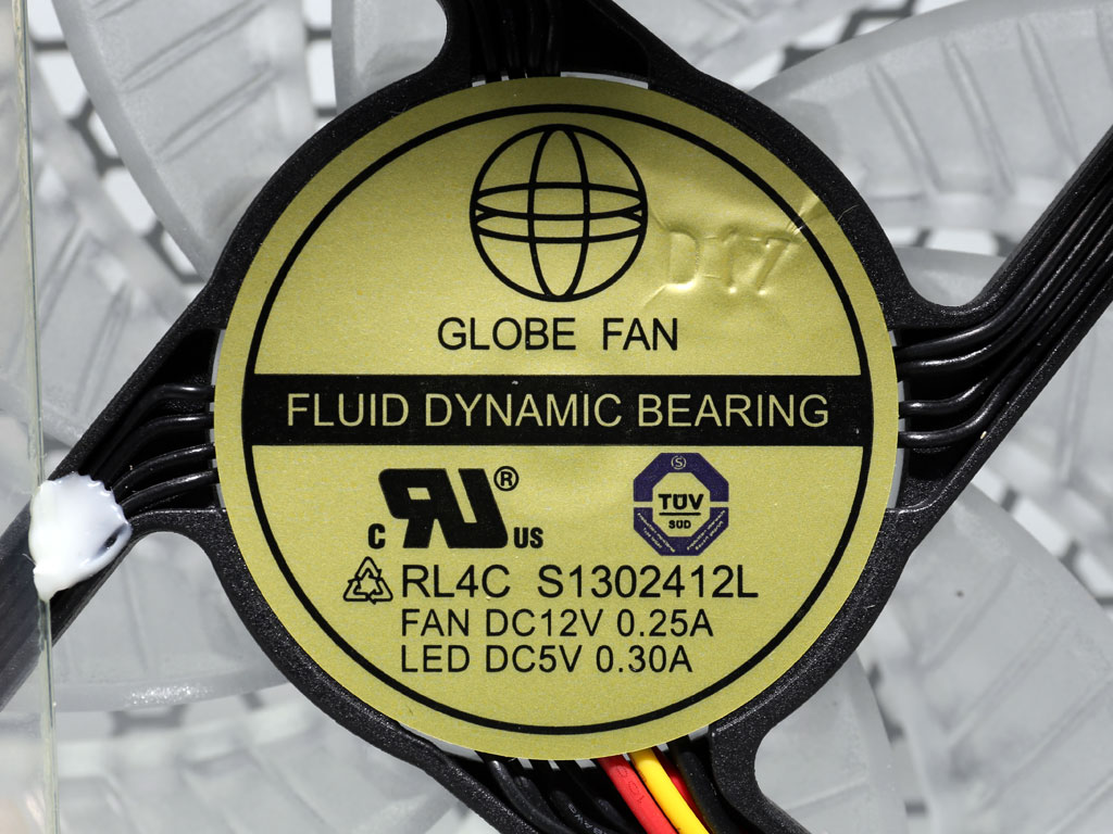
The cooling fan measures 130 mm across and uses a fluid dynamic bearing.
Feb 27th, 2025 01:04 EST
change timezone
Latest GPU Drivers
New Forum Posts
- 9800 x3d overheating what is the stock voltage (27)
- TPU's Nostalgic Hardware Club (20013)
- Help with integrated gpu. (79)
- Is ARC SLI friendly? (5)
- What are you playing? (23044)
- Mouse and keyboard function in BIOS but not in Windows 7 (18)
- [Intel AX1xx/AX2xx/AX4xx/AX16xx/BE2xx/BE17xx] Intel Modded Wi-Fi Driver with Intel® Killer™ Features (282)
- Solidigm NVMe Custom Modded Driver for All NVMe Brands SSDs & Any NVMe SSDs (216)
- RX 6600XT & ROG STRIX B460 I GAMING = black screen (9)
- AAF Optimus Modded Driver For Windows 10 & Windows 11 - Only for Realtek HDAUDIO Chips (335)
Popular Reviews
- Corsair Xeneon 34WQHD240-C Review - Pretty In White
- Corsair Virtuoso MAX Wireless Review
- ASUS GeForce RTX 5070 Ti TUF OC Review
- Gigabyte X870 Aorus Elite WiFi 7 Review
- Montech HyperFlow Silent 360 Review
- MSI GeForce RTX 5070 Ti Ventus 3X OC Review
- MSI GeForce RTX 5070 Ti Vanguard SOC Review
- AMD Ryzen 7 9800X3D Review - The Best Gaming Processor
- MSI GeForce RTX 5070 Ti Gaming Trio OC+ Review
- Montech TITAN PLA 1000 W Review
Controversial News Posts
- NVIDIA GeForce RTX 50 Cards Spotted with Missing ROPs, NVIDIA Confirms the Issue, Multiple Vendors Affected (496)
- AMD Radeon 9070 XT Rumored to Outpace RTX 5070 Ti by Almost 15% (304)
- AMD Plans Aggressive Price Competition with Radeon RX 9000 Series (274)
- AMD Radeon RX 9070 and 9070 XT Listed On Amazon - One Buyer Snags a Unit (247)
- NVIDIA Investigates GeForce RTX 50 Series "Blackwell" Black Screen and BSOD Issues (244)
- Edward Snowden Lashes Out at NVIDIA Over GeForce RTX 50 Pricing And Value (241)
- AMD Denies Radeon RX 9070 XT $899 USD Starting Price Point Rumors (239)
- AMD Mentions Sub-$700 Pricing for Radeon RX 9070 GPU Series, Looks Like NV Minus $50 Again (199)