 5
5
Xigmatek Vector P Series 700 W Review
Ripple Measurements »Advanced Transient Response Tests
In these tests, we monitor the response of the PSU in two different scenarios. First, a transient load (10 A at +12V, 5 A at 5V, 5 A at 3.3V, and 0.5 A at 5VSB) is applied to the PSU for 200 ms while the latter is working at a 20% load. In the second scenario, the PSU, while working at 50% load, is hit by the same transient load. We measure the voltage drops the transient load causes in both tests using our oscilloscope. The voltages should remain within the regulation limits defined by the ATX specification. We must stress here that the above tests are crucial since they simulate transient loads a PSU is very likely to handle (e.g., booting a RAID array, an instant 100% load of CPU/VGAs, etc.). We call these tests "Advanced Transient Response Tests", and they are designed to be very tough to master, especially for PSUs with a capacity below 500 W.| Advanced Transient Response 20% | ||||
|---|---|---|---|---|
| Voltage | Before | After | Change | Pass/Fail |
| 12 V | 12.200V | 11.841V | 2.94% | Pass |
| 5 V | 5.001V | 4.903V | 1.96% | Pass |
| 3.3 V | 3.332V | 3.225V | 3.21% | Pass |
| 5VSB | 4.981V | 4.906V | 1.51% | Pass |
| Advanced Transient Response 50% | ||||
|---|---|---|---|---|
| Voltage | Before | After | Change | Pass/Fail |
| 12 V | 12.148V | 12.022V | 1.04% | Pass |
| 5 V | 4.966V | 4.867V | 1.99% | Pass |
| 3.3 V | 3.305V | 3.169V | 4.11% | Pass |
| 5VSB | 4.942V | 4.870V | 1.46% | Pass |
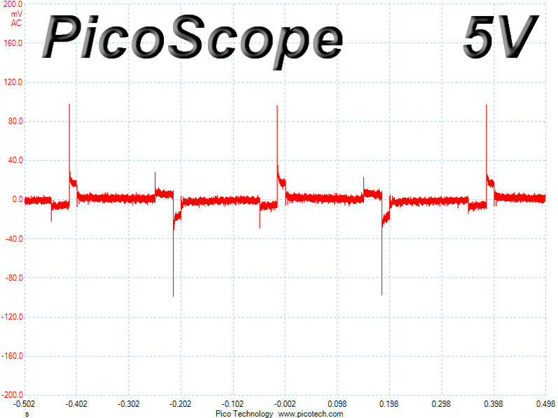
The +12 V rail registered high deviations during the first test because it was operating in PWM mode, but deviations on the same rail dropped down to nearly 1% in the second test. The 3.3V rail didn't perform well here since it dropped its voltage very close to the lower limit during the second test, while the other two rails (5V and 5VSB) performed decently.
You will find the oscilloscope screenshots we took during Advanced Transient Response Testing below.
Transient Response at 20% Load
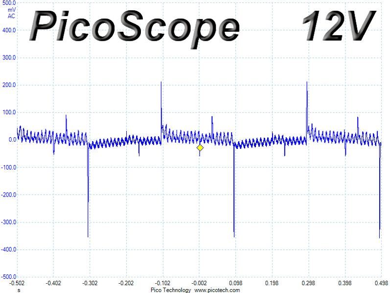


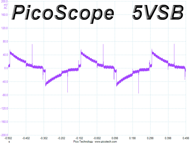
Transient Response at 50% Load


Turn-On Transient Tests
We measure the response of the PSU in simpler scenarios of transient loads—during the power-on phase of the PSU—in the next set of tests. In the first test, we turn the PSU off, dial the maximum current the 5VSB can output, and then switch on the PSU. In the second test, we dial the maximum load +12V can handle and start the PSU while the PSU is in standby mode. In the last test, while the PSU is completely switched off (we cut off power or switch off the PSU's on/off switch), we dial the maximum load +12V can handle before switching the PSU on from the loader and restoring power. The ATX specification states that recorded spikes on all rails should not exceed 10% of their nominal values (e.g., +10% for 12V is 13.2V and 5.5V for 5V).
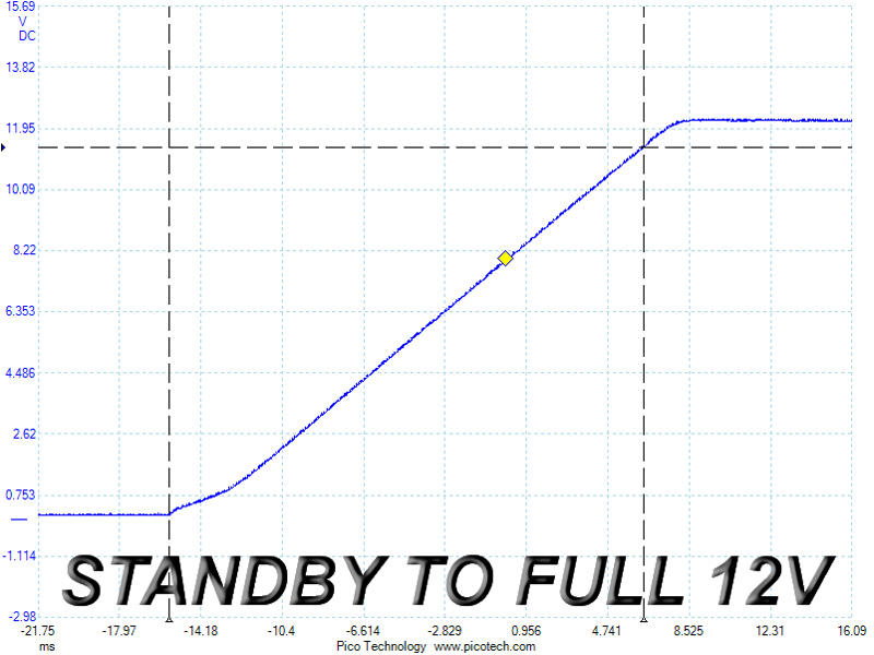
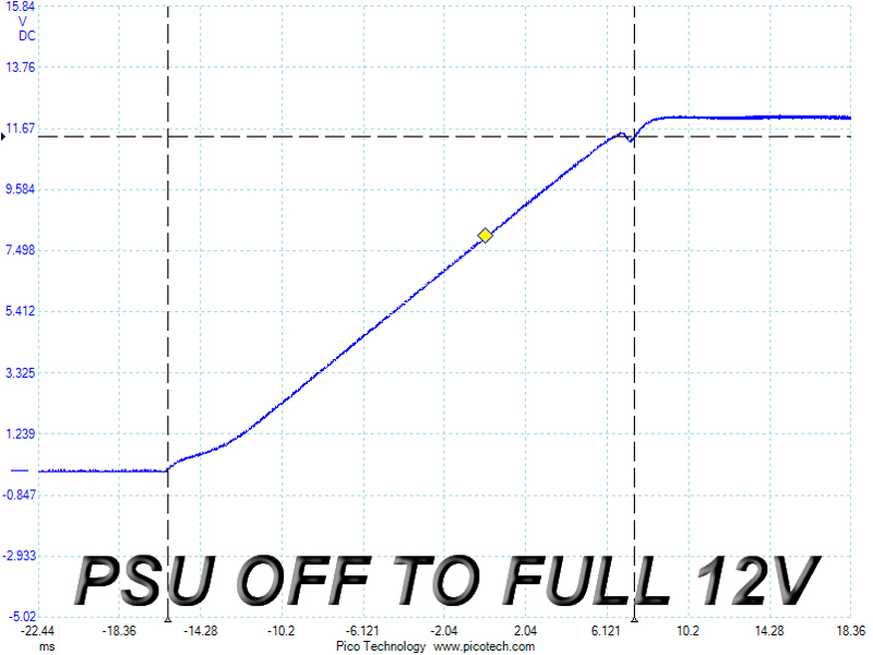
The 5VSB rail registered a noticeable voltage overshoot which, however, was below the 5.5 V upper limit, though it exceeded the 20 ms rise time limit by a few ms in the other two tests.
Jan 10th, 2025 08:34 EST
change timezone
Latest GPU Drivers
New Forum Posts
- Dual AMD GPU System Problem (3)
- win 10 pro or win 11 ?!.. (5)
- MSI N770-2GD5/OC - latest bios (1)
- Can I mix 16 GB and 32 GB RAM (DDR5) in a laptop? (7)
- Best time to sell your used 4090s is now. (175)
- Are people planning an upgrade? (226)
- The TPU UK Clubhouse (25559)
- TechPowerUp Screenshot Thread (MASSIVE 56K WARNING) (4247)
- (Simple, Explanation) How to make RX 580 work with M91p (1)
- What was lacking GPU-wise at this year's CES (116)
Popular Reviews
- ASUS ROG Strix B850-F Gaming WiFi Review
- AMD Ryzen 7 9800X3D Review - The Best Gaming Processor
- Royal Kludge S85 TKL Wireless Mechanical Keyboard Review
- HEDDphone TWO GT Air Motion Transformer Headphones Review
- LAMZU Maya X Review
- DDR5 Thermal Testing & Analysis
- GPU Test System Update for 2025
- Call of Duty: Black Ops 6 Performance Benchmark Review - AMD FTW
- Upcoming Hardware Launches 2024 (Updated Nov 2024)
- Intel Arc B580 Review - Excellent Value
Controversial News Posts
- NVIDIA 2025 International CES Keynote: Liveblog (449)
- AMD Debuts Radeon RX 9070 XT and RX 9070 Powered by RDNA 4, and FSR 4 (340)
- NVIDIA GeForce RTX 5090 Features 575 W TDP, RTX 5080 Carries 360 W TDP (212)
- AMD Radeon RX 9070 XT Alleged Benchmark Leaks, Underwhelming Performance (204)
- Potential RTX 5090 and RTX 5080 Pricing in China Leaks (173)
- 32 GB NVIDIA RTX 5090 To Lead the Charge As 5060 Ti Gets 16 GB Upgrade and 5060 Still Stuck With Last-Gen VRAM Spec (173)
- AMD Radeon RX 9070 XT Boosts up to 3.10 GHz, Board Power Can Reach up to 330W (167)
- NVIDIA GeForce RTX 5070 Ti Leak Tips More VRAM, Cores, and Power Draw (161)