 7
7
ASRock X299E-ITX/ac Motherboard Review
BIOS Overview »Board Layout
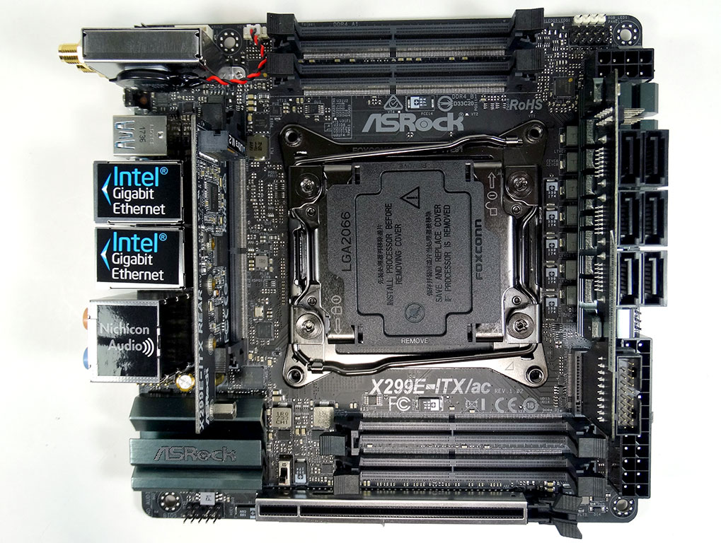
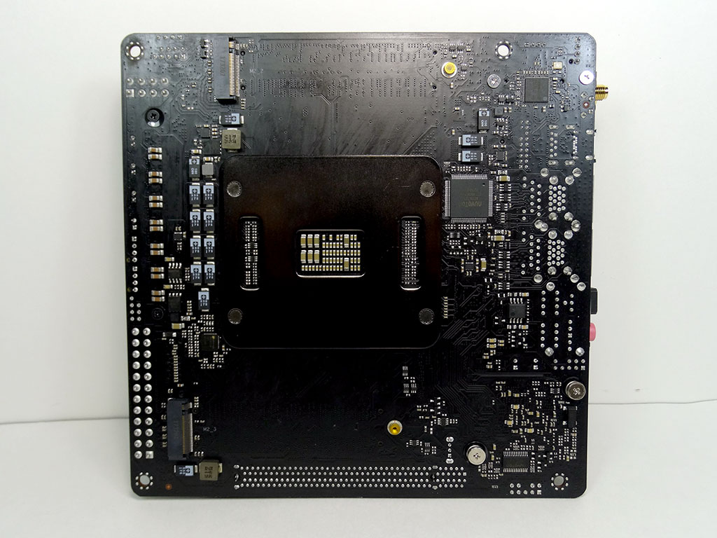
With a board this small, and a socket this big, it is only natural that everything seems to all be crammed together. Even the back of the board has a fair bit of stuff on it.
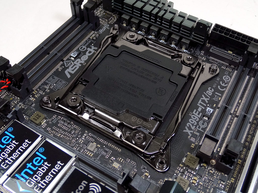
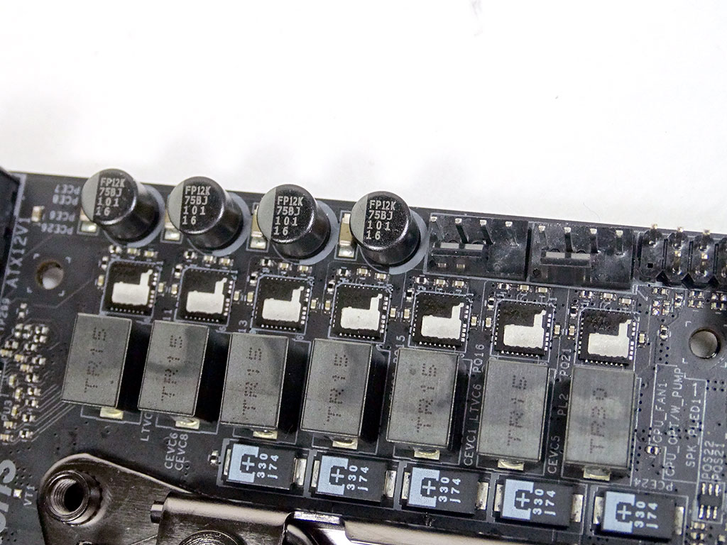
The socket itself is closely guarded by SO-DIMM slots, the VRM and the board's rear I/O panel. That VRM is a 7-phase design; each phase is capable of 60A.
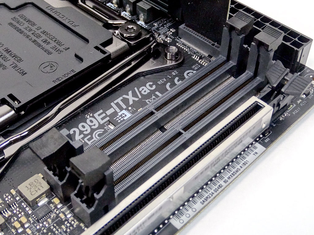

The four SO-DIMM slots that flank either side of the socket support up to 4000 MHz memory, but you'll have a hard time finding 4000 MHz SO-DIMMs. All four slots are aligned in the same orientation, even though they sit on either side of the socket. This board's maximum memory capacity is 64 GB.
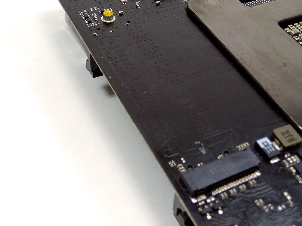
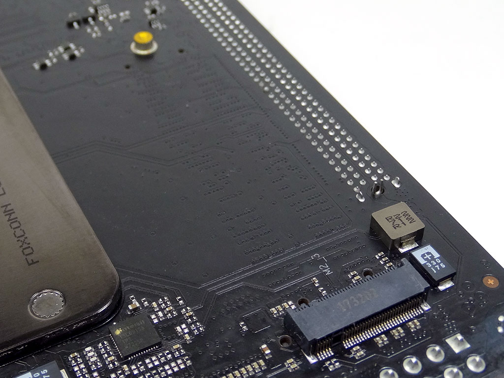
The rear of the board carries dual M.2 ports, one on either side of the board's backplate. These ports only support PCIe-based M.2 devices of the 2280 variety. Most high-performance NVME drives are of this form factor right now, so the singular size is not a big deal right at this moment, but that could change in the future.
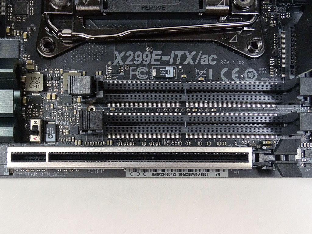

For PCIe expansion, you are provided with a single PCIe 3.0 x16 slot. Given the form factor, this is standard-fare. The rear I/O has antenna ports, USB 3.1 Gen1 and Gen2 ports, audio, and dual LAN ports. There is also a single button that can be used as either a power or Clear CMOS button. A switch is provided to swap what this button does, and that switch is just above the PCIe slot, next to the chipset cooler. That means it is accessible even after you have the board installed and all filled up.
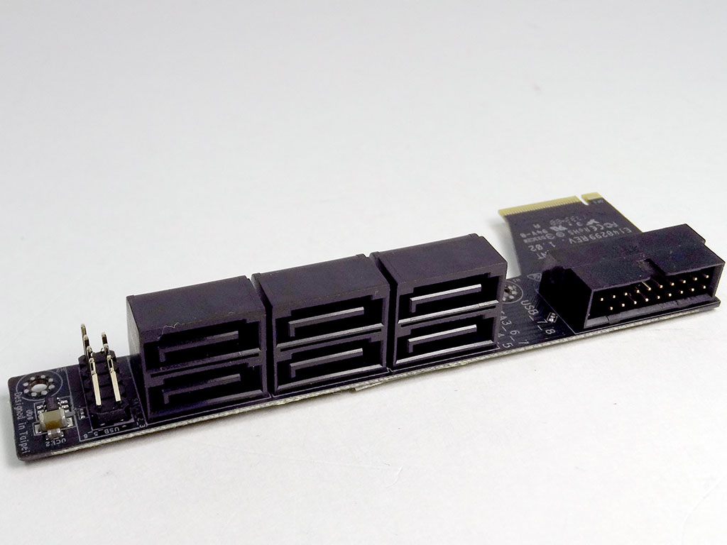
Due to the small form factor, adding in all this functionality isn't exactly possible within the confines of the main PCB. To fix that, ASRock has two additional PCBs that connect to the board via different sockets. One sits on the front of the board, and the other is on the rear, next to the rear I/O ports. The PCB at the front uses a specialized socket and carries the SATA ports, a USB 2.0 header, and a USB 3.0 header.
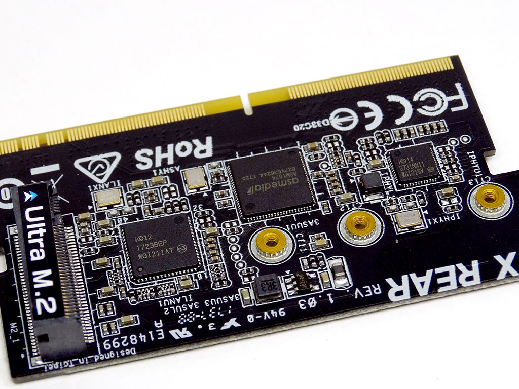
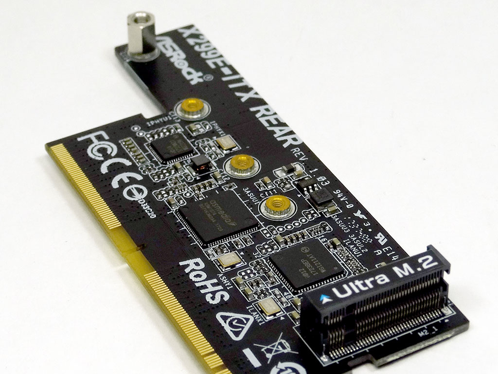
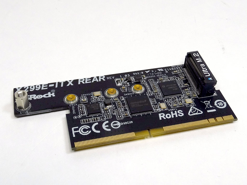
The rear card is quite different. It fits into a special SO-DIMM slot and carries the LAN chips and a USB hub. If you decide you don't want this mini-board, you'll disable the LAN ports and the USB 3.1 Gen1 ports on the rear I/O panel. The add-in card also carries the main M.2 slot (supports M Key type 2230/2242/2260/2280), which supports both PCIe and SATA devices. Having these options is kind of nice for those who want to minimize how many system components there are since you can simply pull the cards from the board and have that added space for perhaps a cooler, or whatever else you may like.
Jul 5th, 2025 16:22 CDT
change timezone
Latest GPU Drivers
New Forum Posts
- Do you use Linux? (677)
- Optane performance on AMD vs Intel (58)
- Frametime spikes and stuttering after switching to AMD CPU? (521)
- Stalker 2 is looking great. (187)
- b550m aorus elite not posting with new ram (7)
- Gigabyte graphic cards - TIM gel SLIPPAGE problem (131)
- Can you guess Which game it is? (203)
- How do you view TPU & the internet in general? (With poll) (74)
- EVGA XC GTX 1660 Ti 8GB ROM (9)
- What are you playing? (23892)
Popular Reviews
- NVIDIA GeForce RTX 5050 8 GB Review
- Fractal Design Scape Review - Debut Done Right
- Crucial T710 2 TB Review - Record-Breaking Gen 5
- ASUS ROG Crosshair X870E Extreme Review
- PowerColor ALPHYN AM10 Review
- Sapphire Radeon RX 9060 XT Pulse OC 16 GB Review - An Excellent Choice
- Upcoming Hardware Launches 2025 (Updated May 2025)
- AMD Ryzen 7 9800X3D Review - The Best Gaming Processor
- Sapphire Radeon RX 9070 XT Nitro+ Review - Beating NVIDIA
- NVIDIA GeForce RTX 5060 8 GB Review
TPU on YouTube
Controversial News Posts
- Intel's Core Ultra 7 265K and 265KF CPUs Dip Below $250 (288)
- NVIDIA Grabs Market Share, AMD Loses Ground, and Intel Disappears in Latest dGPU Update (212)
- Some Intel Nova Lake CPUs Rumored to Challenge AMD's 3D V-Cache in Desktop Gaming (140)
- NVIDIA GeForce RTX 5080 SUPER Could Feature 24 GB Memory, Increased Power Limits (115)
- Microsoft Partners with AMD for Next-gen Xbox Hardware (105)
- NVIDIA Launches GeForce RTX 5050 for Desktops and Laptops, Starts at $249 (105)
- AMD Radeon RX 9070 XT Gains 9% Performance at 1440p with Latest Driver, Beats RTX 5070 Ti (102)
- Intel "Nova Lake‑S" Series: Seven SKUs, Up to 52 Cores and 150 W TDP (100)