 8
8
Be Quiet Dark Power Pro 10 550 W Review
Ripple Measurements »Advanced Transient Response Tests
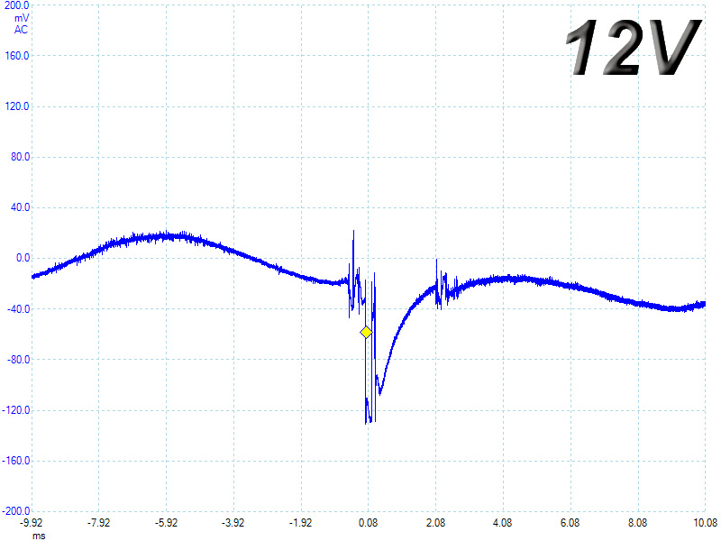
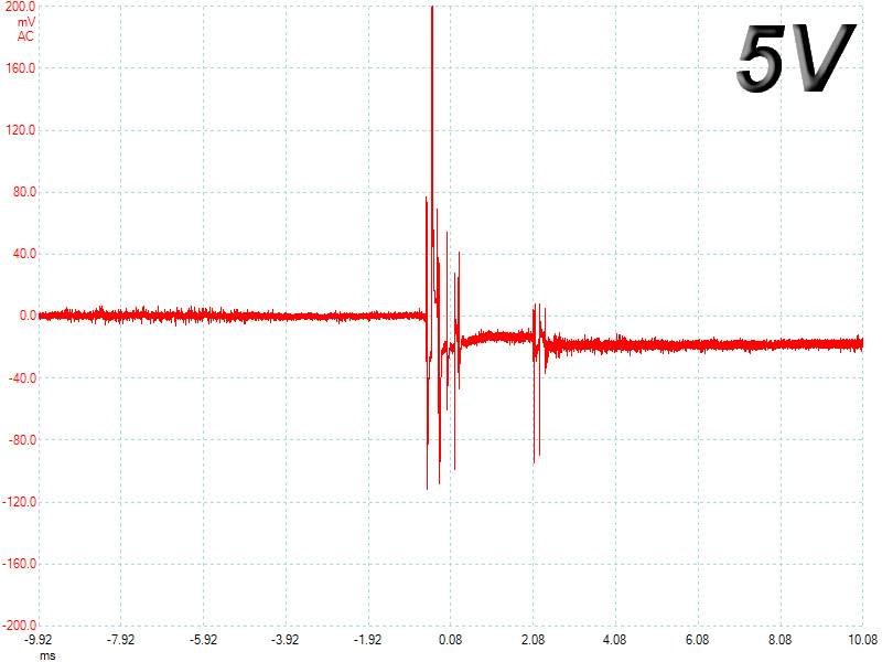
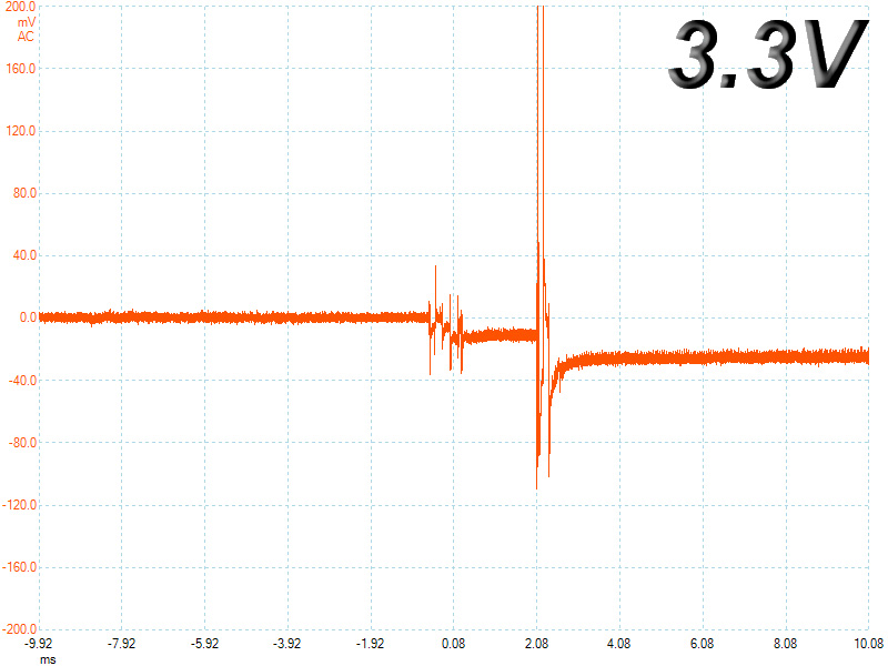
In these tests we monitor the response of the PSU in two different scenarios. First a transient load (11A at +12V, 5A at 5V, 6A at 3.3V and 0.5A at 5VSB) is applied for 50 ms to the PSU, while the latter is working at a 20% load state. In the second scenario the PSU, while working with 50% load, is hit by the same transient load. In both tests, we measure the voltage drops that the transient load causes, using our oscilloscope. In any case voltages should remain within the regulation limits specified by the ATX specification. We must stress here, that the above tests are crucial, since they simulate transient loads that a PSU is very likely to handle (e.g. starting of a RAID array, an instant 100% load of CPU/VGAs etc.) We call these tests “Advanced Transient Response Tests” and they are designed to be very tough to master, especially for PSUs with capacities lower than 500W.| Advanced Transient Response 20% | ||||
|---|---|---|---|---|
| Voltage | Before | After | Change | Pass/Fail |
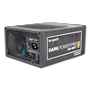
| 12 V | 12.062V | 11.831V | 1.92% | Pass |
| 5 V | 5.020V | 4.907V | 2.25% | Pass |
| 3.3 V | 3.328V | 3.215V | 3.40% | Pass |
| 5VSB | 5.002V | 4.934V | 1.36% | Pass |
| Advanced Transient Response 50% | ||||
|---|---|---|---|---|
| Voltage | Before | After | Change | Pass/Fail |
| 12 V | 12.023V | 11.892V | 1.09% | Pass |
| 5 V | 4.975V | 4.863V | 2.25% | Pass |
| 3.3 V | 3.281V | 3.172V | 3.32% | Pass |
| 5VSB | 4.975V | 4.904V | 1.43% | Pass |
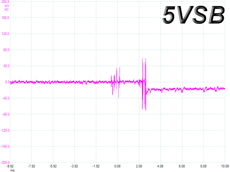
At the first test most likely the PWM operation of the primary switchers is responsible for the huge voltage drop at +12V. Once the load increases the primary switchers operate in FM mode so in the second test the deviation at +12V is way smaller. All in all voltage drops are far from the respective limits and the unit performed fairly well in these tests, taking into account its small capacity which is a handicap here.
Below you will find the oscilloscope screenshots that we took during Advanced Transient Response Testing.
Transient Response at 20% Load
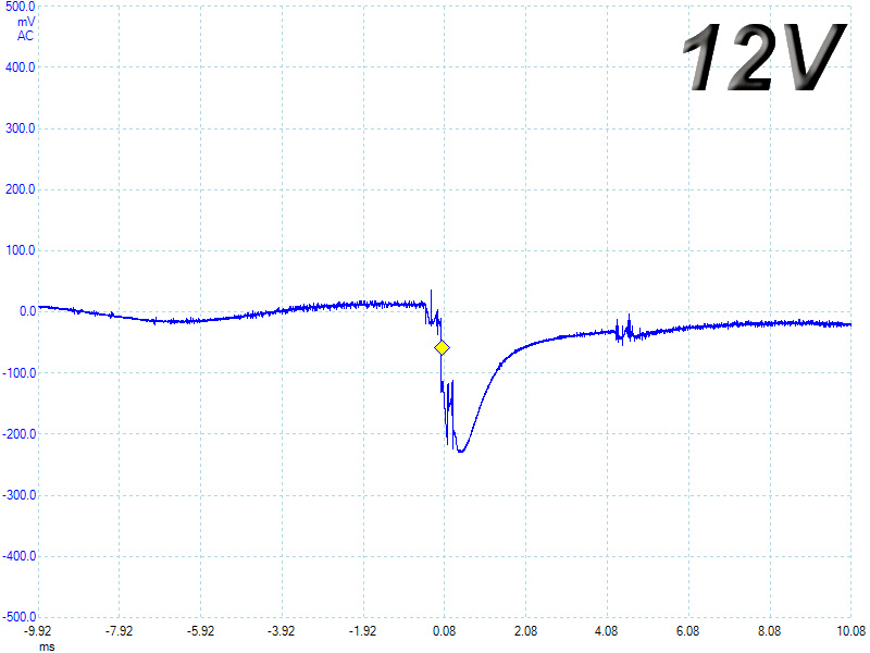
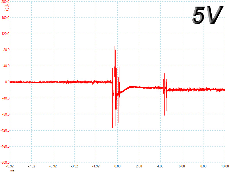
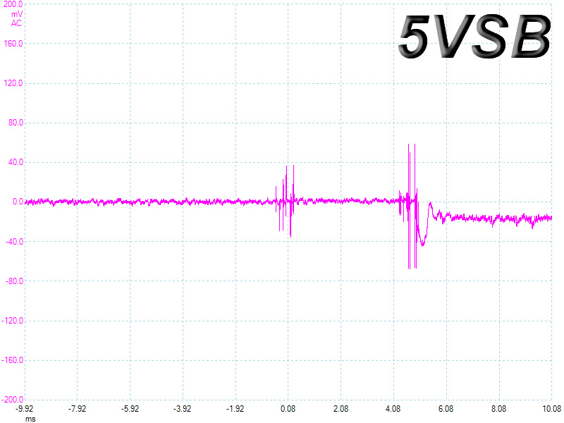
Transient Response at 50% Load
Turn-On Transient Tests
In the next set of tests we measure the response of the PSU in simpler scenarios of transient loads, during the turn on phase of the PSU. In the first test we turn off the PSU, dial 2A load at 5VSB and then switch on the PSU. In the second test, while the PSU is in standby, we dial the maximum load that +12V can handle and we start the PSU. In the last test, while the PSU is completely switched off (we cut off power or switch off the PSU's On/Off switch), we dial the maximum load that +12V can handle and then we switch on the PSU from the loader and we restore power. The ATX specification states that recorded spikes on all rails should not exceed 10% of their nominal values (e.g. +10% for 12V is 13.2V and for 5V is 5.5V).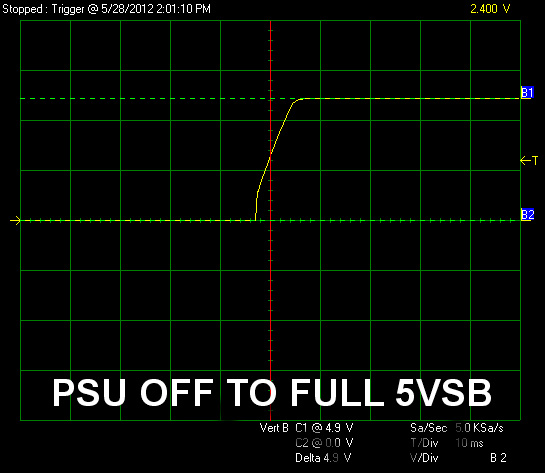
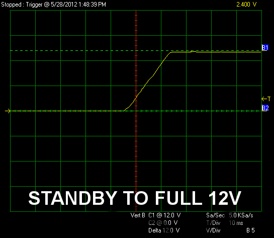
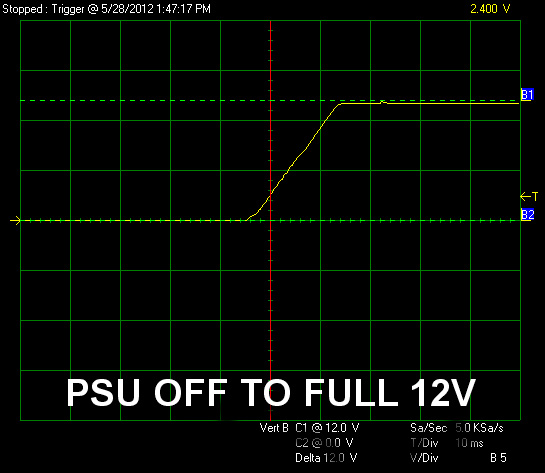
All slopes are smooth without any significant voltage overshoots. Only at +12V we noticed two tiny spikes which however don't exceed even the nominal voltage of this rail. Also the rise time in all cases is within the specified range (0.2-20ms). In general the PSU performed excellent here.
Jun 30th, 2025 18:06 CDT
change timezone
Latest GPU Drivers
New Forum Posts
- The TPU UK Clubhouse (26529)
- Will you buy a RTX 5090? (580)
- Do you use Linux? (663)
- Can you guess Which game it is? (194)
- Help me choose the right PSU , Cooler Master vs Seasonic (53)
- HOW TO ADD NVMe M.2 SSD SUPPORT TO OLD MOTHERBOARDS WITH AWARD-Phoenix LEGACY SUPPORT? (2)
- Whats a fair asking price - MSI 4070 Super (4)
- HTPC Power Consumption Discussion, Upgrade vs Migration (18)
- RX 9000 series GPU Owners Club (1103)
- Rare GPUs / Unreleased GPUs (2111)
Popular Reviews
- Sapphire Radeon RX 9070 XT Nitro+ Review - Beating NVIDIA
- ASUS ROG Crosshair X870E Extreme Review
- Sapphire Radeon RX 9060 XT Pulse OC 16 GB Review - Samsung Memory Tested
- Lexar NQ780 4 TB Review
- AVerMedia CamStream 4K Review
- ASRock Phantom Gaming Z890 Riptide Wi-Fi Review
- AMD Ryzen 7 9800X3D Review - The Best Gaming Processor
- Upcoming Hardware Launches 2025 (Updated May 2025)
- Intel Core Ultra 7 265K Review
- NVIDIA GeForce RTX 5060 8 GB Review
TPU on YouTube
Controversial News Posts
- Intel's Core Ultra 7 265K and 265KF CPUs Dip Below $250 (288)
- NVIDIA Grabs Market Share, AMD Loses Ground, and Intel Disappears in Latest dGPU Update (204)
- Some Intel Nova Lake CPUs Rumored to Challenge AMD's 3D V-Cache in Desktop Gaming (140)
- Microsoft Partners with AMD for Next-gen Xbox Hardware (105)
- NVIDIA Launches GeForce RTX 5050 for Desktops and Laptops, Starts at $249 (104)
- Intel "Nova Lake‑S" Series: Seven SKUs, Up to 52 Cores and 150 W TDP (100)
- NVIDIA GeForce RTX 5080 SUPER Could Feature 24 GB Memory, Increased Power Limits (89)
- Reviewers Bemused by Restrictive Sampling of RX 9060 XT 8 GB Cards (88)