 3
3
Be Quiet! Pure Power CM L8 730 W Review
Voltage Regulation & Efficiency »A Look Inside
Before reading this page we strongly suggest to take a look at this article, which will help you understand the internal components of a PSU much better.
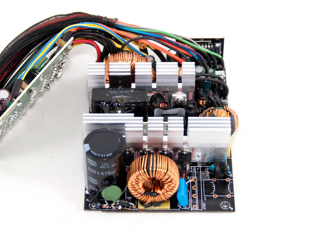
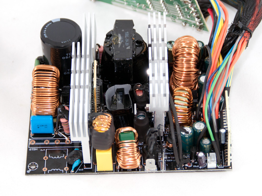
For the Pure Power CM L8 series Be Quiet turned to HEC/Compucase instead of FSP, their favorite OEM. In order to give you a better view of the main PCB we removed a coil from the transient filter and the bridge rectifier along with its heatsink. Here we should stress that we found two convenient terminal crimps which connect the power cables from the small PCB behind the AC receptacle with the main PCB. These crimps permit an effortless disassembly and we wish all manufacturers adopted their use.
Right behind the AC receptacle there is a small PCB with some components of the transient filtering stage, namely one X and two Y caps. On this PCB we also find an On/Off switch. In the main PCB we find more transient parts, three chokes, an MOV, one X and two Y caps. Thankfully HEC utilizes MOVs in their designs, contrary to FSP. To be frank we never understood why FSP hates MOVs so much, since they rarely use them in their PSUs.
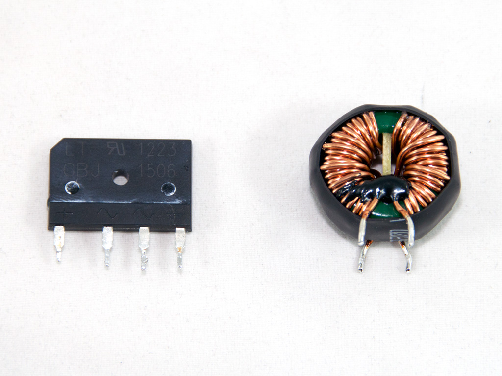
As we move forward and follow the current's path along the main PCB we find the bridge rectifier, a GBJ 1506, which is cooled by a dedicated heatsink. A little theory here: the role of the bridge rectifier is to fully rectify the AC input power, so with 230VAC input we get 230*0.9=207 VDC right after the bridge and double the ripple frequency compared to the AC mains frequency (2*50 Hz in our case).
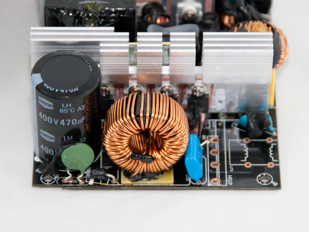
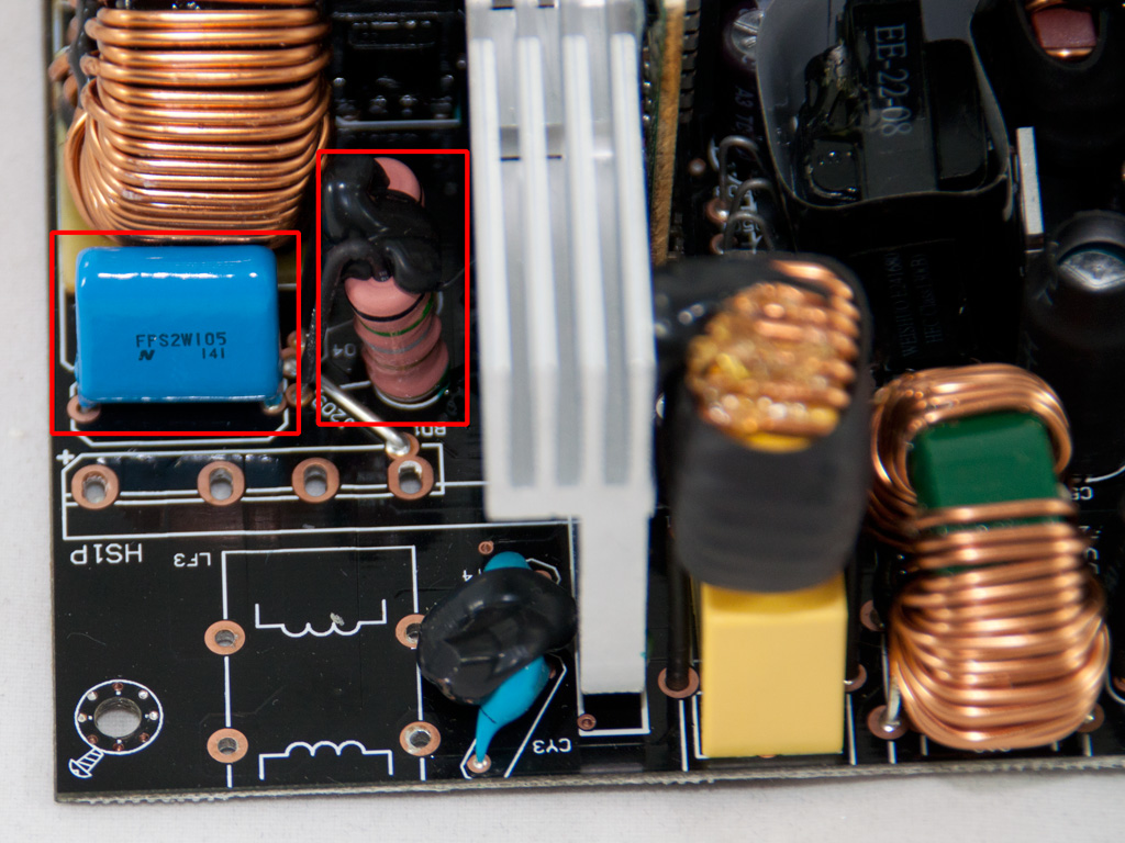

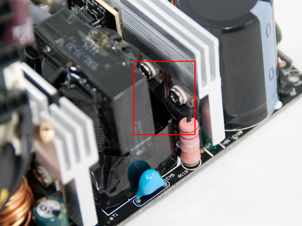
Right after the bridge, as usual, we find the PFC input capacitor, an FPS2W105 X cap which filters the high frequency ripple of the bridge rectifier output. Right next to it there are the current sense resistors, used by the PFC controller. The APFC mosfets are three SPP20N60C3 and the hold up capacitor is provided by Teapo (400V, 470μF, 85°C). Here we should note that although 420/450V caps are preferred at this stage, since the APFC stage provides a 380V DC-bus, many manufacturers choose to use 400V ones since they are cheaper. However in order to use a 400V hold up cap there must be a tight tolerance in the feedback/reference voltage of the PFC controller to ensure that in any case the cap will not take voltage beyond its rating. Our opinion is that a 420/450V cap would be a safer choice here, even if this would led to slightly increased manufacturing cost.
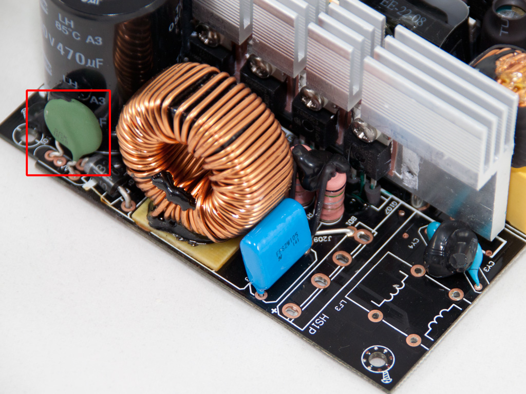
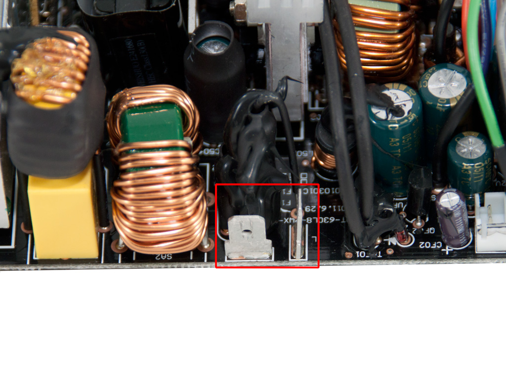
Right in front of the hold up cap we find the thermistor that provides protection against large inrush currents. Of course since the PSU is only 80 PLUS Bronze certified there is no relay to bypass it, once the PSU's start up sequence finishes and the APFC cap is charged.
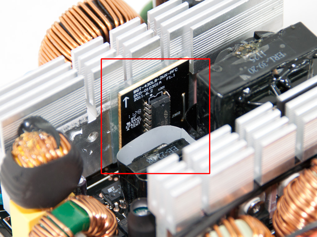
As main switches/choppers two SPP20N60C3 mosfets are used. Right next to them resides a vertical daughter-board which houses the combo PFC/PWM controller, the omnipresent CM6800TX.
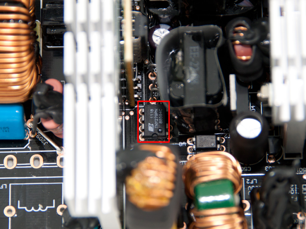
The standby PWM controller is a TNY279PN IC, made by Power Integrations. This IC incorporates a 700V power MOSFET to handle the 5VSB output.
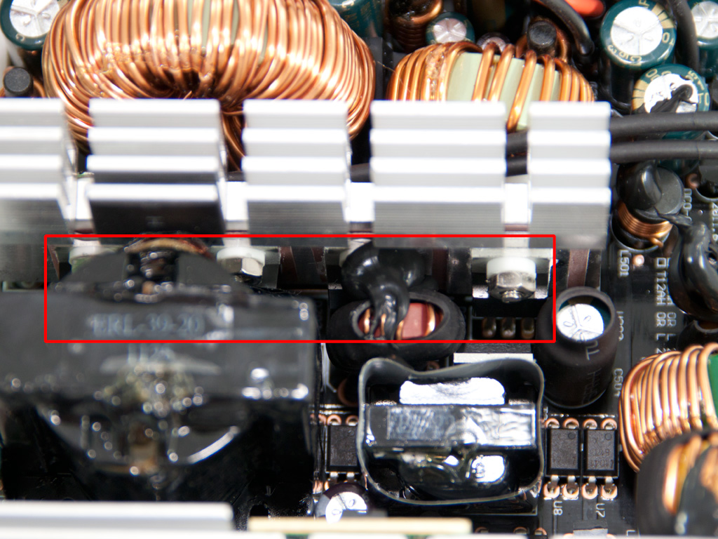

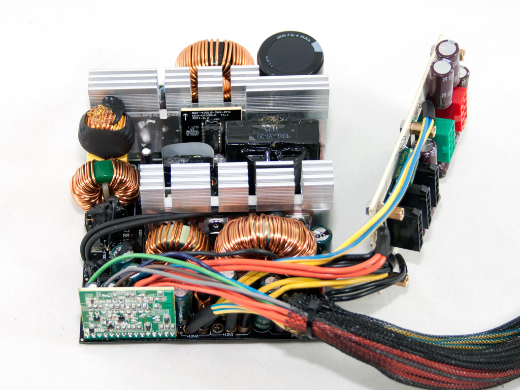
In the secondary side only passive components (SBRs) are used, The +12V rail is regulated by four 30A40CT SBRs, the 5V by two 40U60CT and the 3.3V rail by two 30A40CT. The presence of two coils in this case means that group regulation is used, so the bigger coil is shared by 12V and 5V and the smaller one is used for the rectification/filtering of 3.3V. For sure we couldn't demand expensive DC-DC converters here but we would like to see at least independent regulation which would offer much better performance in crossload tests.
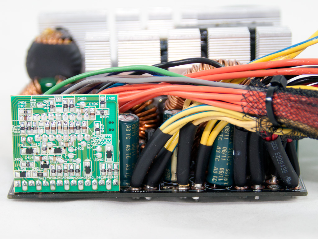
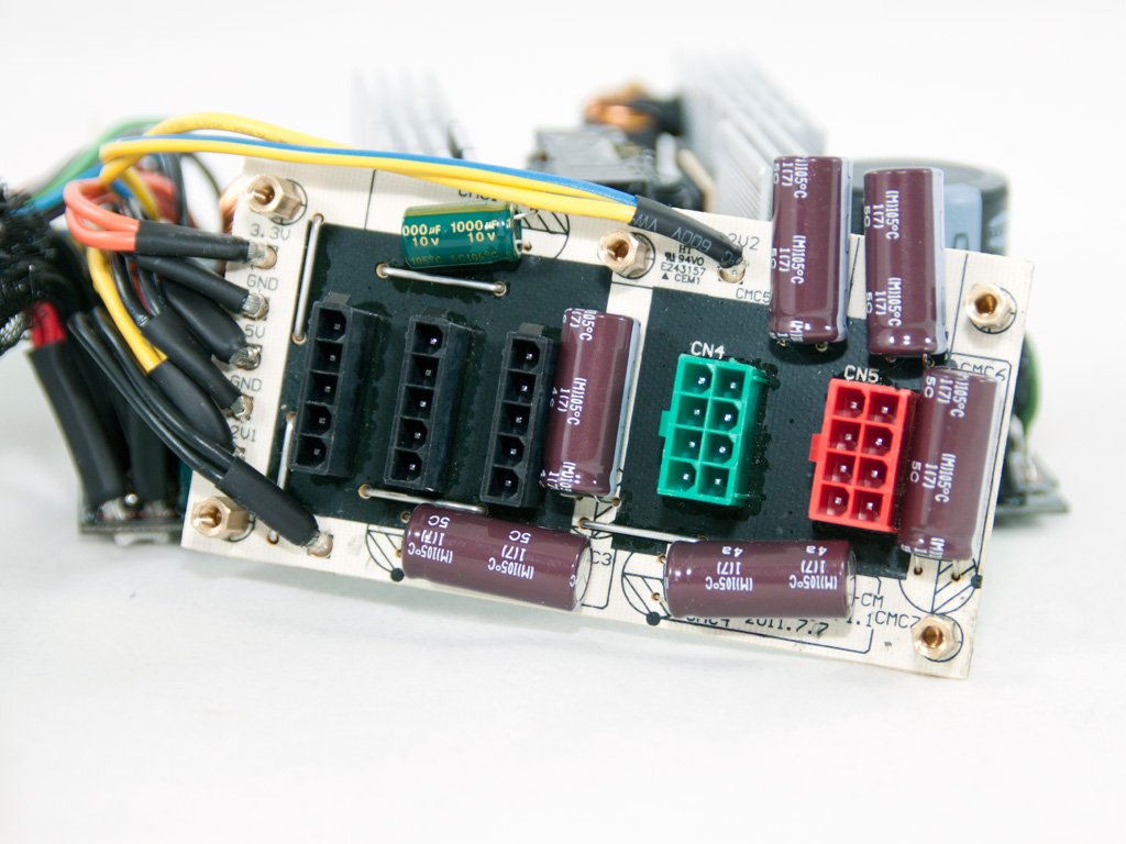
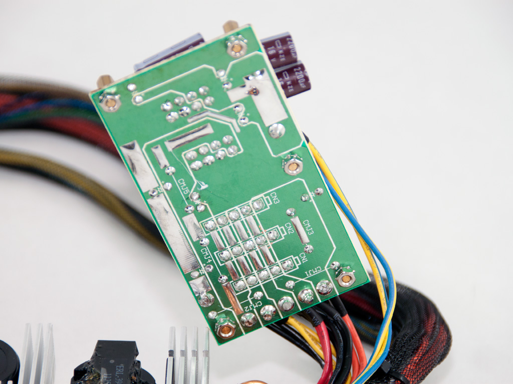
All capacitors in the secondary are provided by Teapo and rated at 105°C. On the modular PCB six Nippon Chemi-Con caps and a small Teapo are used for further ripple filtering. As it seems the main PCB didn't have enough space for all required caps so the modular PCB had to accommodate some of them.
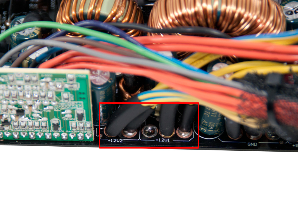
The PCB supports two +12V rails.
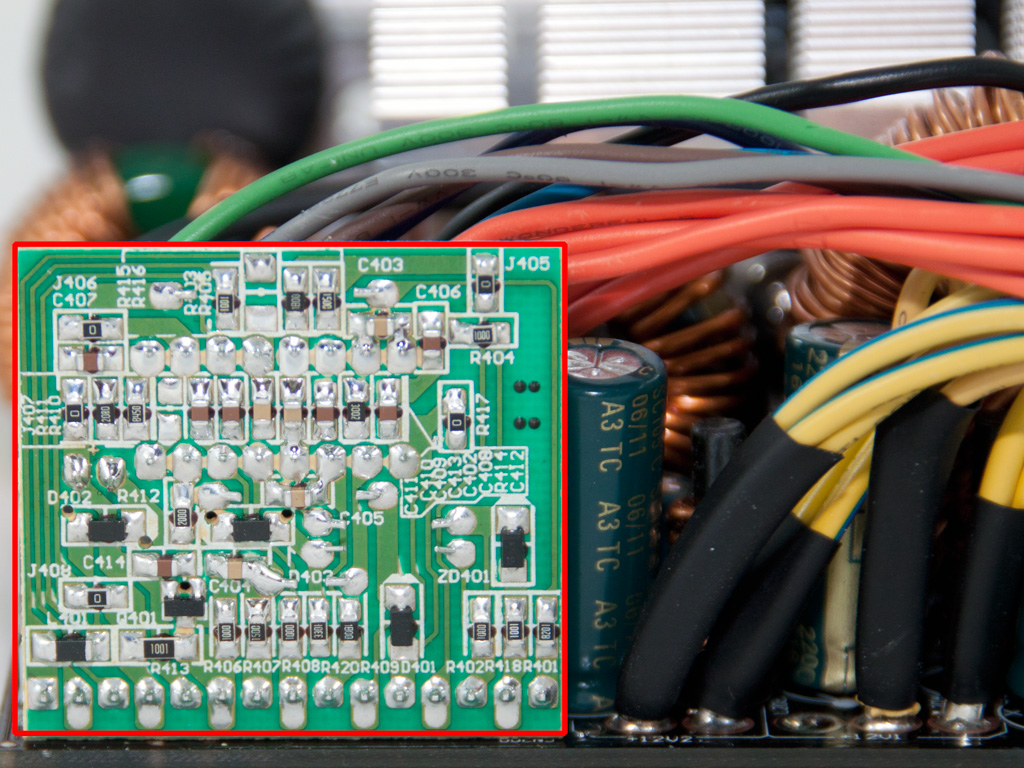
In the above daughter-board the protections IC is soldered, a Weltrend 7527. This IC supports OCP for two +12V rails and all other protections besides OTP (Over Temperature Protection). As it seems this protection is implemented using an extra circuit and the trigger signal is transferred to the 7527 through pin 9 (extra protection sense input).
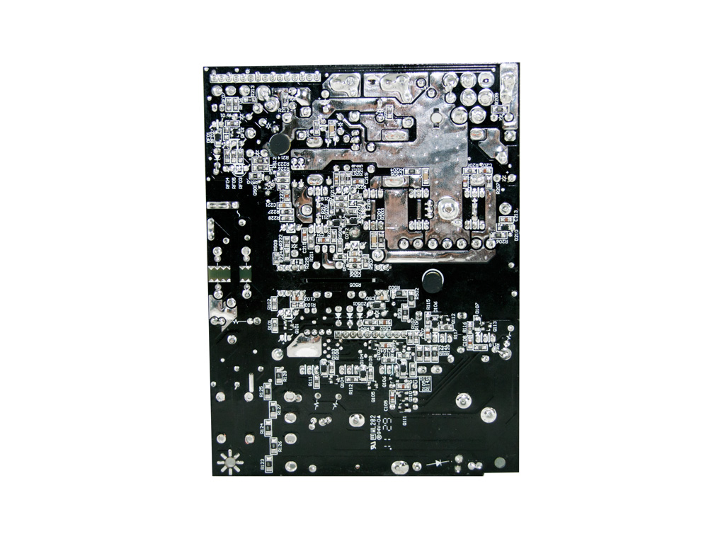
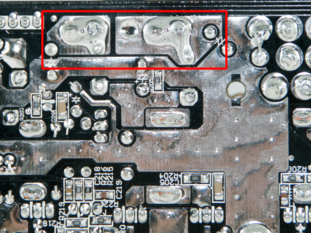
The solder side of the main PCB features very clean and well made solder joints. This time HEC/Compucase did a really fine soldering job. The same applies to the modular PCB, too.
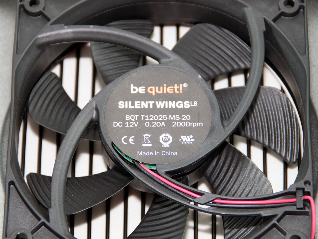
The cooling fan is provided by Be Quiet of course and utilizes special designed blades that increase airflow and decrease output noise levels at the same time. Its model number is BQT T12025-MS-20 (12V, 0.2A, 2000 RPM, sleeve bearing, 29.6 dBA max).
Jul 10th, 2025 02:37 CDT
change timezone
Latest GPU Drivers
New Forum Posts
- Do you still use Antivirus software on your latest hardware? (75)
- Screen burn-in (21)
- TPU's Nostalgic Hardware Club (20493)
- 3DMARK "LEGENDARY" (326)
- Post Your TIMESPY, PCMARK10 & FIRESTRIKE SCORES! (2019) (321)
- 5070ti overclock...what are your settings? (47)
- 'NVIDIA App' not usable offline? (1)
- G-Sync Not Working in Borderless / Window Mode - Windows 11 (5)
- [GPU-Z Test Build] New Kernel Driver, Everyone: Please Test (78)
- Friend's monitor randomly loses signal (3)
Popular Reviews
- NZXT N9 X870E Review
- NVIDIA GeForce RTX 5050 8 GB Review
- Fractal Design Epoch RGB TG Review
- Corsair FRAME 5000D RS Review
- Fractal Design Scape Review - Debut Done Right
- AMD Ryzen 7 9800X3D Review - The Best Gaming Processor
- Sapphire Radeon RX 9060 XT Pulse OC 16 GB Review - An Excellent Choice
- Upcoming Hardware Launches 2025 (Updated May 2025)
- Sapphire Radeon RX 9070 XT Nitro+ Review - Beating NVIDIA
- PowerColor ALPHYN AM10 Review
TPU on YouTube
Controversial News Posts
- Intel's Core Ultra 7 265K and 265KF CPUs Dip Below $250 (288)
- Some Intel Nova Lake CPUs Rumored to Challenge AMD's 3D V-Cache in Desktop Gaming (140)
- NVIDIA Launches GeForce RTX 5050 for Desktops and Laptops, Starts at $249 (117)
- AMD Radeon RX 9070 XT Gains 9% Performance at 1440p with Latest Driver, Beats RTX 5070 Ti (116)
- NVIDIA GeForce RTX 5080 SUPER Could Feature 24 GB Memory, Increased Power Limits (115)
- Microsoft Partners with AMD for Next-gen Xbox Hardware (105)
- Intel "Nova Lake‑S" Series: Seven SKUs, Up to 52 Cores and 150 W TDP (100)
- NVIDIA DLSS Transformer Cuts VRAM Usage by 20% (97)