 4
4
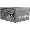
Cooler Master V Series 650 W Review
Load Regulation, Hold-up Time & Inrush Current »A Look Inside & Component Analysis
Before reading this page, we strongly suggest a look at this article, which will help you understand the internal components of a PSU much better. Our main tool for the disassembly of the PSU is a Thermaltronics TMT-9000S soldering and rework station. It is of extreme quality and is equipped with a matching de-soldering gun. With such equipment in hand, breaking apart every PSU is like a walk in the park!| Corsair V650 Parts Description | |
|---|---|
| Primary Side | |
| Transient Filter | 4x Y caps, 3x X caps, 2x CM chokes, 1x CM02X 1x MOV |
| Bridge Rectifier(s) | 1x |
| Inrush Current Protection | NTC Thermistor & Relay |
| APFC Mosfets | 2x Infineon IPP50R280CE (550V, 8.2A @ 100°C, 0.28 mΩ) |
| APFC Boost Diode | 1x STTH12R06D (600V, 12A @ 50°C) |
| Hold-up Cap(s) | 1x Rubycon (420V, 470 uF, 105°C, MXG series, 3000h @ 105°C) |
| Main Switchers | 4x Infineon IPP50R280CE (550V, 8.2A @ 100°C, 0.28 mΩ) |
| APFC Controller | Champion CM6502 - CM03X |
| Switching Controller | Champion CM6901 |
| Topology | Primary side: Full-Bridge Secondary side: Synchronous Rectification & DC-DC converters |
| Secondary Side | |
| +12V | 4x Infineon IPP023N04N G (40V, 90A @ 100°C, 2.3 mΩ) |
| 5V & 3.3V | DC-DC Converters: 4x BSC050NE2LS FETs (30V, 48A @ 100°C, 6.9mΩ @ 125°C) PWM Controllers: 2x APW7073 |
| Filtering Capacitors | Electrolytics: Nippon Chemi-Con (105°C, KY, KZE), United Chemi-Con (105°C, LXZ), Suncon (105°C), Rubycon (105°C) Polymers: Unicon (TW) |
| Supervisor IC | SITI PS223 (OVP, UVP, OCP, SCP, OTP) |
| Fan Model | Silencio A12025-25RB-2IN-F1 (120mm, 12 V, 0.16 A, 2250 RPM, Loop Dynamic Bearing) |
| 5VSB Circuit | |
| Rectifying Diode | PFR10V45CT |
| Standby PWM Controller | Sanken STR-A6069H |
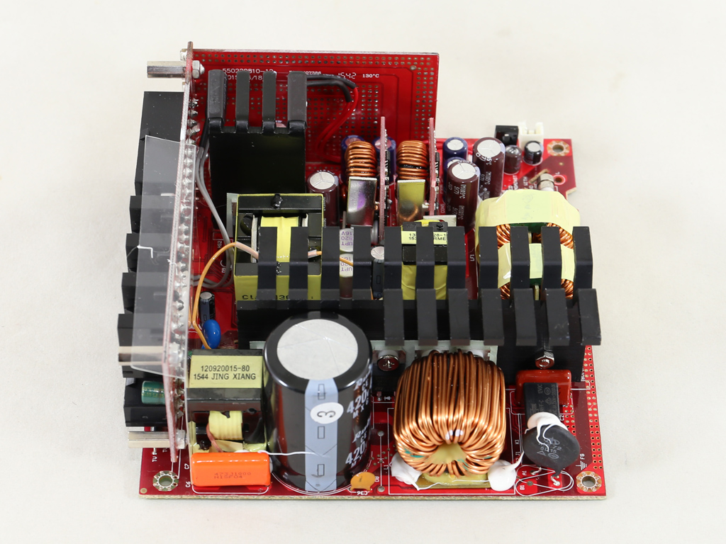
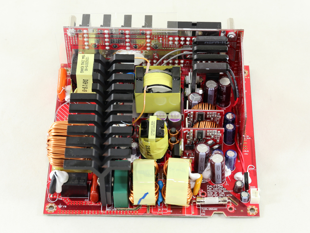
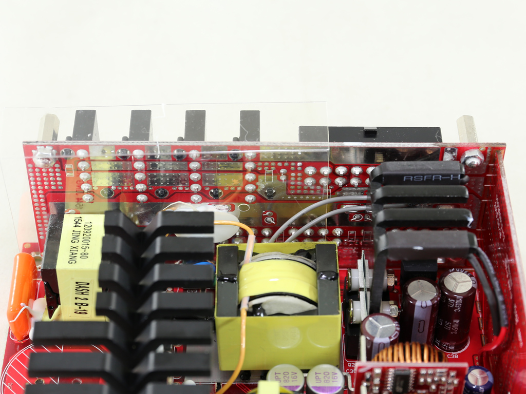
Enhance Electronics manufactures this PSU, and in its primary side is a full-bridge topology and an LLC resonant converter for a major efficiency boost, especially at higher loads. A synchronous design and two VRMs (Voltage Regulation Modules), which generate the minor rails, are used in the secondary side.
The heatsinks aren't large enough, which usually isn't the case in Enhance units. These smaller-than-usual heatsinks allowed us to identify this PSU's components much more readily without having to make excess use of our desoldering station, though. Again, Cooler Master's so-called 3D circuit in the secondary side is actually a vertical daughter board that takes on the role power-transfer cables in other PSUs would. Cooler Master used a very fancy name for this particular board, which is what marketing usually does—it invents fancy names that will help a product stand out from the crowd.
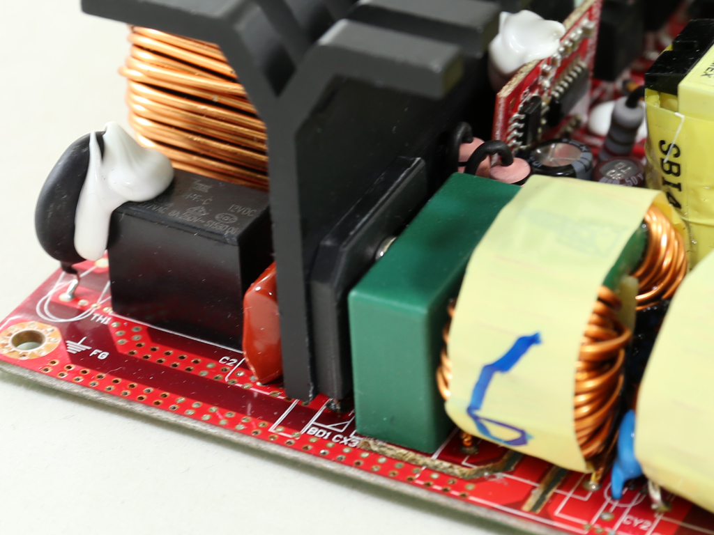
The first part of the transient filter is at the AC receptacle and consists of two Y and two X caps. The rest of the EMI filter is on the mainboard, made up of two Y caps, an X cap, two CM chokes, and an MOV. All in all, the EMI filter is complete.
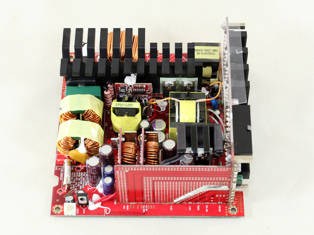
On the mainboard's solder side is a CM02X that blocks the current through the X cap discharge resistor when AC voltage is connected; it also automatically discharges the X cap through the discharge resistor when AC is disconnected. This improves efficiency since X caps tend to keep their charge for quite a long time after AC power has been cut off; as such, bleeding resistors are used for safety. However, some energy is lost to such resistors while the PSU operates, which the CM02X takes care of by isolating the bleeding resistor from the circuit.
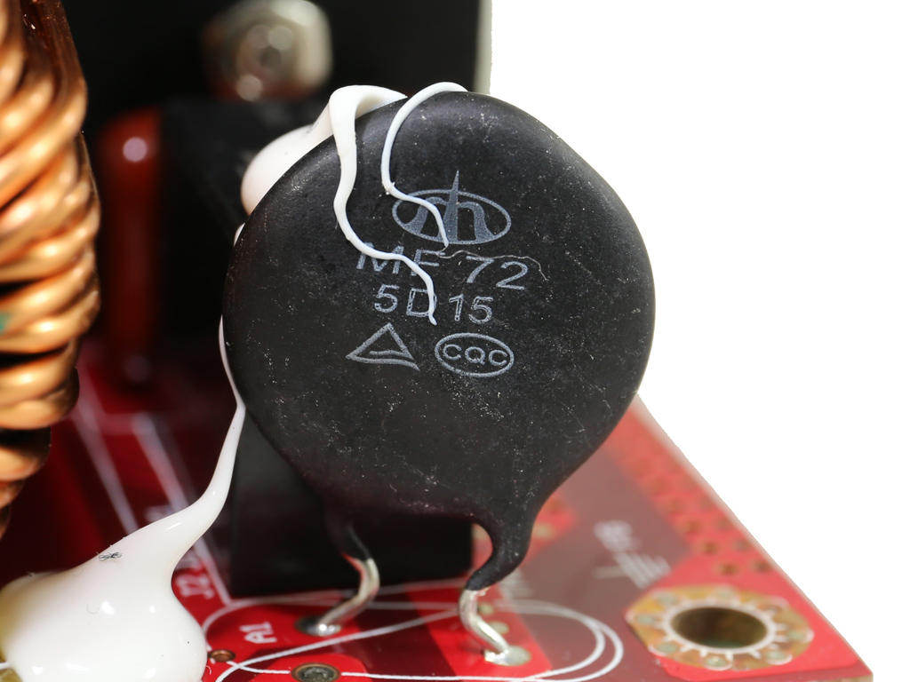
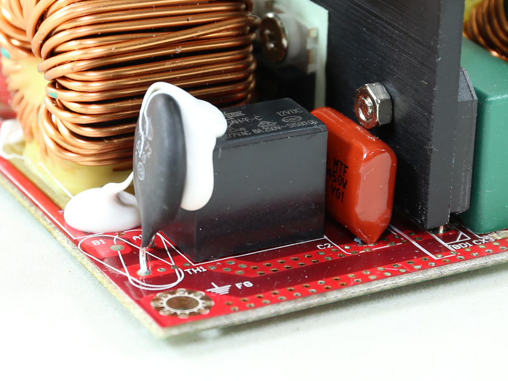
An NTC thermistor and a bypass electromagnetic relay protect this unit against high inrush current. The V550 lacks this relay, so its inrush current is higher since the thermistor doesn't cool down once the PSU starts, making its resistance lower than it should be.
The single bridge rectifier is bolted to the APFC heatsink, and since its markings are hidden, we weren't able to identify it.
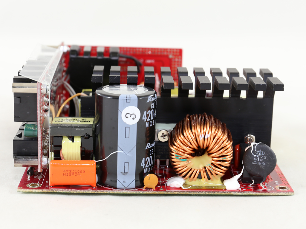
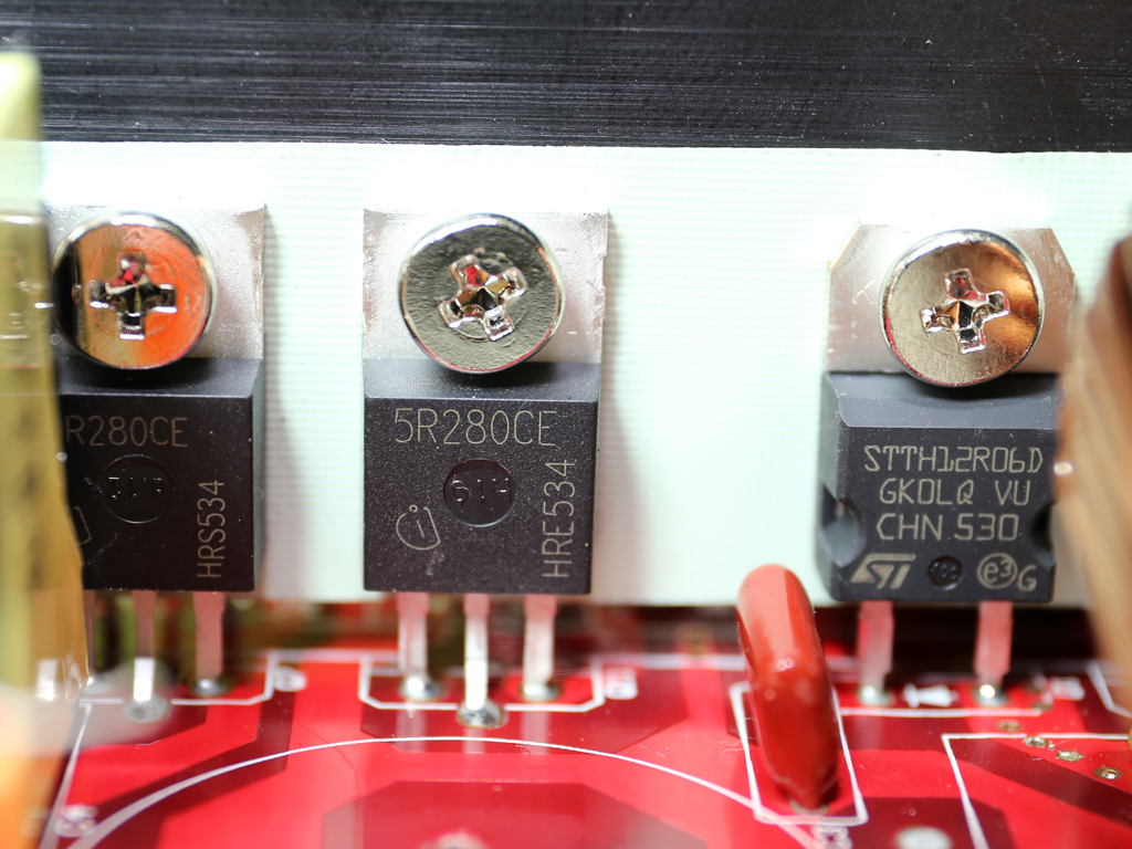
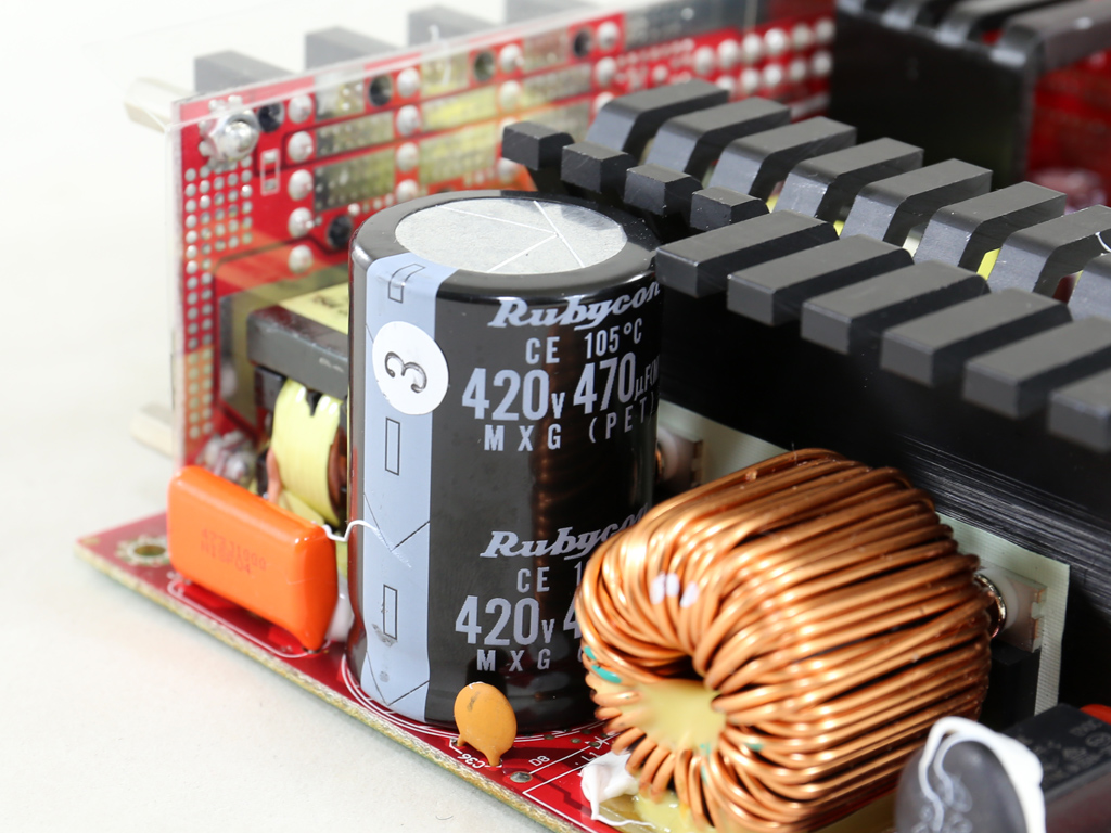
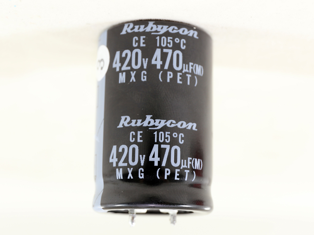
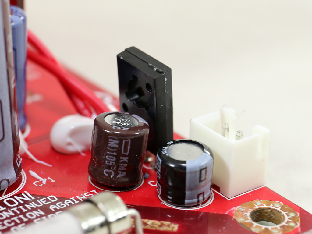
The APFC converter uses two Infineon IPP50R280CE FETs and a single STTH12R06D diode. The bulk cap is by Rubycon (420V, 470 uF, 105°C, MXG series, 3000h @ 105°C), and although it is of high quality, its capacity isn't high enough to allow for a hold-up time over 17ms.
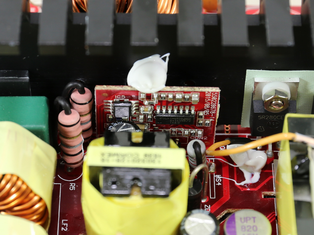
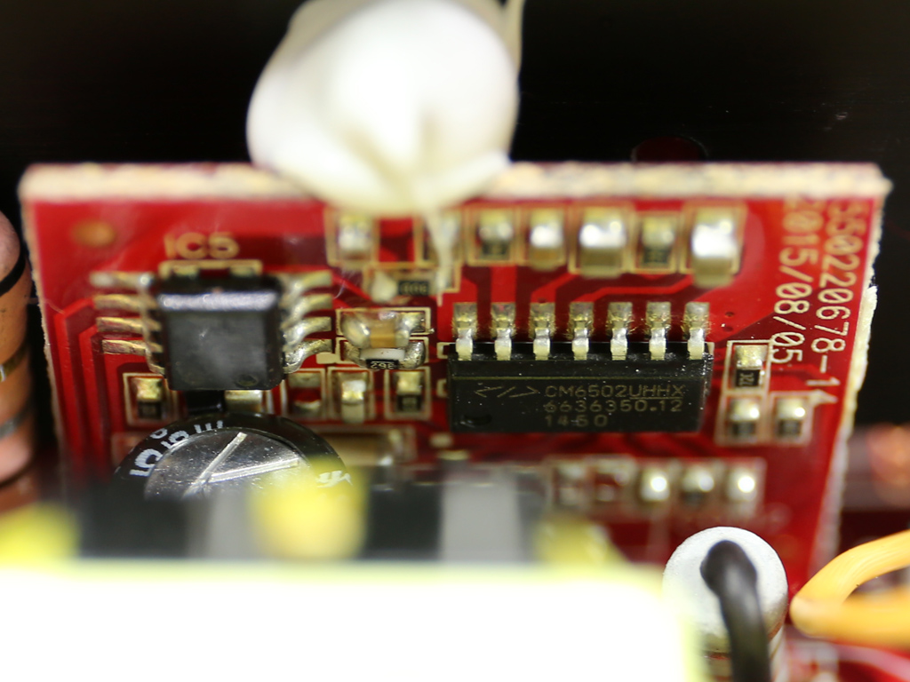
The PFC controller, a Champion CM6500TNX, and a CM03X Green PFC controller that supports it are installed on a small board right next to the APFC heatsink. The CM6500TNX includes an inrush-current-control function that measures how much inrush current is produced during start-up to protect the PSU and the whole system if too high.
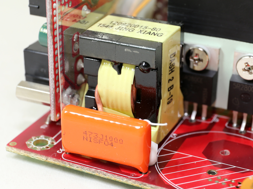
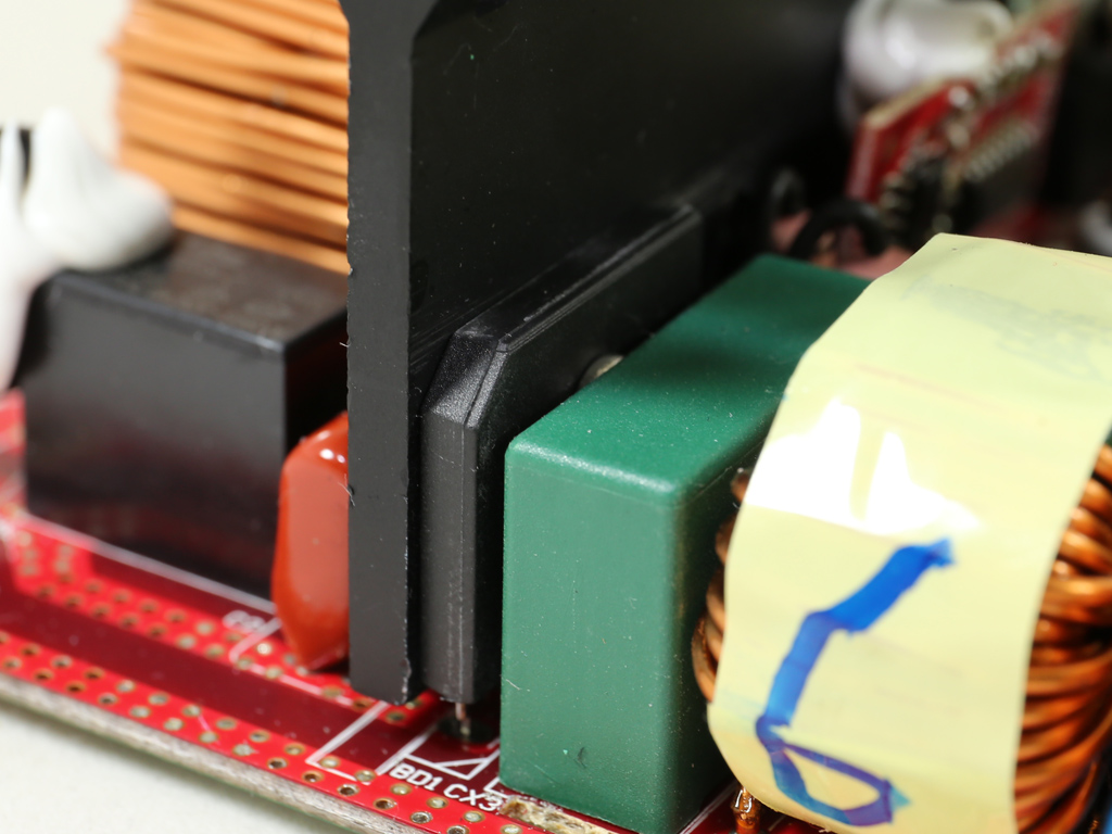
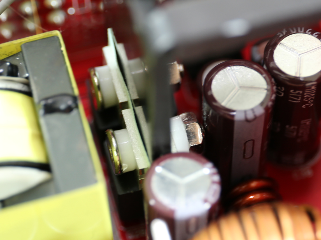
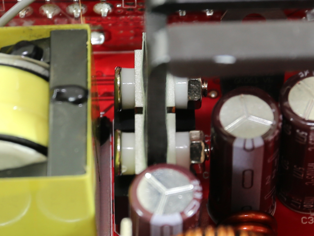
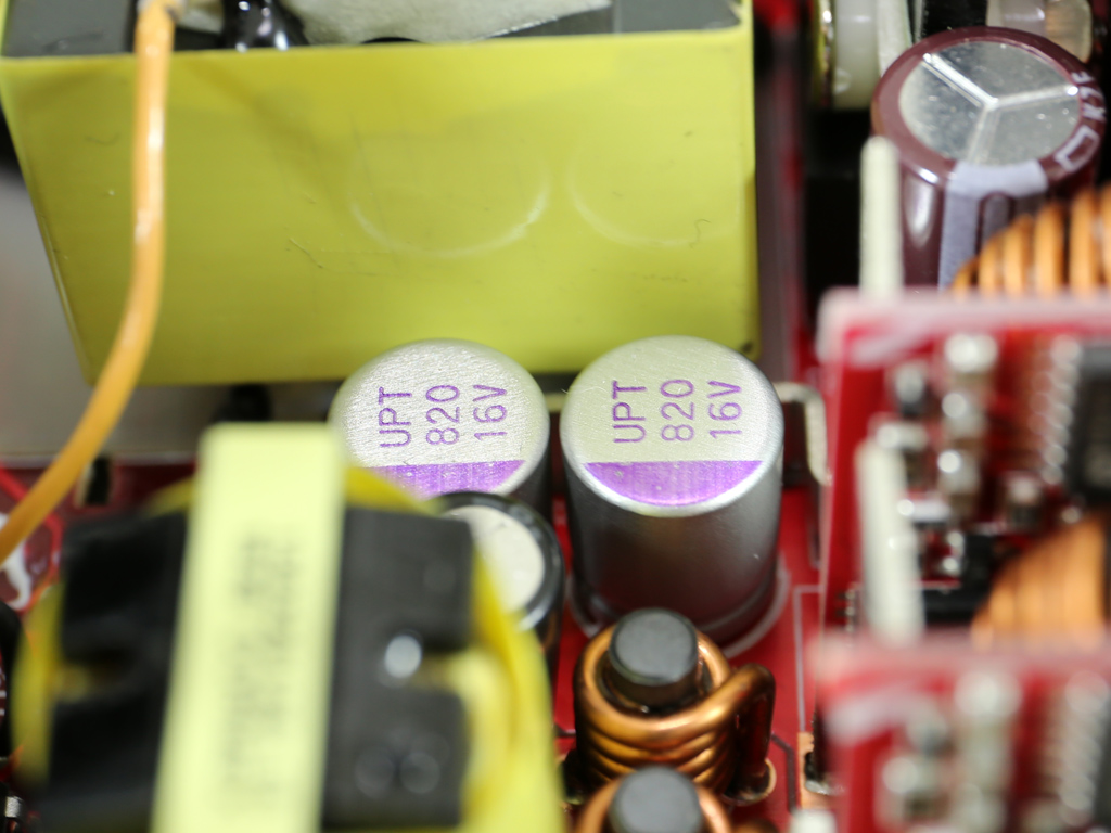
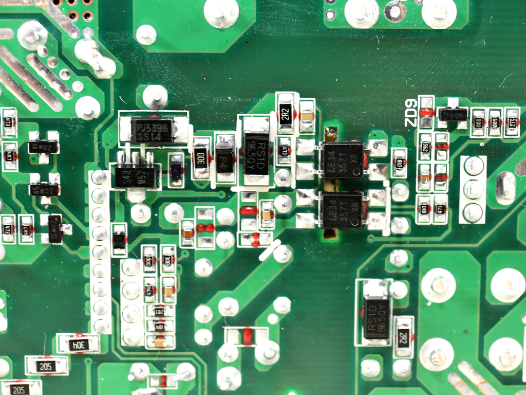
Here are the capacitive and inductive parts of the LLC resonant converter.
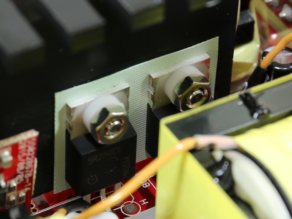
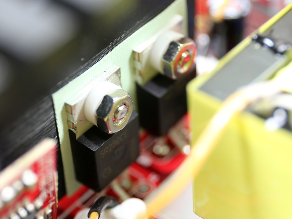
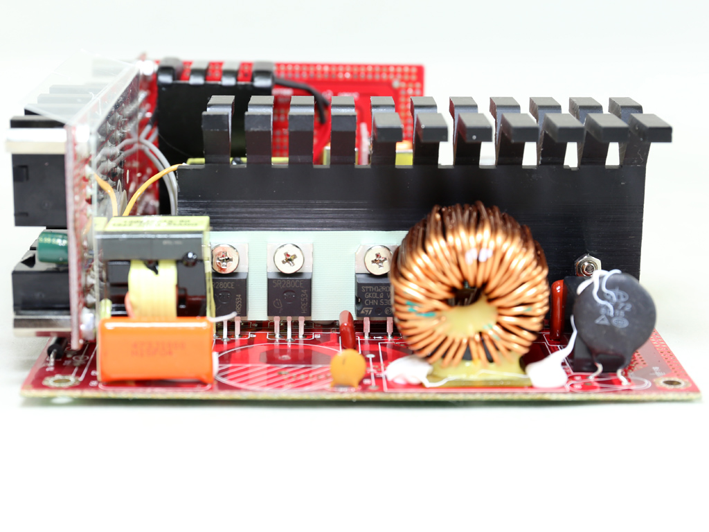
The main switchers are four Infineon IPP50R280CE FETs.
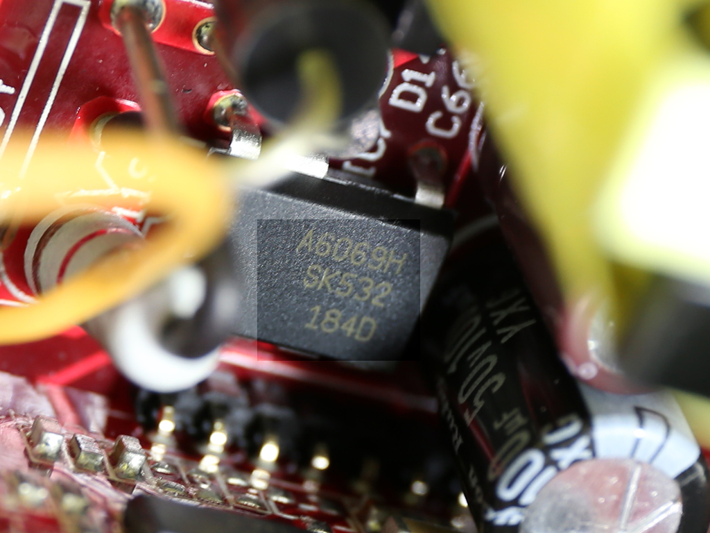
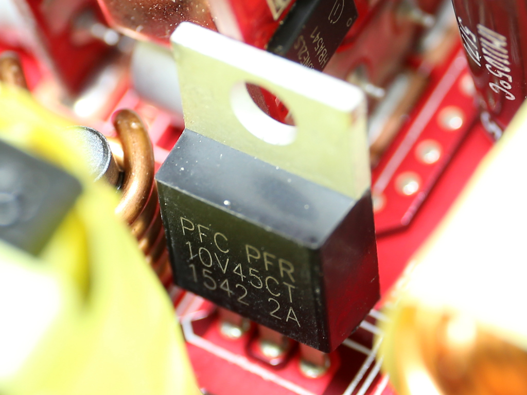
Like in the V550, the standby PWM controller is a Sanken STR-A6069H IC, and the 5VSB rail is rectified by a PFR10V45CT SBR.
The +12V fets in the secondary side, four Infineon IPP041N04N Gs, are installed on a small heatsink with long-enough fins.
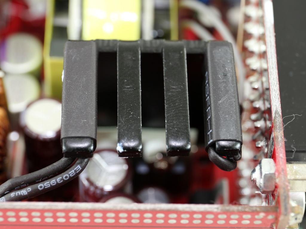
Two thermistors have been attached to the secondary heatsink's fins, which cools down the +12V FETs. These provide temperature information to the fan-control circuit and PS223 IC, which takes care of over-temperature protection.
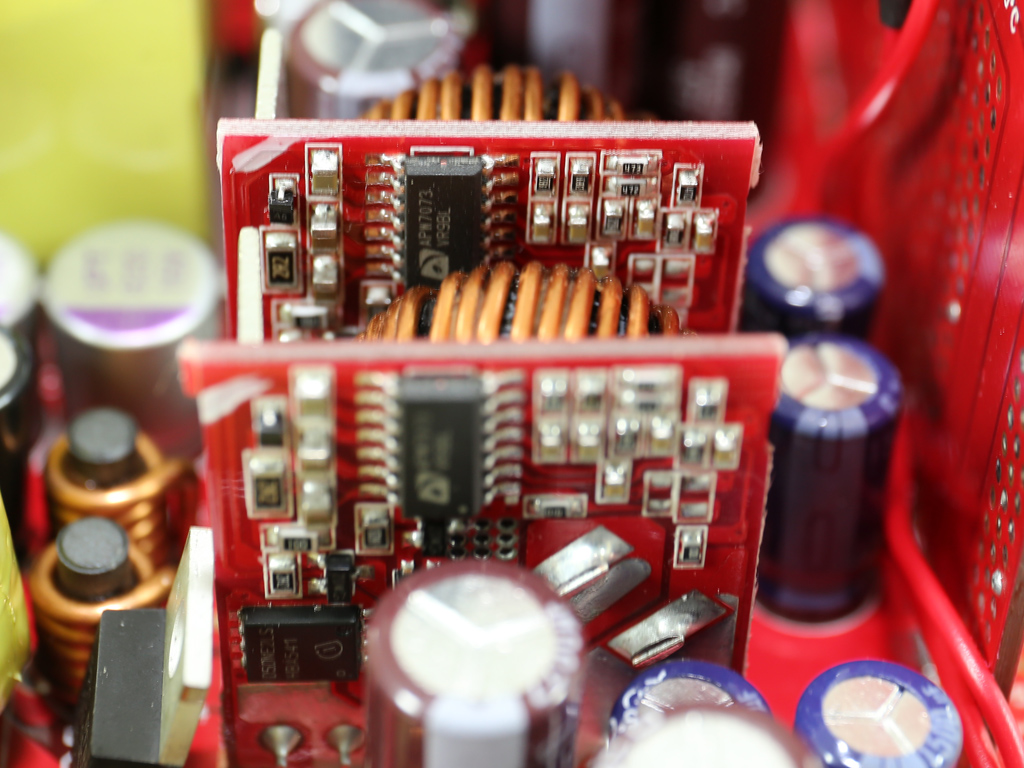
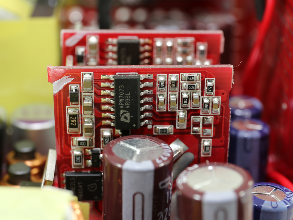
The secondary rails are generated by two small DC-DC converters. Each converter uses an APW7073 PWM controller and two Infineon BSC050NE2LS FETs.
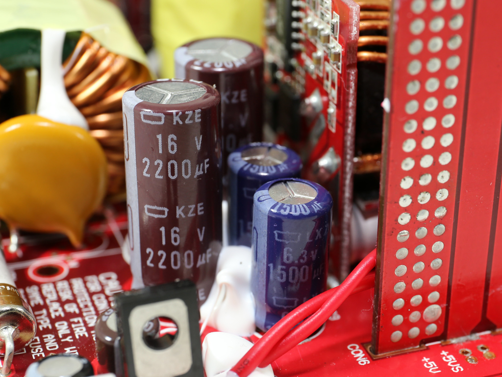

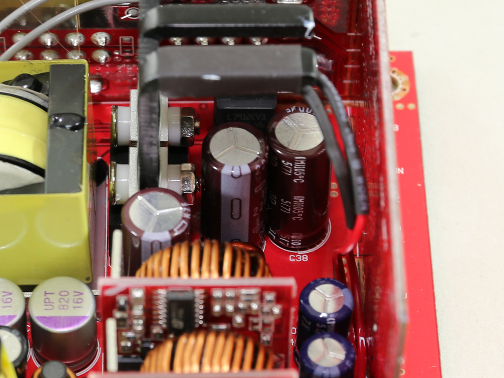
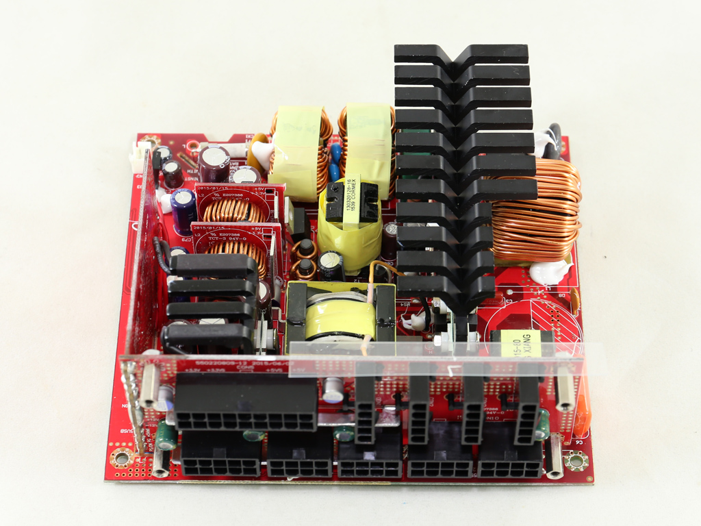
A mixture of Nippon Chemi-Con, United Chemi-Con, and Suncon electrolytic caps filter the +12V rail. We also spotted a single Rubycon electrolytic and two United polymer caps on the mainboard. The older VSM units mostly used Teapo caps, which might be of decent quality, but are no match for similarly spec'd Japanese caps.
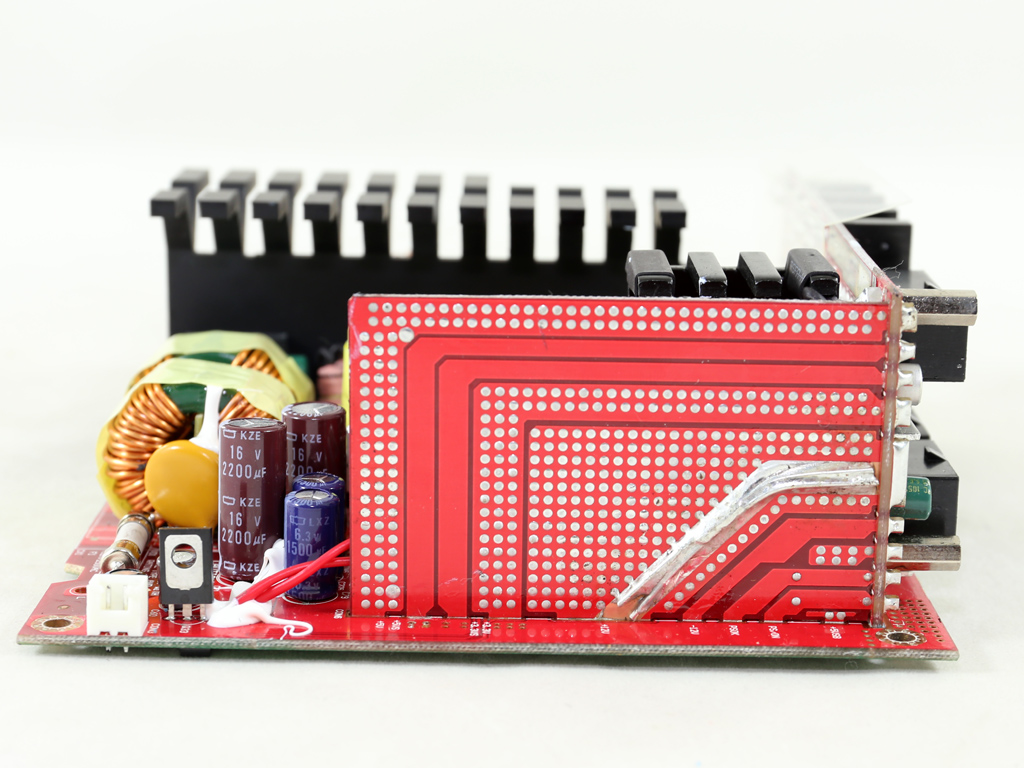
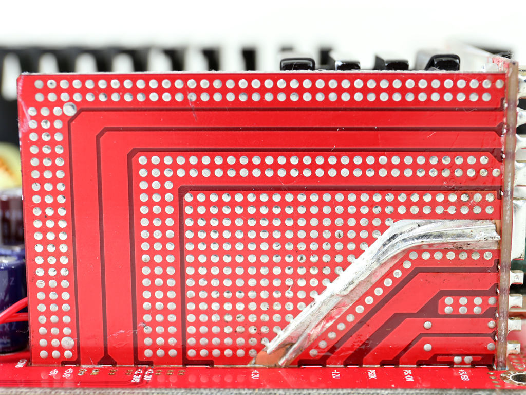
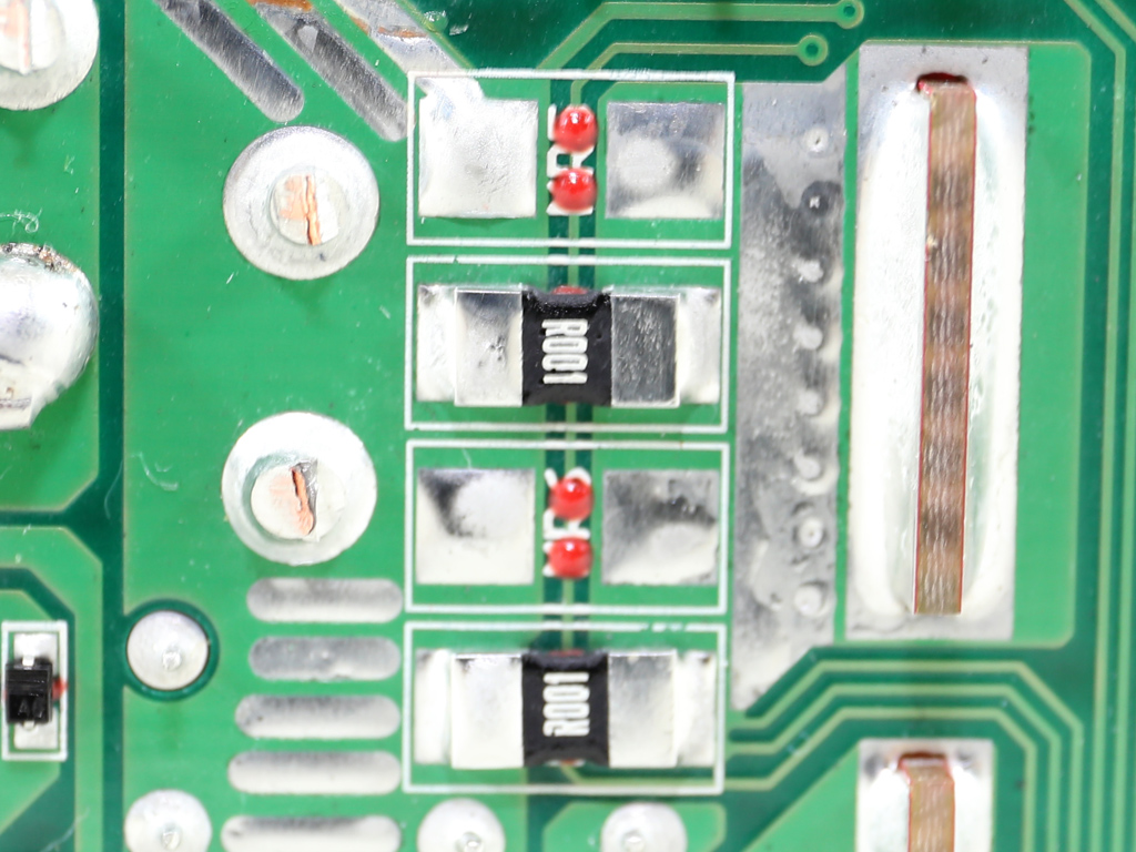
The 3D circuit is just a vertical daughter board that transfers the rails to the modular sockets. This board replaces the power cables that would normally transfer the power from the regulation circuits to the modular panel's sockets, which increases efficiency. The wide PCB traces of this board are shorter and have less impedance. A such, less energy goes to waste. The enhanced trace onto which two copper wires are soldered transfers +12V to the modular board.
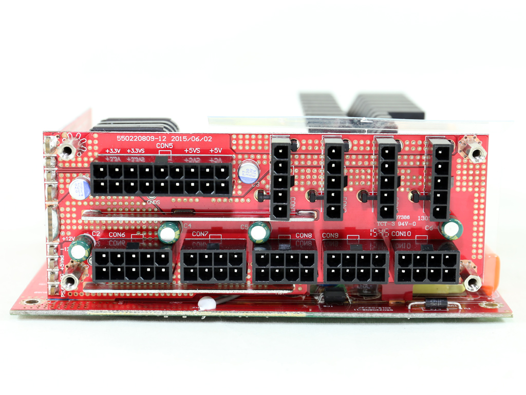

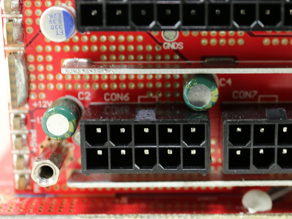
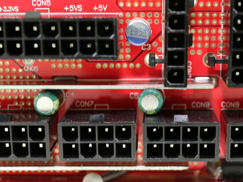
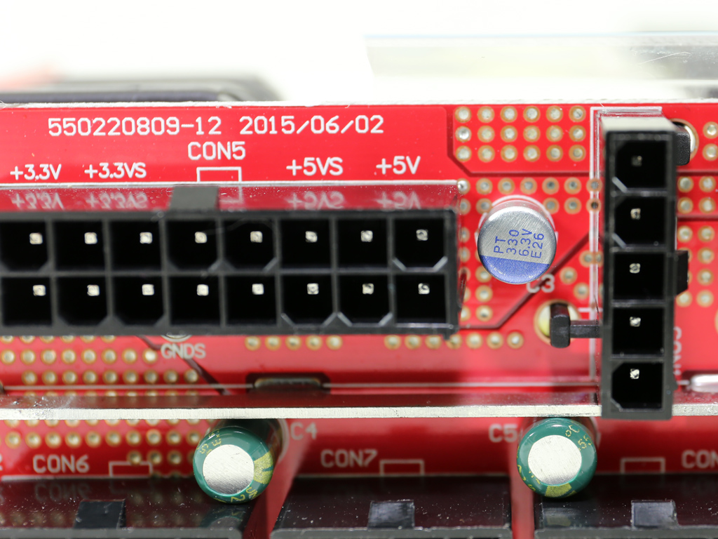
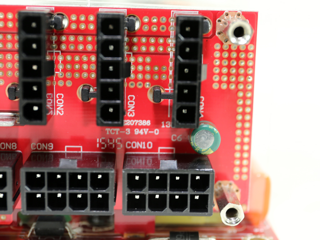
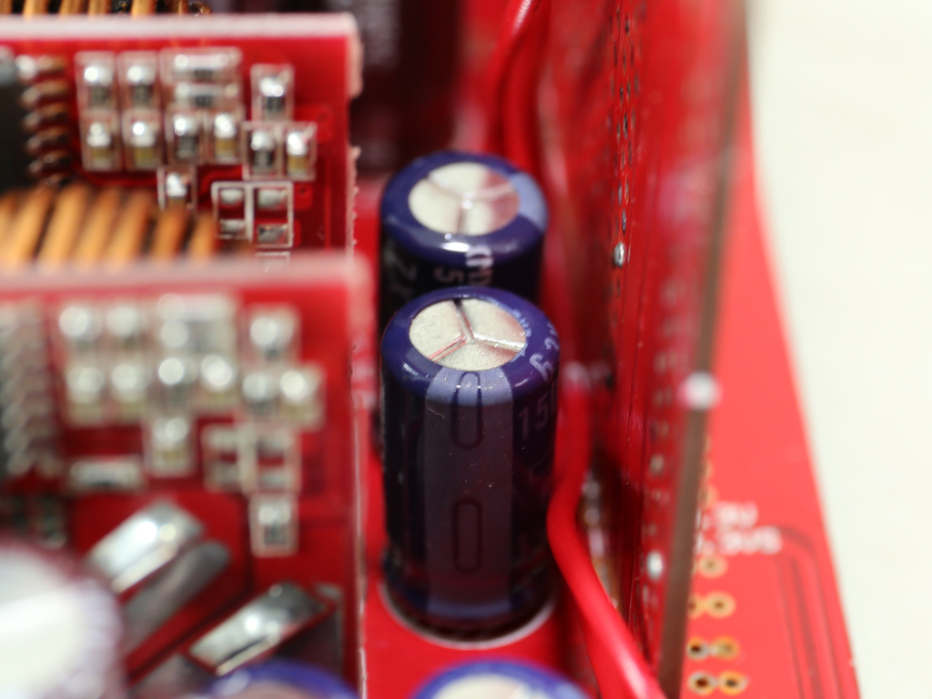
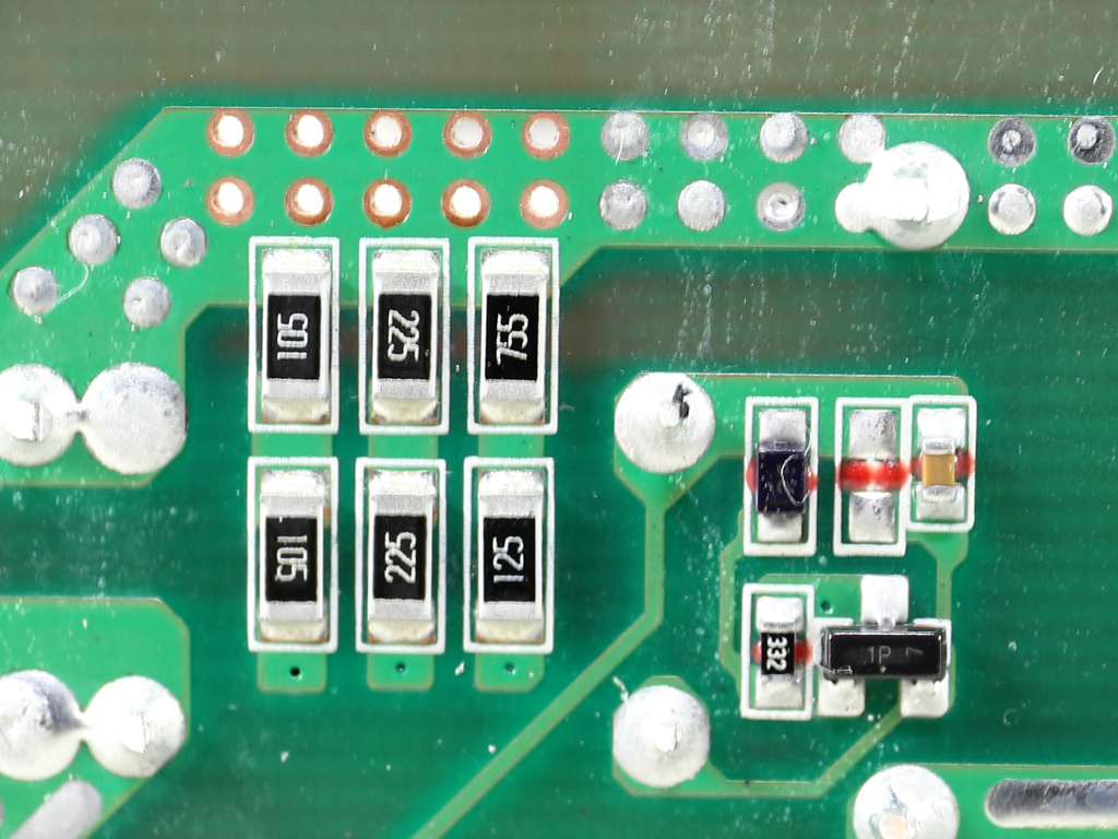
Several United polymer and a number of Suncon electrolytic caps further suppress ripple at the front of the modular PCB.
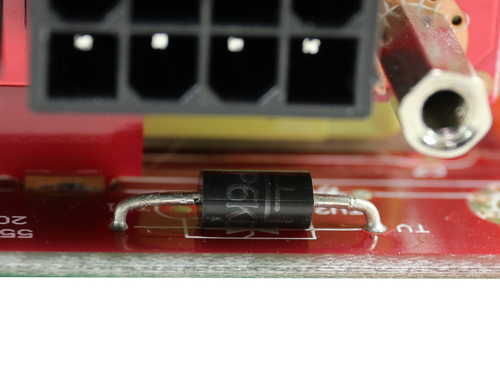
Soldering quality on the secondary side of the modular board looks good.
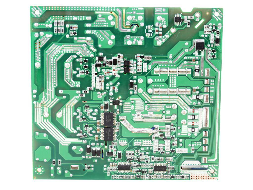
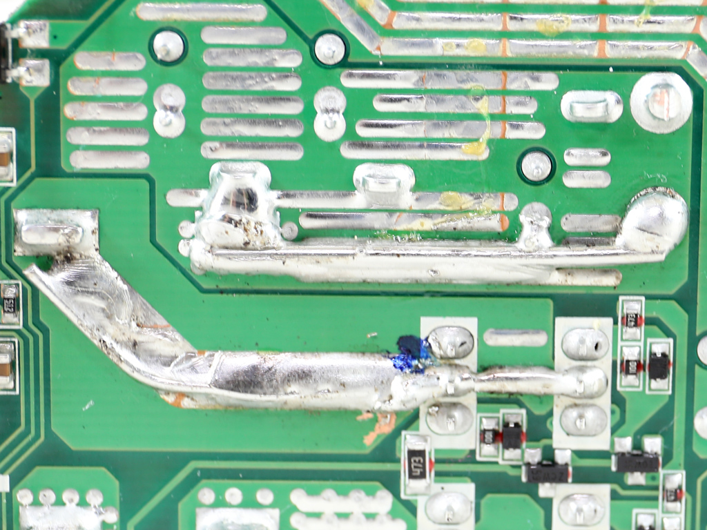
Soldering quality is very good. We only found two ugly PCB traces, enhanced with copper wires that were soldered onto them on this side.
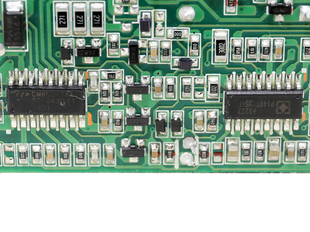
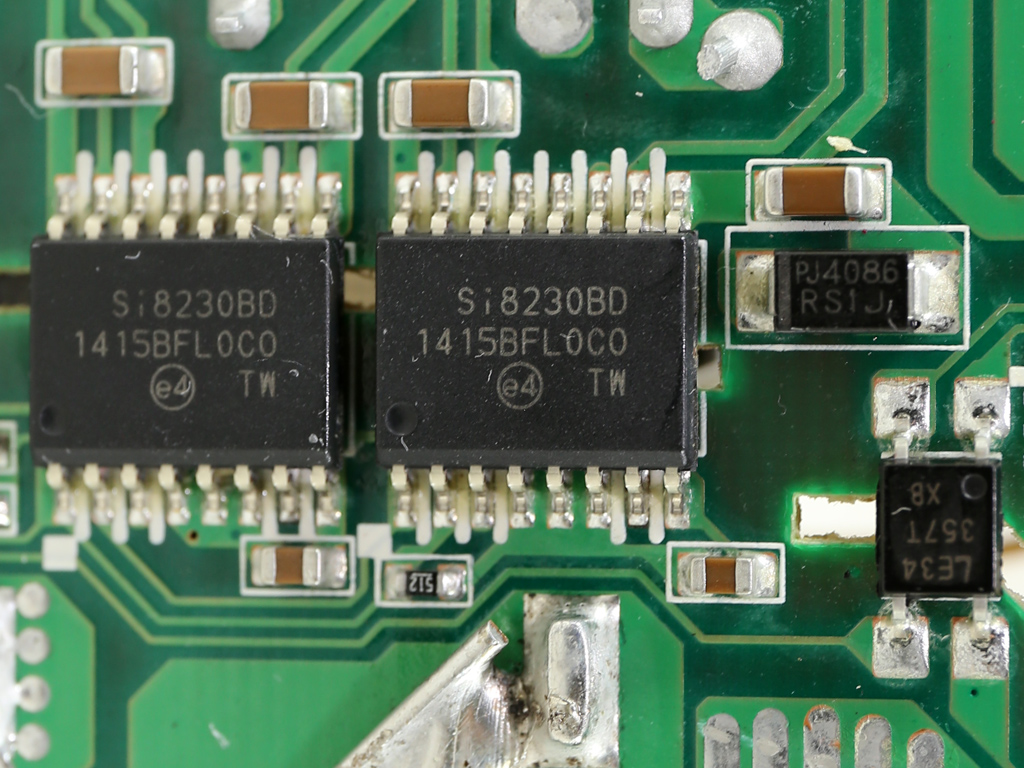
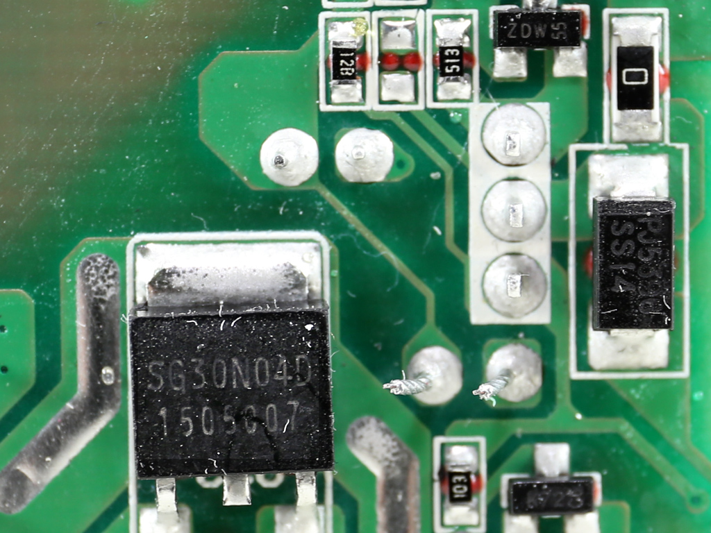
We found the LLC resonant controller, a Champion CM6901, and the supervisor IC which is a SITI PS223 on the solder side of the main PCB. This IC is among the very few with OTP (Over Temperature Protection). We also noticed two Silicon Labs Si8233BD isolators, which act as a bridge between the primary and secondary side. Finally, there is a SG30N04D FET on this side. It is most likely used by the 5VSB rail after the PSU is turned on.
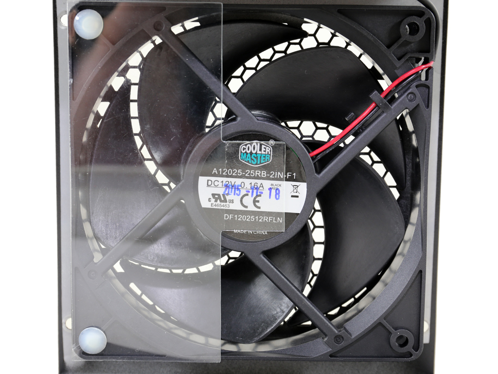
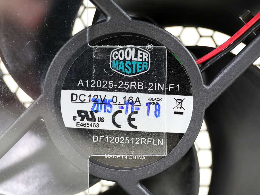
The fan uses a Loop Dynamic Bearing (LDB), which looks to be an FDB (Fluid Dynamic Bearing) derivative. Cooler Master claims this bearing to last for 160,000 hours. The older VSM550 and other VSM units use double ball-bearing fans, which are good, but not as good as this one, at least on papers. This LDB fan is also dust-proof, which will play a key role in its reliability.
Mar 10th, 2025 16:26 EDT
change timezone
Latest GPU Drivers
New Forum Posts
- DLSS as antialiasing? (20)
- Fix for Vram always at maximum (0)
- Maxsun RX580 graphics card crashes (25)
- Please I need help with the poor performance that my PC is giving me (28)
- Company of Heroes 3 (5)
- The TPU Darkroom - Digital SLR and Photography Club (4071)
- A Final Fantasy IX Reminiscence - My love letter and homage to one of the best stories ever told (72)
- Gaming PC instabiliity (20)
- Msi 5090 DOA? (27)
- 3D Printer Club (447)
Popular Reviews
- Sapphire Radeon RX 9070 XT Nitro+ Review - Beating NVIDIA
- XFX Radeon RX 9070 XT Mercury OC Magnetic Air Review
- ASUS Radeon RX 9070 TUF OC Review
- MSI MAG B850 Tomahawk Max Wi-Fi Review
- NVIDIA GeForce RTX 5080 Founders Edition Review
- NVIDIA GeForce RTX 5070 Founders Edition Review
- Corsair Vengeance RGB CUDIMM DDR5-8800 48 GB CL42 Review
- AMD Ryzen 7 9800X3D Review - The Best Gaming Processor
- ASUS GeForce RTX 5070 Ti TUF OC Review
- MSI GeForce RTX 5070 Ti Gaming Trio OC+ Review
Controversial News Posts
- NVIDIA GeForce RTX 50 Cards Spotted with Missing ROPs, NVIDIA Confirms the Issue, Multiple Vendors Affected (513)
- AMD Plans Aggressive Price Competition with Radeon RX 9000 Series (277)
- AMD Radeon RX 9070 and 9070 XT Listed On Amazon - One Buyer Snags a Unit (261)
- AMD RDNA 4 and Radeon RX 9070 Series Unveiled: $549 & $599 (260)
- AMD Mentions Sub-$700 Pricing for Radeon RX 9070 GPU Series, Looks Like NV Minus $50 Again (248)
- NVIDIA Investigates GeForce RTX 50 Series "Blackwell" Black Screen and BSOD Issues (244)
- AMD Radeon RX 9070 and 9070 XT Official Performance Metrics Leaked, +42% 4K Performance Over Radeon RX 7900 GRE (195)
- AMD Radeon RX 9070-series Pricing Leaks Courtesy of MicroCenter (158)