 18
18
Corsair HX850 V2 850 W Review
Ripple Measurements »Advanced Transient Response Tests
In these tests, we monitor the response of the PSU in two different scenarios. First, a transient load (11 A at +12 V, 5 A at 5 V, 6 A at 3.3 V, and 0.5 A at 5 VSB) is applied to the PSU for 50 ms, while the latter is working at a 20% load state. In the second scenario, the PSU, while working at 50% load, is hit by the same transient load. In both tests, we measure the voltage drops that the transient load causes, using our oscilloscope. In any case, the voltages should remain within the regulation limits defined by the ATX specification. We must stress here that the above tests are crucial, since they simulate transient loads that a PSU is very likely to handle (e.g., booting a RAID array, an instant 100% load of CPU/VGAs, etc.). We call these tests "Advanced Transient Response Tests" and they are designed to be very tough to master, especially for PSUs with capacities lower than 500 W.| Advanced Transient Response 20% | ||||
|---|---|---|---|---|
| Voltage | Before | After | Change | Pass/Fail |
| 12 V | 12.123V | 12.012V | 0.92% | Pass |
| 5 V | 5.066V | 4.950V | 2.29% | Pass |
| 3.3 V | 3.327V | 3.234V | 2.80% | Pass |
| 5VSB | 5.047V | 4.981V | 1.31% | Pass |
| Advanced Transient Response 50% | ||||
|---|---|---|---|---|
| Voltage | Before | After | Change | Pass/Fail |
| 12 V | 12.055V | 11.951V | 0.86% | Pass |
| 5 V | 5.029V | 4.936V | 1.85% | Pass |
| 3.3 V | 3.282V | 3.193V | 2.71% | Pass |
| 5VSB | 5.029V | 4.962V | 1.33% | Pass |
All voltage drops are well controlled, and the deviations are small even on the 3.3 V rail, which is usually the weak chain in these tests. Apparently, CWT did a good job in this platform and the response of all rails at dynamic loads is very good.
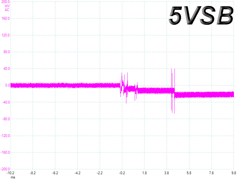
Below, you will see the oscilloscope screenshots that we took during the Advanced Transient Response Testing.
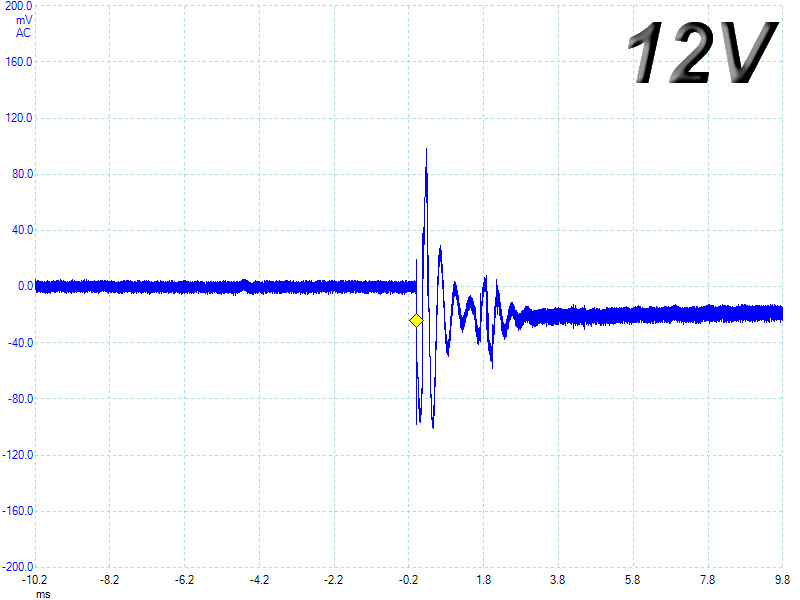
Transient Response at 20% Load
Transient Response at 50% Load
Turn-On Transient Tests
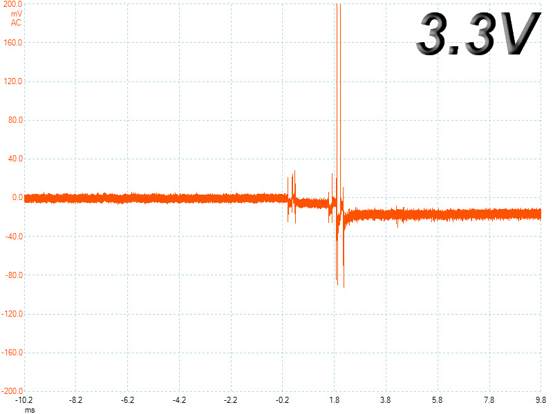
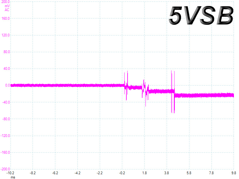
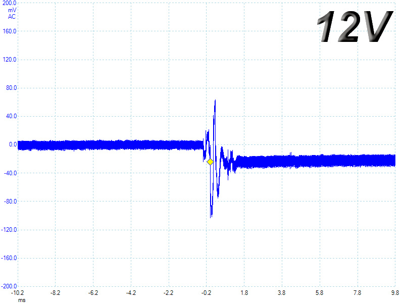
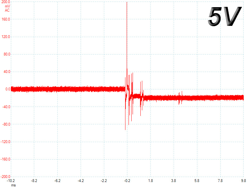
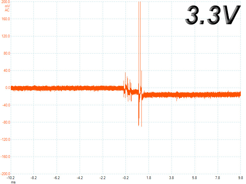
In the next set of tests, we measure the response of the PSU in simpler scenarios of transient loads, during the power-on phase of the PSU. In the first test, we turn off the PSU, dial 2 A of load at 5 VSB and then switch on the PSU. In the second test, while the PSU is in standby mode, we dial the maximum load that +12 V can handle and we start the PSU. In the last test, while the PSU is completely switched off (we cut off power or switch off the PSU's on/off switch), we dial the maximum load that the +12 V rail can handle and then we switch on the PSU from the loader and we restore power. The ATX specification states that recorded spikes on all rails should not exceed 10% of their nominal values (e.g., +10% for 12 V is 13.2 V and for 5 V is 5.5 V).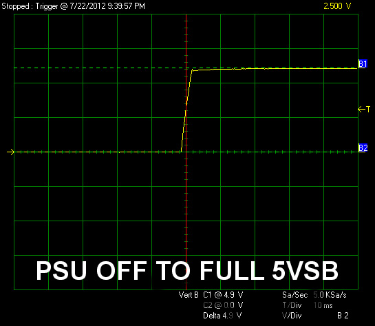
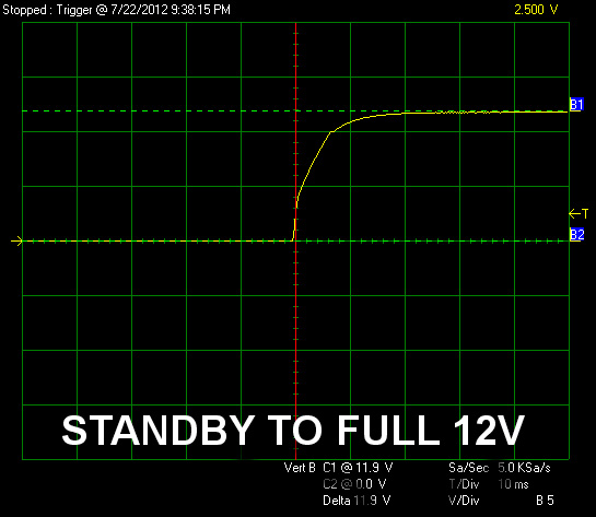
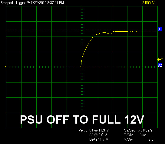
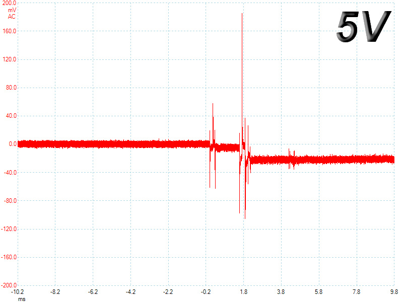
On the 5VSB rail, there is a minor spike, while on the "standby to full 12V" test the waveform ramps up smoothly. The worst result was obtained in the final test where the waveform made a noticeable wave, which, however, did not exceed the nominal voltage at its peak. Thankfully, the rise time on all three tests we conducted was constantly within the range specified by the ATX specifications (0.2-20 ms).
Jul 1st, 2025 22:49 CDT
change timezone
Latest GPU Drivers
New Forum Posts
- PCMA2305 Phase Change Metal Alloy (PCMA) (7)
- Best motherboards for XP gaming (18)
- What would you buy? (32)
- Is my m2 possibly fake ? and possible laptop hardware damage ? (28)
- HP Zbook 15 G2 GPU Upgrade (4)
- Help me overclocking my GSkill Ripjaws 3200MHz CL 16 DDR4 RAMs. (20)
- MACPRO 3,1 booting windows (0)
- My PCIe5 SSD is slow. Samsung 9100 PRO (29)
- Steering wheels, I think I had a mea culpa! (0)
- My PSU died.. (1)
Popular Reviews
- ASUS ROG Crosshair X870E Extreme Review
- Crucial T710 2 TB Review - Record-Breaking Gen 5
- Sapphire Radeon RX 9060 XT Pulse OC 16 GB Review - An Excellent Choice
- AVerMedia CamStream 4K Review
- Upcoming Hardware Launches 2025 (Updated May 2025)
- AMD Ryzen 7 9800X3D Review - The Best Gaming Processor
- Lexar NQ780 4 TB Review
- Sapphire Radeon RX 9070 XT Nitro+ Review - Beating NVIDIA
- AMD Ryzen 9 9950X3D Review - Great for Gaming and Productivity
- NVIDIA GeForce RTX 5060 8 GB Review
TPU on YouTube
Controversial News Posts
- Intel's Core Ultra 7 265K and 265KF CPUs Dip Below $250 (288)
- NVIDIA Grabs Market Share, AMD Loses Ground, and Intel Disappears in Latest dGPU Update (208)
- Some Intel Nova Lake CPUs Rumored to Challenge AMD's 3D V-Cache in Desktop Gaming (140)
- NVIDIA GeForce RTX 5080 SUPER Could Feature 24 GB Memory, Increased Power Limits (112)
- Microsoft Partners with AMD for Next-gen Xbox Hardware (105)
- NVIDIA Launches GeForce RTX 5050 for Desktops and Laptops, Starts at $249 (105)
- Intel "Nova Lake‑S" Series: Seven SKUs, Up to 52 Cores and 150 W TDP (100)
- NVIDIA DLSS Transformer Cuts VRAM Usage by 20% (91)