 7
7
EVGA SuperNOVA G2 1600 W Review
Load Regulation, Hold-up Time & Inrush Current »A Look Inside & Component Analysis
Before reading this page, we strongly suggest a look at this article, which will help you understand the internal components of a PSU much better. Our main tool for the disassembly of the PSU is a Thermaltronics TMT-9000S soldering and rework station. It is of extreme quality and is equipped with a matching de-soldering gun. With such equipment in hand, breaking apart every PSU is like a walk in the park!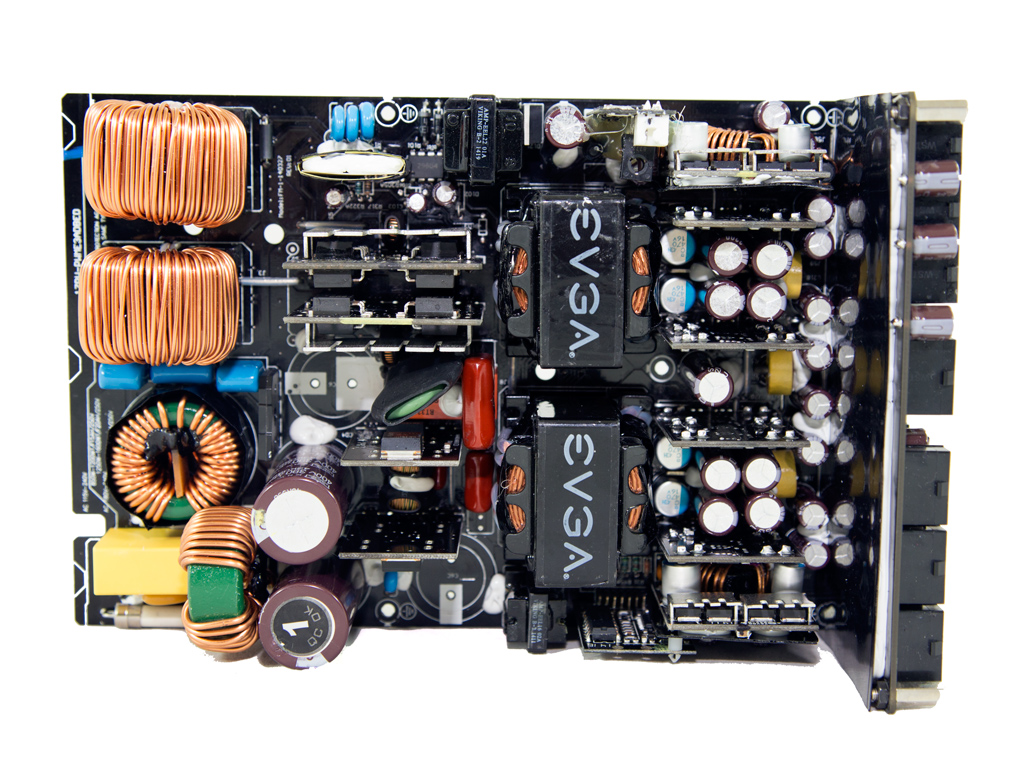
| EVGA G2-1600 Parts Description | |
|---|---|
| Primary Side | |
| Transient Filter | 6x Y caps, 2x X caps, 2 CM chokes, 1x MOV |
| Bridge Rectifier(s) | Bridgeless Design - 1x US30K80R & 8x Infineon Mosfets |
| APFC Mosfets | 8x Infineon 60R125 Mosfets |
| APFC Boost Diode | 4x C3D08060G |
| Hold-up Cap(s) | 4x Nippon Chemi-Con (400V, 390uF each. 1560uF combined, 105°C, KMR) |
| Main Switchers | 4x Infineon 5R140P |
| APFC Controller | SF29603 |
| Switching Controller | SFAA9013 |
| Topology | Bridgeless PFC & Full-Bridge LLC & Resonant Converter |
| Secondary Side | |
| +12V | 16x Infineon BSC035N04LS |
| 5V & 3.3V | DC-DC Converters: 8x Infineon IPD060N03 fets |
| Filtering Capacitors | Electrolytics: Chemi-Con, 105°C, KY Polymers: Chemi-Con |
| Supervisor IC | AA9013 (probably) & LM324ADG |
| Fan Model | Globe Fan RL4Z-B1402512EH (140 mm, 12 V, 0.6 A, 2000 RPM, 153.47 CFM, 39.5 dBA, 70.000 MTBF) |
| 5VSB Circuit | |
| Rectifying Diode | Mospec S10C60C |
| Standby PWM Controller | 29604 |


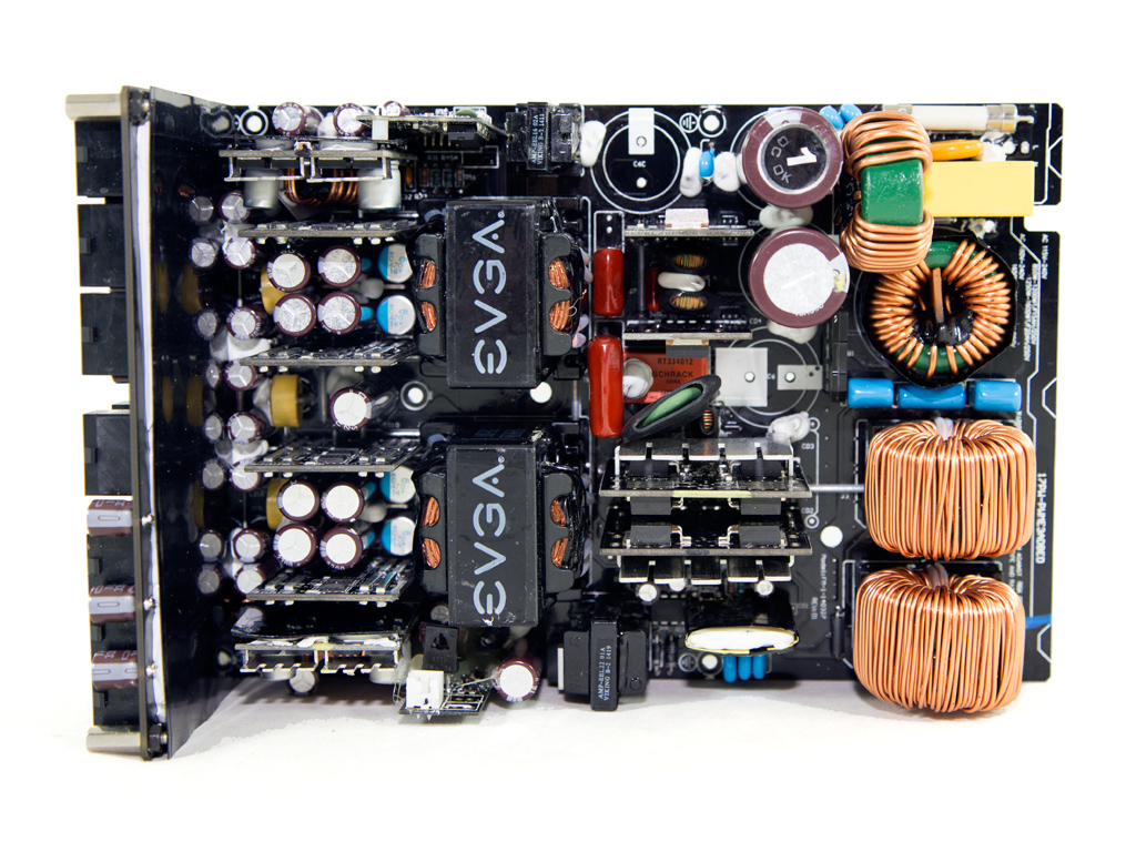
Once we opened its case, we were gazing at a new platform that has nothing in-common with Super Flower's Leadex platform. When we heard of the G2-1600, we thought it would use an enhanced Leadex platform, but we were wrong as SF had another ace up its sleeve. This new design actually doesn't use any of the conventionally huge heatsinks found in PSUs of similar wattage, and it probably doesn't feature a semi-passive operation because it lacks such heatsinks. The design in the APFC is unique and employs a large number of mosfets and diodes which actually act as rectifying bridges, while a series of daughter-boards in the secondary side house the +12V fets. This unit uses a Bridgeless PFC and a full bridge topology with an LLC resonant converter for increased efficiency.
Behind the AC receptacle is a small PCB without any of the transient filter's components. The latter are installed on the main PCB and include three pairs of Y caps, a pair of X ones, an MOV, and two CM chokes. All in all, the transient filter is complete.
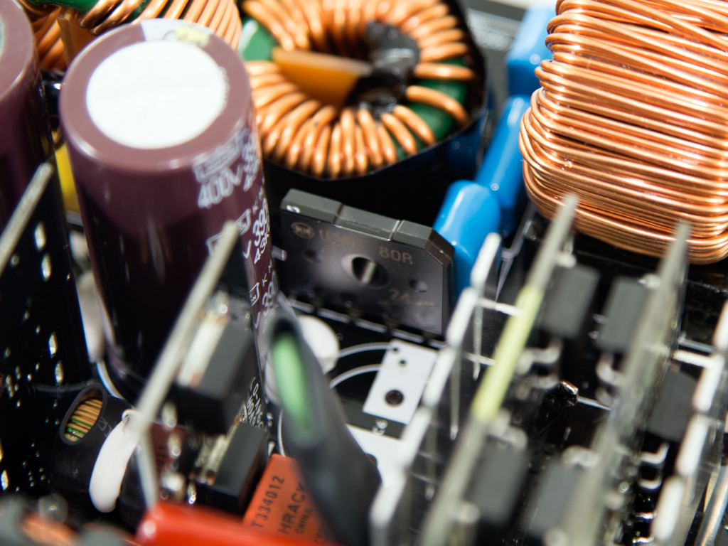
We, strangely enough, only found a single bridge rectifier, a US30K80R. While powerful, it is not attached to a heatsink, so it will probably not be able to handle its limit, 30 A. This unit essentially uses a bridge-less design since the main rectification takes part in the APFC converter and is done by mosfets, which lose less energy compared to diodes.
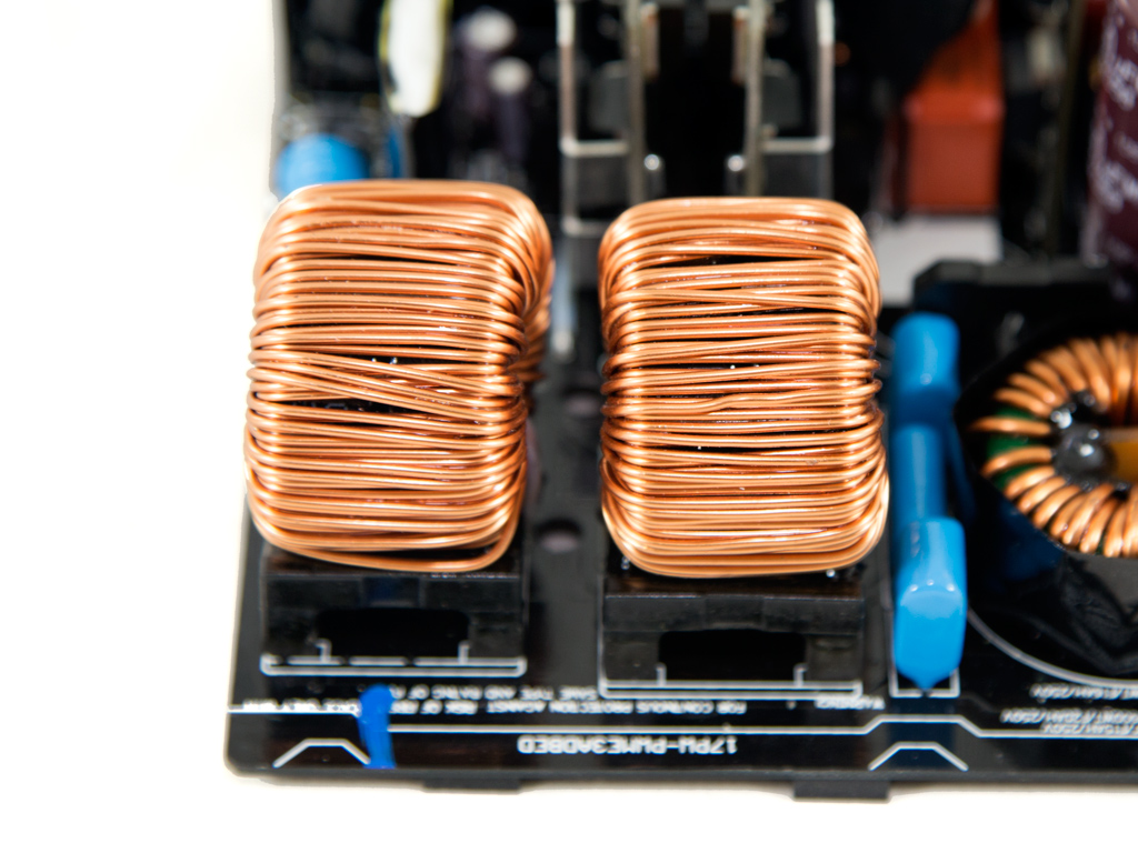

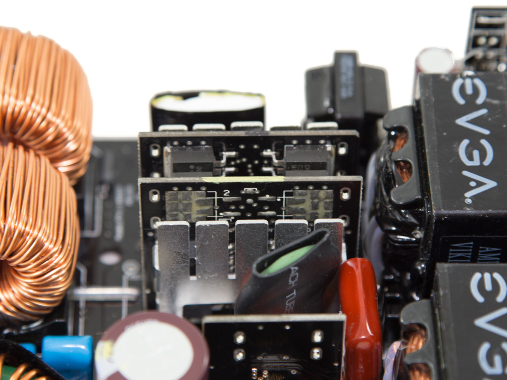


We found a pair of daughter-boards, full of components, and two large coils in the APFC converter. To be more specific, each of the aforementioned boards houses four Infineon 60R125 fets which are protected against EMI by metal shields and two C3D08060G boost diodes. One or even both of these boards most likely fully rectify the incoming alternating current (AC) voltage. Four parallel Nippon Chemi-Cons are used as bulk caps (400 V, 390 uF each or 1560 uF combined, 105°C, KMR), and our tests proved that their combined capacity is enough for the unit's needs.

The PFC controller, a proprietary IC with code name SF29603, is on this shielded board.

As per usual, an NTC thermistor protects the unit against large inrush currents, and it has its own relay to cut it off the circuit as needed.
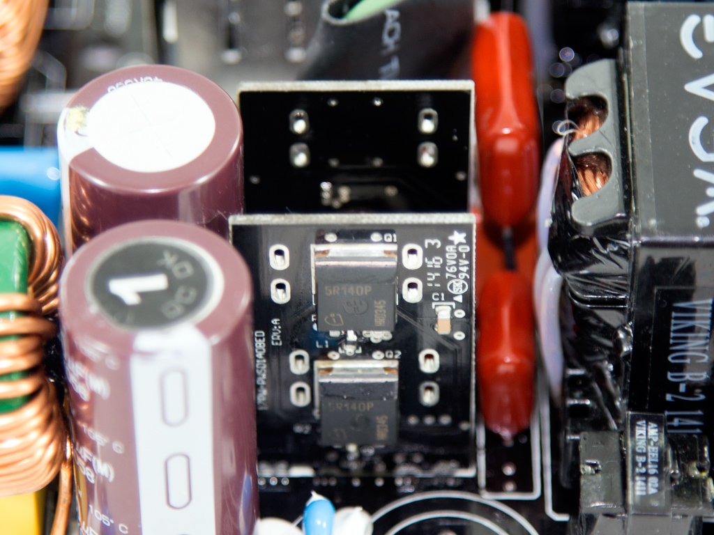
Two boards hold all the main switchers, four Infineon 5R140P arranged into a full-bridge topology. Also, an LLC converter is used to boost efficiency.
Since there wasn't enough space for a single huge main transformer, two in parallel were used instead.
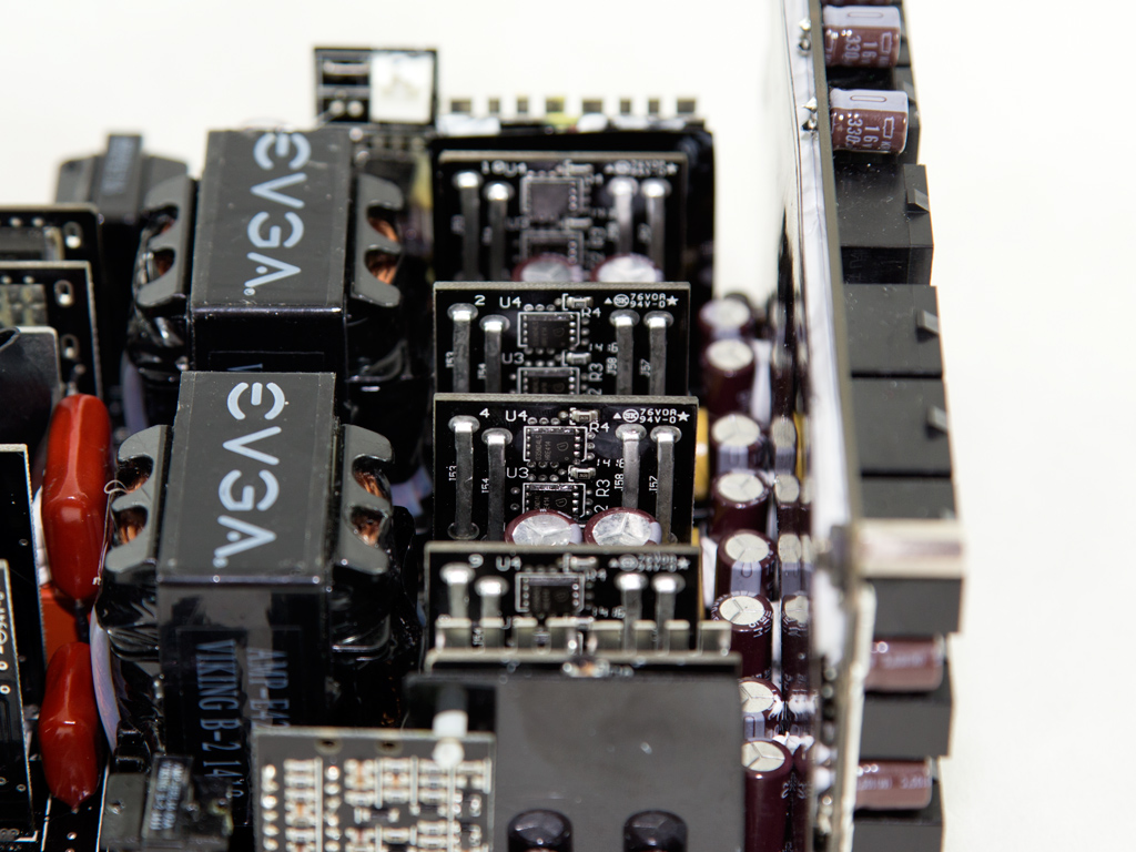

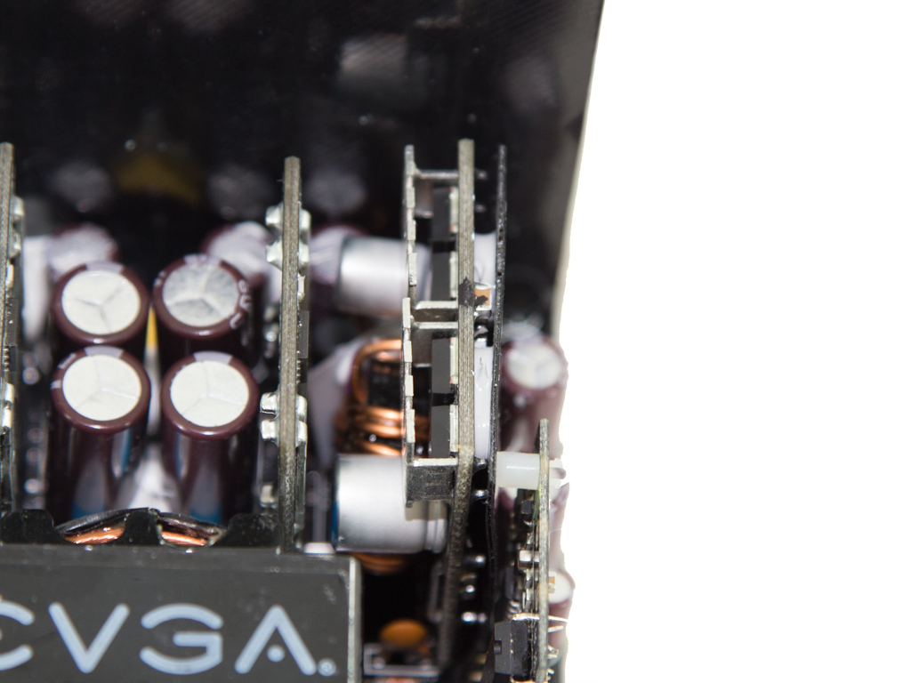
Not one or two but four vertical PCBs in the secondary side house all mosfets that regulate +12V. In total, 16 Infineon BSC035N04LS fets are designated to the task. We can't think of another PSU with as many fets for this rail's regulation.
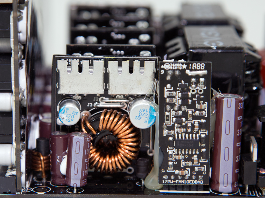

Two DC-DC converters, located far from one another, handle the minor rails. Each converter uses four Infineon IPD060N03 fets. Right next to one of these boards is the fan controlling circuit's PCB, along with a Mospec S10C60C SBR that generates the 5VSB rail. This particular PCB also houses an LM324ADG.

The standby PWM controller only has a number written on it, "29604", and it didn't prove useful in identifying the controller.

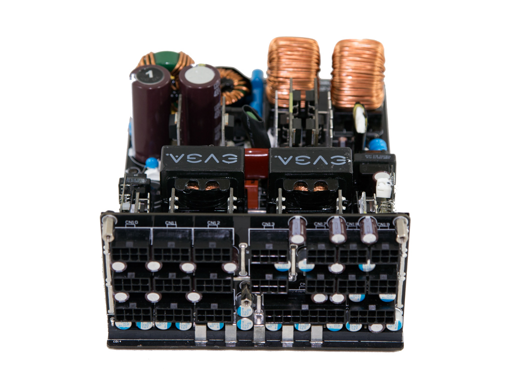
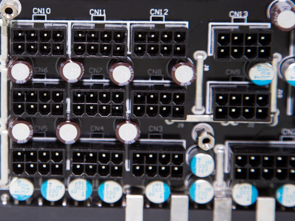
All filtering capacitors in the secondary side, both electrolytic and polymer, are provided by Nippon Chemi-Con, so they are of very high quality.


On the other side of this daughter-board is the resonant controller, an AA9013 IC for which there is no available information. There is also a well-hidden LM324ADG on the same board.


The PCB's rear is insulated by tape, and the many filtering capacitors toward its front, electrolytics and polymers, are all provided by Chemi-Con.
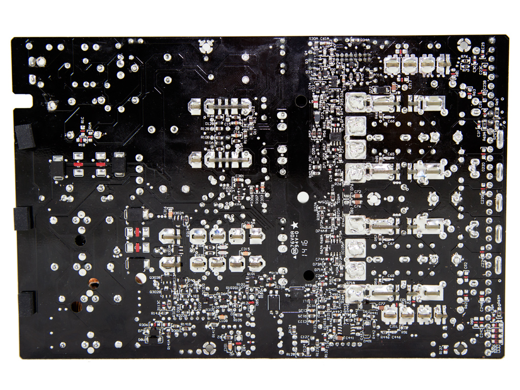
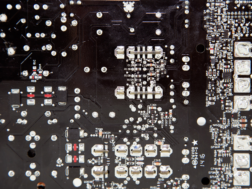


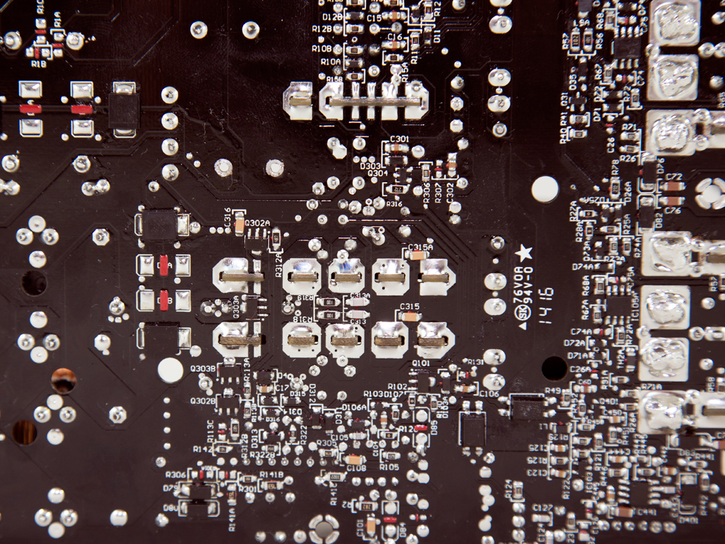
Soldering quality is even better than on the Leadex platforms. Super Flower has progressed nicely in this section; however, they still haven't caught up to such OEMs as Delta.
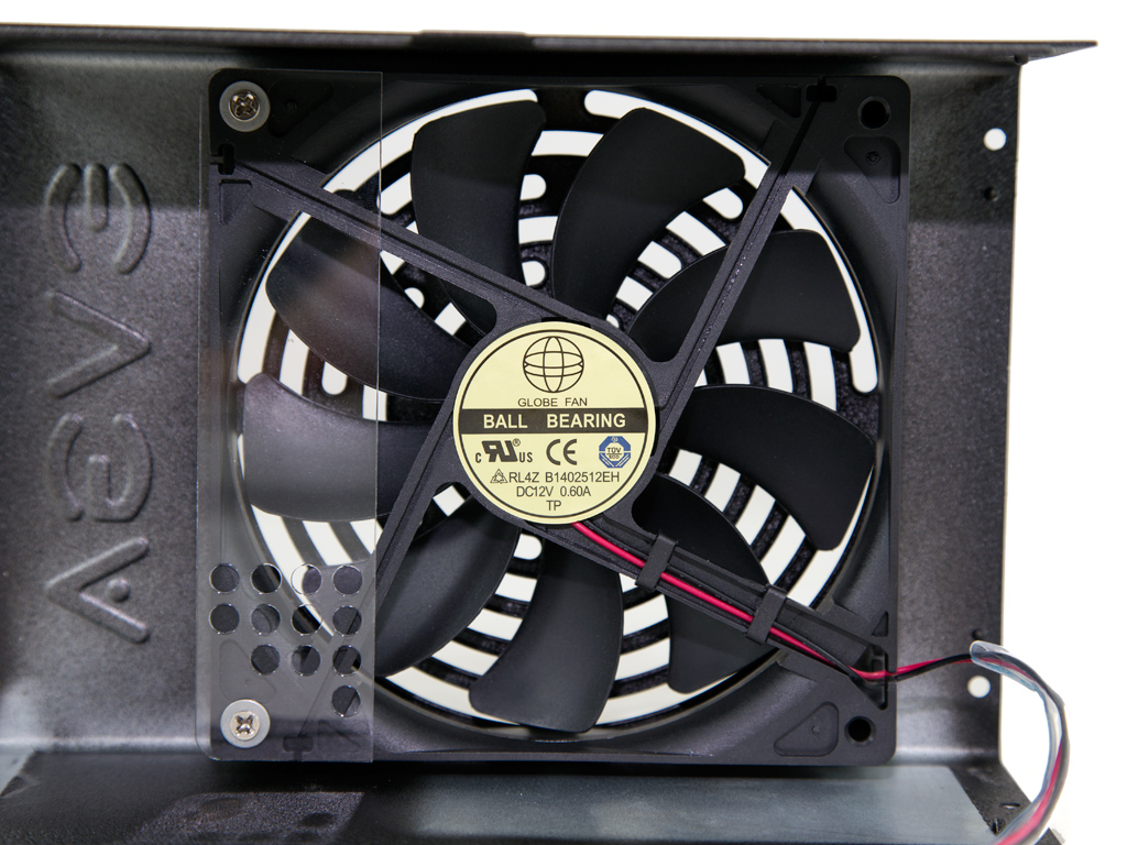
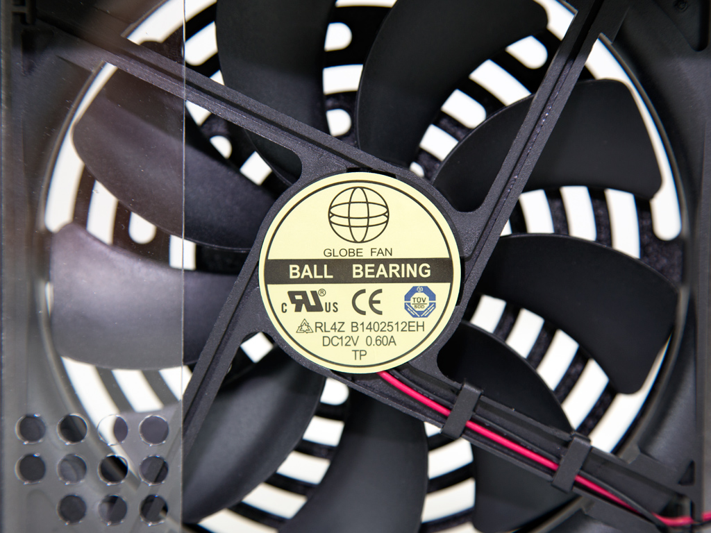
The cooling fan is the same as in the P2-1200, a fan by Globe Fan. Its model number is RL4Z-B1402512EH (140 mm, 12 V, 0.6 A, 2000 RPM, 153.47 CFM, 39.5 dBA, 70.000 MTBF), and it is equipped with double ball-bearings for better longevity. This unit doesn't feature a semi-passive mode, but contrary to other SF units, its fan-control circuit provides many operational modes—speed profiles—which will, depending on ambient conditions, vary fan speed a lot as there are more than three or four available modes.
Feb 1st, 2025 22:44 EST
change timezone
Latest GPU Drivers
New Forum Posts
- Ryzen 9 7950x with a 7900 xtx gpu. (13)
- Starting my AM5 build (3)
- Youtube Channel (15)
- remove hum from active subwoofer? (25)
- MSI Vector 17 HX A14VIG "EDP OTHER" (14)
- RTX 5080 - premature review - it sucks (173)
- TPU's F@H Team (20404)
- QVL - Myth, Legend, Marketing/Advertising, what is your take? (40)
- What Router Are You Using For Your Computer (58)
- TPU's Nostalgic Hardware Club (19920)
Popular Reviews
- NVIDIA GeForce RTX 5080 Founders Edition Review
- Galax GeForce RTX 5080 1-Click OC Review
- NVIDIA DLSS 4 Transformer Review - Better Image Quality for Everyone
- MSI GeForce RTX 5080 Vanguard SOC Review
- ASUS GeForce RTX 5080 Astral OC Review
- Gigabyte GeForce RTX 5080 Gaming OC Review
- MSI GeForce RTX 5080 Suprim SOC Review
- ASUS GeForce RTX 5090 Astral OC Review - Astronomical Premium
- Spider-Man 2 Performance Benchmark Review - 35 GPUs Tested
- NVIDIA GeForce RTX 5090 Founders Edition Review - The New Flagship
Controversial News Posts
- NVIDIA 2025 International CES Keynote: Liveblog (470)
- AMD Debuts Radeon RX 9070 XT and RX 9070 Powered by RDNA 4, and FSR 4 (349)
- AMD is Taking Time with Radeon RX 9000 to Optimize Software and FSR 4 (251)
- AMD Denies Radeon RX 9070 XT $899 USD Starting Price Point Rumors (238)
- AMD Radeon 9070 XT Rumored to Outpace RTX 5070 Ti by Almost 15% (234)
- AMD Radeon RX 9070 XT & RX 9070 Custom Models In Stock at European Stores (226)
- NVIDIA GeForce RTX 5090 Features 575 W TDP, RTX 5080 Carries 360 W TDP (217)
- New Leak Reveals NVIDIA RTX 5080 Is Slower Than RTX 4090 (215)