 6
6
Fractal Design NEWTON R3 1000 W Review
Ripple Measurements »Advanced Transient Response Tests
In these tests, we monitor the response of the PSU in two different scenarios. First, a transient load (10 A at +12V, 5 A at 5V, 5 A at 3.3V, and 0.5 A at 5VSB) is applied to the PSU for 200 ms while the latter is working at a 20% load state. In the second scenario, the PSU, while working at 50% load, is hit by the same transient load. In both tests, we measure the voltage drops that the transient load causes using our oscilloscope. The voltages should remain within the regulation limits defined by the ATX specification. We must stress here that the above tests are crucial since they simulate transient loads that a PSU is very likely to handle (e.g., booting a RAID array, an instant 100% load of CPU/VGAs, etc.) We call these tests "Advanced Transient Response Tests", and they are designed to be very tough to master, especially for PSUs with capacities lower than 500 W.| Advanced Transient Response 20% | ||||
|---|---|---|---|---|
| Voltage | Before | After | Change | Pass/Fail |
| 12 V | 12.125V | 12.016V | 0.90% | Pass |
| 5 V | 5.052V | 4.960V | 1.82% | Pass |
| 3.3 V | 3.332V | 3.204V | 3.84% | Pass |
| 5VSB | 5.073V | 5.039V | 0.67% | Pass |
| Advanced Transient Response 50% | ||||
|---|---|---|---|---|
| Voltage | Before | After | Change | Pass/Fail |
| 12 V | 12.088V | 12.002V | 0.71% | Pass |
| 5 V | 5.044V | 4.952V | 1.82% | Pass |
| 3.3 V | 3.309V | 3.163V | 4.41% | Pass |
| 5VSB | 5.036V | 4.993V | 0.85% | Pass |
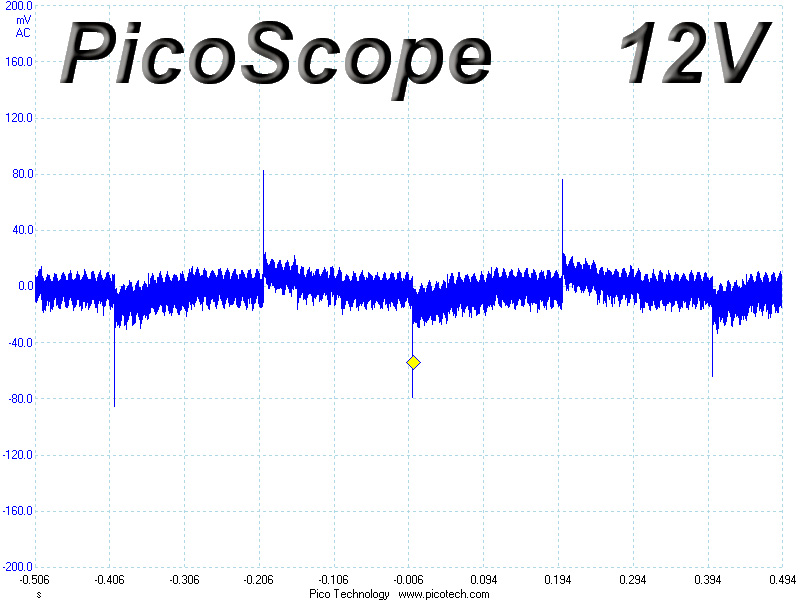
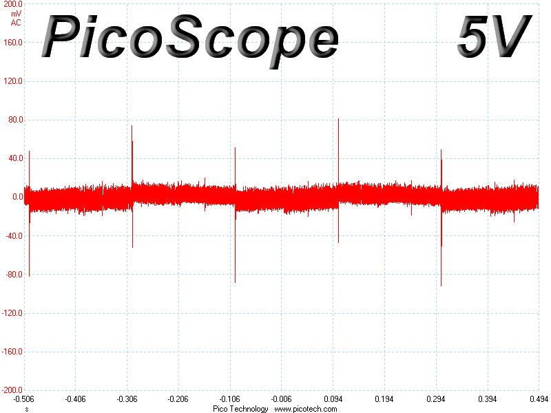
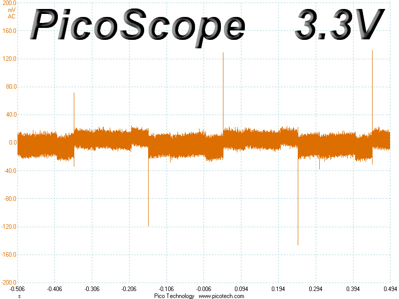
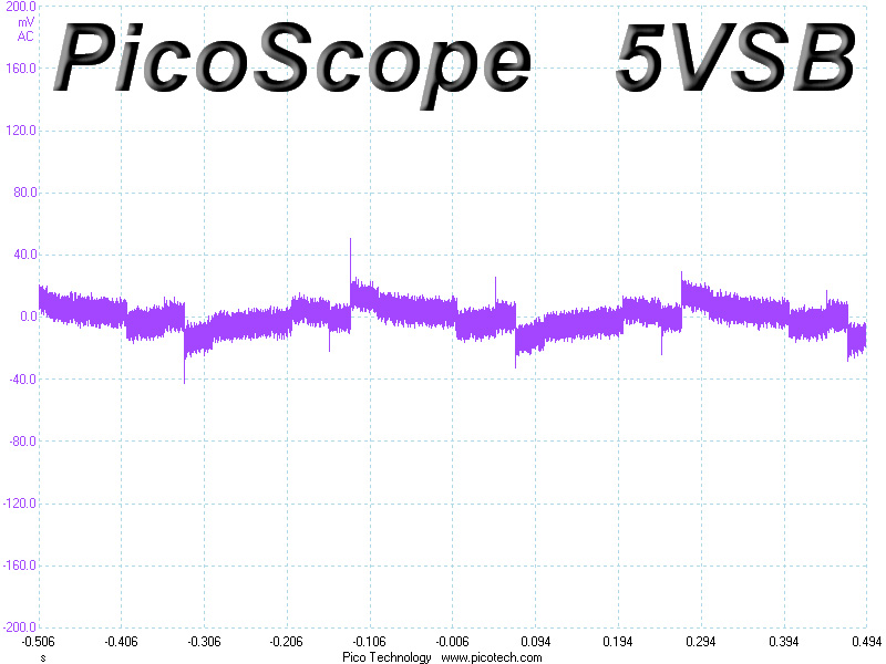
The response of the +12V rail to transient loads is very good. Its deviation stayed under 1% on both tests. Voltage drops at 5V and 5VSB were low as well, but the deviations of the 3.3V rail lead to readings below 3.2V, especially on the second test. We don't like seeing such low readings at 3.3V, even if they are instantaneous on these tests.
Below, you will find the oscilloscope screenshots that we took during Advanced Transient Response Testing.
Transient Response at 20% Load
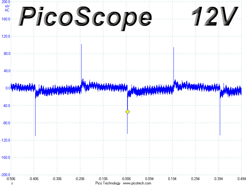
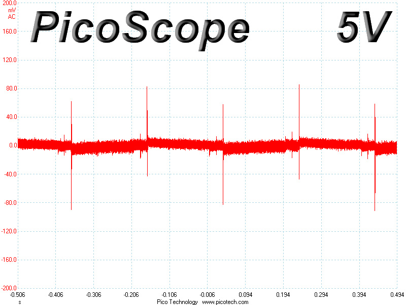
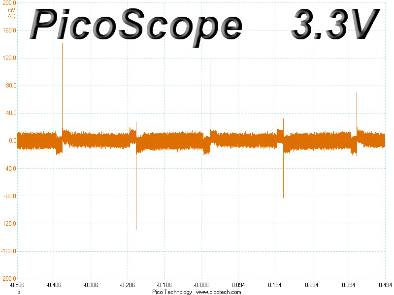
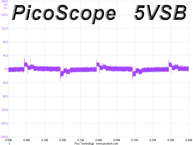
Transient Response at 50% Load
Turn-On Transient Tests
We measure the response of the PSU in simpler scenarios of transient loads - during the power-on phase of the PSU - in the next set of tests. In the first test, we turn the PSU off, dial the maximum current that the 5VSB can output, and switch the PSU on. In the second test, we dial the maximum load that +12V can handle and start the PSU while the PSU is in standby mode. In the last test, while the PSU is completely switched off (we cut off power or switch off the PSU's on/off switch), we dial the maximum load that the +12V rail can handle before switching the PSU on from the loader and restoring power. The ATX specification states that recorded spikes on all rails should not exceed 10% of their nominal values (e.g., +10% for 12V is 13.2V and for 5.5V for 5V).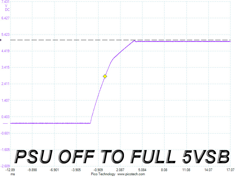
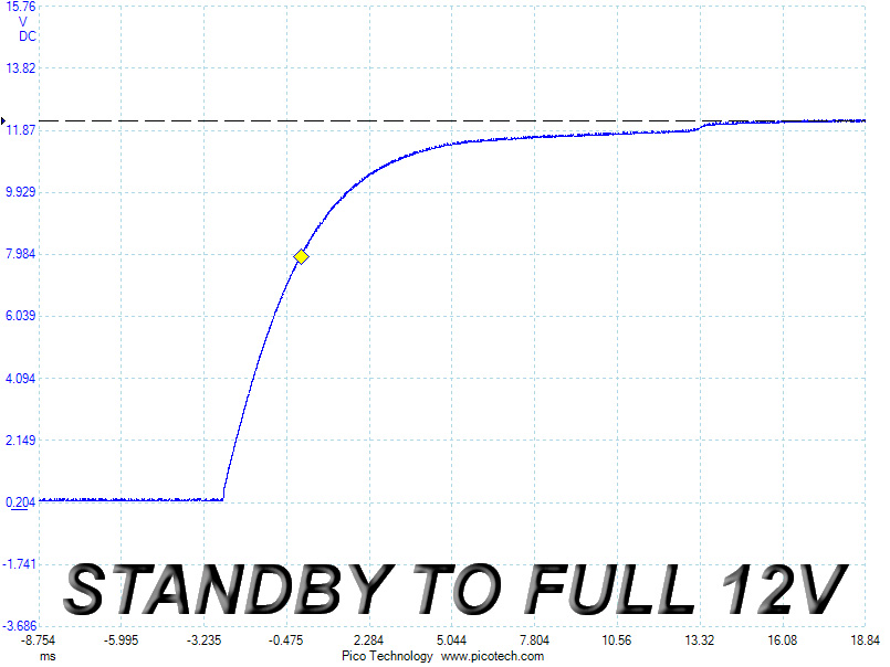
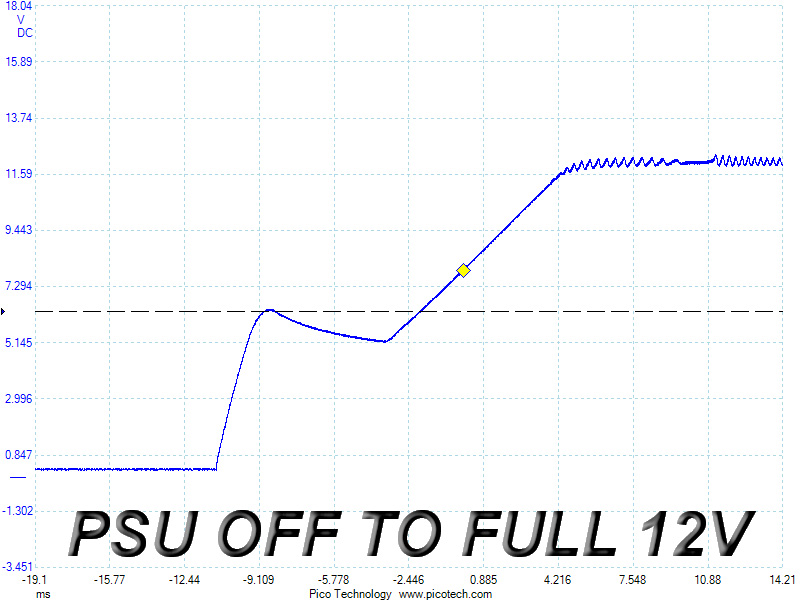
We measured a small voltage overshoot at 5VSB, while the slope was almost perfect on the second test. The slope made a large step at around 6.5 V on the last test and produced a nasty sawtooth wave when it reached the nominal voltage. Definitely not the ideal waveform according to the ATX spec, but all the registered spikes were still well below the limit.
Jul 5th, 2025 17:58 CDT
change timezone
Latest GPU Drivers
New Forum Posts
- EVGA XC GTX 1660 Ti 8GB ROM (11)
- How do you view TPU & the internet in general? (With poll) (79)
- What are you playing? (23893)
- Do you use Linux? (677)
- Optane performance on AMD vs Intel (58)
- Frametime spikes and stuttering after switching to AMD CPU? (521)
- Stalker 2 is looking great. (187)
- b550m aorus elite not posting with new ram (7)
- Gigabyte graphic cards - TIM gel SLIPPAGE problem (131)
- Can you guess Which game it is? (203)
Popular Reviews
- NVIDIA GeForce RTX 5050 8 GB Review
- Fractal Design Scape Review - Debut Done Right
- Crucial T710 2 TB Review - Record-Breaking Gen 5
- ASUS ROG Crosshair X870E Extreme Review
- PowerColor ALPHYN AM10 Review
- Sapphire Radeon RX 9060 XT Pulse OC 16 GB Review - An Excellent Choice
- Upcoming Hardware Launches 2025 (Updated May 2025)
- AMD Ryzen 7 9800X3D Review - The Best Gaming Processor
- Sapphire Radeon RX 9070 XT Nitro+ Review - Beating NVIDIA
- NVIDIA GeForce RTX 5060 8 GB Review
TPU on YouTube
Controversial News Posts
- Intel's Core Ultra 7 265K and 265KF CPUs Dip Below $250 (288)
- NVIDIA Grabs Market Share, AMD Loses Ground, and Intel Disappears in Latest dGPU Update (212)
- Some Intel Nova Lake CPUs Rumored to Challenge AMD's 3D V-Cache in Desktop Gaming (140)
- NVIDIA GeForce RTX 5080 SUPER Could Feature 24 GB Memory, Increased Power Limits (115)
- Microsoft Partners with AMD for Next-gen Xbox Hardware (105)
- NVIDIA Launches GeForce RTX 5050 for Desktops and Laptops, Starts at $249 (105)
- AMD Radeon RX 9070 XT Gains 9% Performance at 1440p with Latest Driver, Beats RTX 5070 Ti (102)
- Intel "Nova Lake‑S" Series: Seven SKUs, Up to 52 Cores and 150 W TDP (100)