 3
3
FSP Hydro G Series 750 W Review
Ripple Measurements »Advanced Transient Response Tests
These tests monitor the PSU's response in two different scenarios. First, a transient load (10 A at +12V, 5 A at 5V, 5 A at 3.3V, and 0.5 A at 5VSB) is applied to the PSU for 200 ms while the latter is working at 20% load. In the second scenario, the PSU, while working at 50% load, is hit by the same transient load. In both tests, we measure the voltage drops the transient load causes using our oscilloscope. The voltages should remain within the regulation limits defined by the ATX specification. We must stress here that these tests are crucial since they simulate transient loads a PSU is very likely to handle (e.g., booting a RAID array, an instant 100% load of CPU/VGAs, etc.). We call these Advanced Transient Response tests, and they are designed to be very tough to master, especially for a PSU with a capacity below 500 W.| Advanced Transient Response 20% | ||||
|---|---|---|---|---|
| Voltage | Before | After | Change | Pass/Fail |
| 12 V | 12.143V | 11.923V | 1.81% | Pass |
| 5 V | 5.161V | 5.045V | 2.25% | Pass |
| 3.3 V | 3.379V | 3.264V | 3.40% | Pass |
| 5VSB | 5.128V | 5.089V | 0.76% | Pass |
| Advanced Transient Response 50% | ||||
|---|---|---|---|---|
| Voltage | Before | After | Change | Pass/Fail |
| 12 V | 12.085V | 11.977V | 0.89% | Pass |
| 5 V | 5.131V | 5.017V | 2.22% | Pass |
| 3.3 V | 3.338V | 3.232V | 3.18% | Pass |
| 5VSB | 5.080V | 5.037V | 0.85% | Pass |
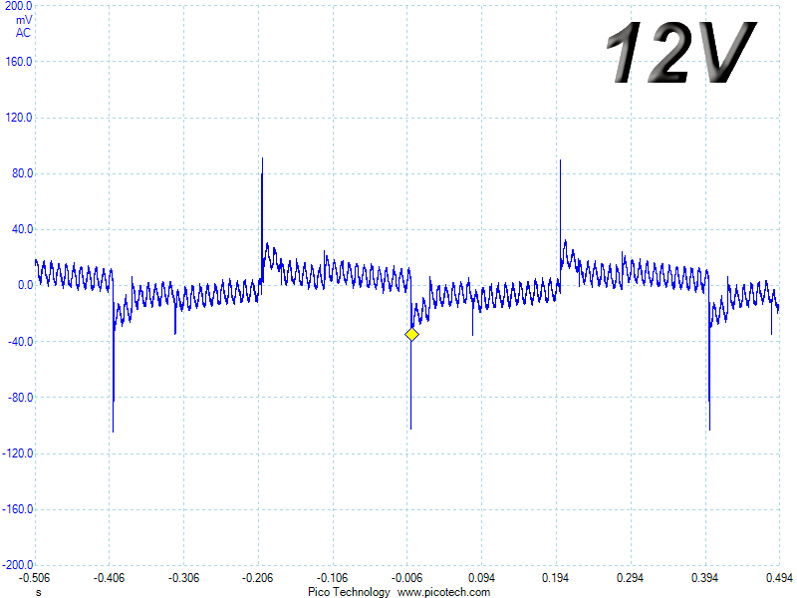
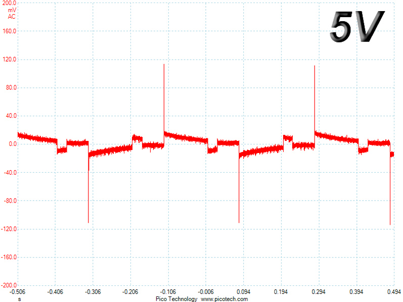
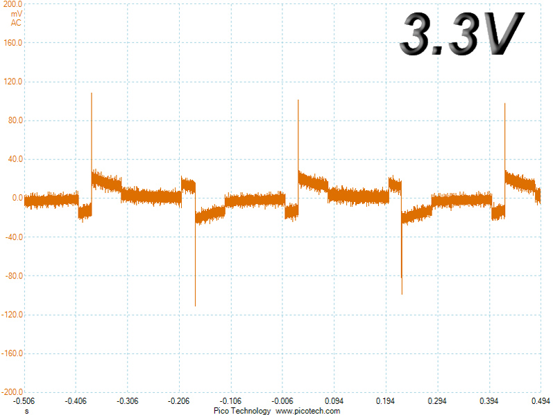
A better result at +12V wasn't possible in the first test because the main switchers were PWM operated; however, the same rail only registered deviations within 1% in the second test. Results were pretty good on the other rails, and to our surprise, voltage drops on the 3.3V rail were well controlled in both cases.
Below are the oscilloscope screenshots we took during Advanced Transient Response testing.
Transient Response at 20% Load
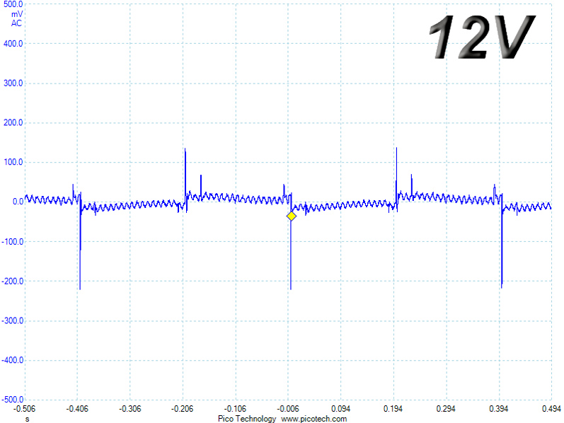
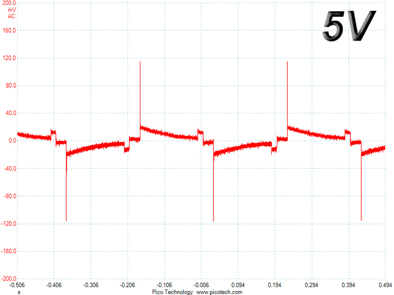
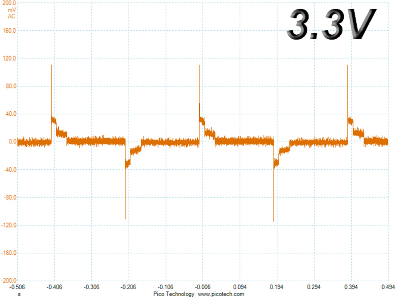
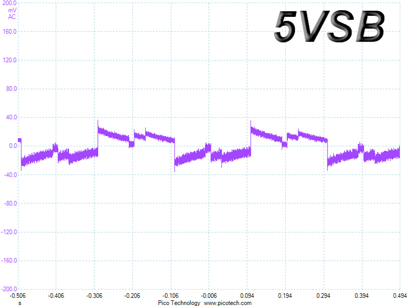
Transient Response at 50% Load
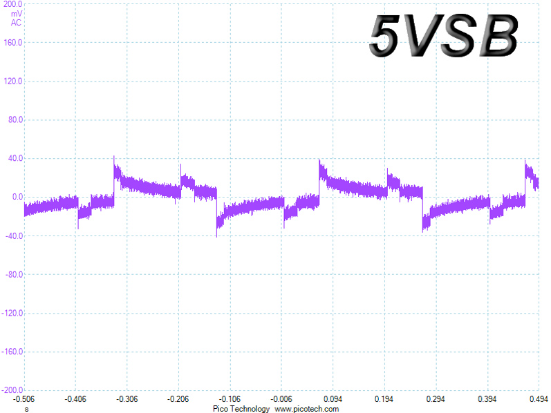
Turn-On Transient Tests
We measure the response of the PSU in simpler scenarios of transient load—during the power-on phase of the PSU—in the next set of tests. In the first test, we turn the PSU off, dial the maximum current the 5VSB can output, and switch on the PSU. In the second test, we dial the maximum load +12V can handle and start the PSU while the PSU is in standby mode. In the last test, while the PSU is completely switched off (we cut off power or switch the PSU off by flipping its on/off switch), we dial the maximum load the +12V rail can handle before switching the PSU on through the loader and restoring power. The ATX specification states that recorded spikes on all rails should not exceed 10% of their nominal values (e.g., +10% for 12V is 13.2V and 5.5V for 5V).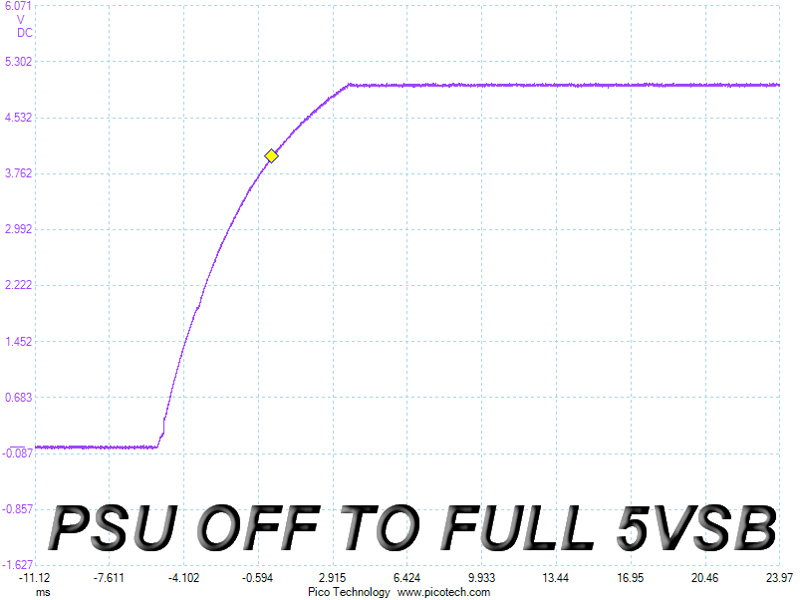
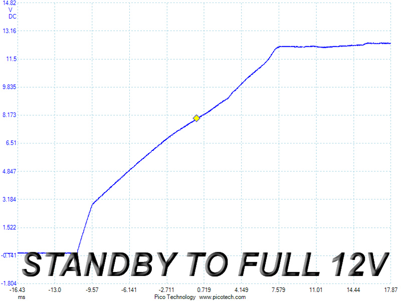
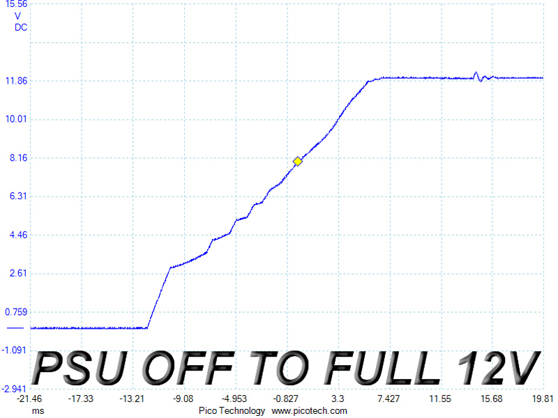
The 5VSB slope was very smooth, though the rail took some time before reaching its nominal voltage in the second test, and there were a few small steps between 3-6 V in the third test; however, those are nothing to worry about. Rise times were also within the ATX specification's range of 0.2-20 ms.
Jan 9th, 2025 15:44 EST
change timezone
Latest GPU Drivers
New Forum Posts
- thermal limiting on i5 8265u, pls HELP (1)
- Scientists build first light based hardware that competes with silicon (18)
- Power supply or motherboard (19)
- Best time to sell your used 4090s is now. (163)
- Nvidia drivers versus AMD drivers on Wayland (34)
- Your PC ATM (35172)
- Are people planning an upgrade? (132)
- PC stuttering after updating to Windows 11 and installing Nvidia drivers, polling rate fixes it? (3)
- What are you playing? (22549)
- Looking for 10" android tablet (1)
Popular Reviews
- ASUS ROG Strix B850-F Gaming WiFi Review
- AMD Ryzen 7 9800X3D Review - The Best Gaming Processor
- DDR5 Thermal Testing & Analysis
- HEDDphone TWO GT Air Motion Transformer Headphones Review
- Royal Kludge S85 TKL Wireless Mechanical Keyboard Review
- GPU Test System Update for 2025
- Call of Duty: Black Ops 6 Performance Benchmark Review - AMD FTW
- Upcoming Hardware Launches 2024 (Updated Nov 2024)
- Intel Arc B580 Review - Excellent Value
- SCYROX V8 Review
Controversial News Posts
- NVIDIA 2025 International CES Keynote: Liveblog (446)
- AMD Debuts Radeon RX 9070 XT and RX 9070 Powered by RDNA 4, and FSR 4 (339)
- NVIDIA GeForce RTX 5090 Features 575 W TDP, RTX 5080 Carries 360 W TDP (209)
- AMD Radeon RX 9070 XT Alleged Benchmark Leaks, Underwhelming Performance (204)
- Potential RTX 5090 and RTX 5080 Pricing in China Leaks (173)
- 32 GB NVIDIA RTX 5090 To Lead the Charge As 5060 Ti Gets 16 GB Upgrade and 5060 Still Stuck With Last-Gen VRAM Spec (173)
- AMD Radeon RX 9070 XT Boosts up to 3.10 GHz, Board Power Can Reach up to 330W (167)
- NVIDIA GeForce RTX 5070 Ti Leak Tips More VRAM, Cores, and Power Draw (161)