 6
6
FSP Twins 500 W Redundant PSU Review
EMC Pre-Compliance Testing »Protection Features Evaluation
Every PSU should be equipped with a protections set that will not only protect the PSU, but the whole system it feeds. You can learn more about PSU protections by reading through the corresponding section of our "A Detailed Look Into PSUs" article.In a snap, the most important protections for PSUs are the following:
- Over Current Protection (OCP)
- Over Power Protection (OPP)
- Over Temperature Protection (OTP)
- Over/Under Voltage Protection (OVP/UVP)
- Short Circuit Protection (SCP)
- No-load Operation (NLO)
- Surge & Inrush Protection (SIP)
| Protection Features | |
|---|---|
| OCP | 12V1/2/3: >41A 5V: 28A (140%) 3.3V: 28.7A (143.5%) 5VSB: 10A (303.3%), 4.655V |
| OPP | 608.094W (121.6%) |
| OTP | ✓ (105°C @ Secondary Side) |
| SCP | 12V: ✓ 5V: ✓ 3.3V: ✓ 5VSB: ✓ -12V: ✓ |
| PWR_OK | Proper Operation |
| NLO | ✓ |
| SIP | Surge: MOV Inrush: NTC & Bypass Relay |
The over-power protection feature is set to normal levels, while OCP is high on all rails, especially at 5VSB where it should be set much lower.
FSP neglected mentioning it, but OTP is present and properly configured. OTP is essential, especially in server-oriented PSUs with high power density. Lastly, there is fan-failure protection as well, which we confirmed to work as it should. The module will shut down should the fan of one of these modules break or simply disconnect. There is also short-circuit protection on all rails, and the power-good signal is accurate since it drops before the rails go out of spec.
Since this frame hosts two power modules, one of which will fully take over should the other break down, we had to run some tests to check on transitioning times, and on how smoothly the transition actually takes place in terms of +12V output. This wasn't easily done, but our advanced (and very expensive) scope allowed us to do so successfully. For the following tests, we applied a full load (500 W) to the PSU.
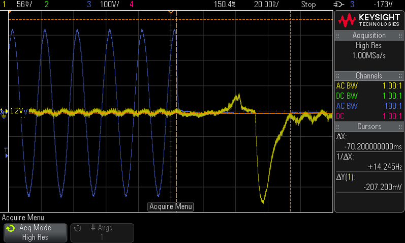
Here's the moment we cut power to the first module. As you can see in the screenshot above, the total time between the drop in power and the second module stabilizing the +12V rail is 70.2 ms. FSP used large bulk caps to facilitate a smooth transition. The long hold-up time is a major advantage in this particular case.
The peak voltage overshoot is 40.6mV, while the voltage drop reaches 203.7mV. This means that the +12V rail stays within spec during the transition.
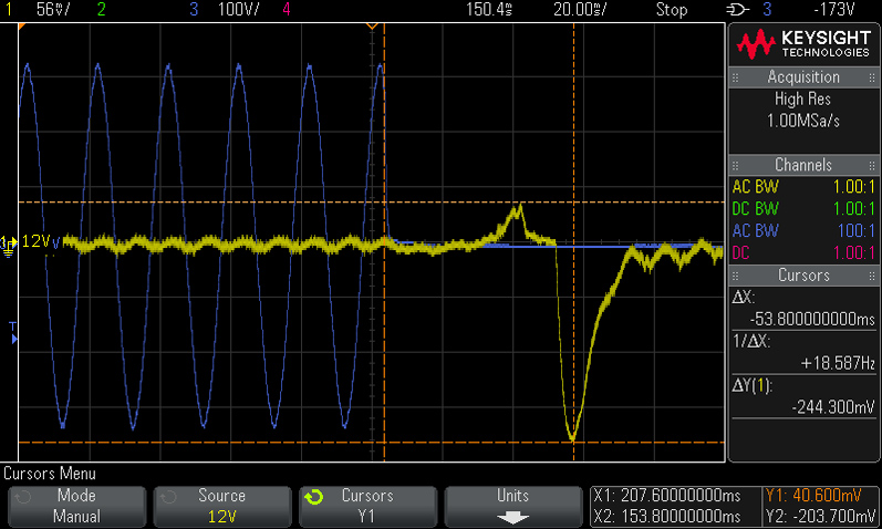
We noticed the first effect on the +12V rail's output 26.6 ms after removing power from the first module. This is very close to the power module's hold-up time, and we believe this is the moment the second module kicks in.
The peak of the voltage overshoot happens 39 ms after we remove power from the first module.
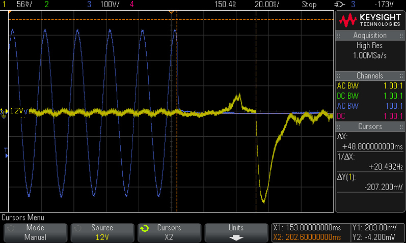
The voltage drop starts 48.8 ms after the power cut. Naturally, the second power module needs some time to adjust its operation to the transient load. The peak of the voltage drop is 53.8 ms after removing power to one of the modules.
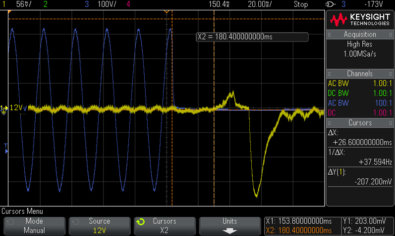
Here's the last scope screenshot. The transient recovery time is 21.4 ms, which is normal, and as you can see from the scope screenshot above, ripple at +12V slightly increases afterward because the module has to deliver 500 W on its own from now on out, instead of only half that amount, which was the case when both modules were operating.
Jul 10th, 2025 02:40 CDT
change timezone
Latest GPU Drivers
New Forum Posts
- Do you still use Antivirus software on your latest hardware? (75)
- Screen burn-in (21)
- TPU's Nostalgic Hardware Club (20493)
- 3DMARK "LEGENDARY" (326)
- Post Your TIMESPY, PCMARK10 & FIRESTRIKE SCORES! (2019) (321)
- 5070ti overclock...what are your settings? (47)
- 'NVIDIA App' not usable offline? (1)
- G-Sync Not Working in Borderless / Window Mode - Windows 11 (5)
- [GPU-Z Test Build] New Kernel Driver, Everyone: Please Test (78)
- Friend's monitor randomly loses signal (3)
Popular Reviews
- NZXT N9 X870E Review
- NVIDIA GeForce RTX 5050 8 GB Review
- Fractal Design Epoch RGB TG Review
- Corsair FRAME 5000D RS Review
- Fractal Design Scape Review - Debut Done Right
- AMD Ryzen 7 9800X3D Review - The Best Gaming Processor
- Sapphire Radeon RX 9060 XT Pulse OC 16 GB Review - An Excellent Choice
- Upcoming Hardware Launches 2025 (Updated May 2025)
- Sapphire Radeon RX 9070 XT Nitro+ Review - Beating NVIDIA
- PowerColor ALPHYN AM10 Review
TPU on YouTube
Controversial News Posts
- Intel's Core Ultra 7 265K and 265KF CPUs Dip Below $250 (288)
- Some Intel Nova Lake CPUs Rumored to Challenge AMD's 3D V-Cache in Desktop Gaming (140)
- NVIDIA Launches GeForce RTX 5050 for Desktops and Laptops, Starts at $249 (117)
- AMD Radeon RX 9070 XT Gains 9% Performance at 1440p with Latest Driver, Beats RTX 5070 Ti (116)
- NVIDIA GeForce RTX 5080 SUPER Could Feature 24 GB Memory, Increased Power Limits (115)
- Microsoft Partners with AMD for Next-gen Xbox Hardware (105)
- Intel "Nova Lake‑S" Series: Seven SKUs, Up to 52 Cores and 150 W TDP (100)
- NVIDIA DLSS Transformer Cuts VRAM Usage by 20% (97)