 50
50
Gigabyte UD1000GM PG5 1000 W Review - The First PCIe 5.0 PSU
Protection Features, Power Sequencing & EMC »Advanced Transient Response Tests
In these tests, we monitor the response of the PSU in two different scenarios. First, a transient load (15 A at +12V, 6 A at +5V, 6 A at +3.3V, and 0.5 A at 5VSB) is applied to the PSU for 20 ms while it is working at 20% load. In the second scenario, the PSU, while working at 50% load, is hit by the same transient load. In both tests, our oscilloscope measures the voltage drops caused by the transient load. All voltages should remain within the regulation limits defined by the ATX specification.In real-world usage, a PSU always operates under changing loads depending on whether the CPU or graphics card is busy. It is immensely important that the PSU keep its rails within limits defined by the ATX specification. Smaller deviations reduce the stress applied to system components.
We should note that the ATX specification requires capacitive loading during the transient tests. Still, in our methodology, we chose to apply the worst-case scenario with no extra capacitance on the rails. Although the ATX specification asks for this capacitance, your system—the mainboard and its other parts—may not provide it, which we have to keep in mind as well.
| Advanced Transient Response 20% - 50 Hz | ||||
|---|---|---|---|---|
| Voltage | Before | After | Change | Pass/Fail |
| 12V | 12.020V | 11.837V | 1.52% | Pass |
| 5V | 5.078V | 4.962V | 2.29% | Pass |
| 3.3V | 3.329V | 3.185V | 4.32% | Pass |
| 5VSB | 5.029V | 4.987V | 0.84% | Pass |
| Advanced Transient Response 50% - 50 Hz | ||||
|---|---|---|---|---|
| Voltage | Before | After | Change | Pass/Fail |
| 12V | 12.003V | 11.912V | 0.76% | Pass |
| 5V | 5.056V | 4.940V | 2.29% | Pass |
| 3.3V | 3.309V | 3.156V | 4.64% | Pass |
| 5VSB | 5.008V | 4.964V | 0.89% | Pass |
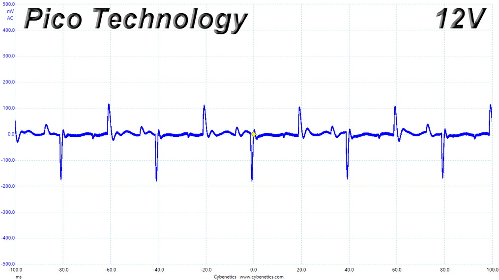
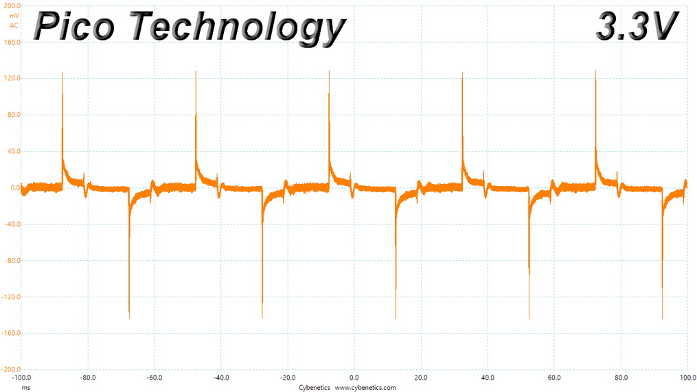
The normal transient response tests exhibit no issues. However, I would like to see the 3.3 V rail stay above 3.2 V.
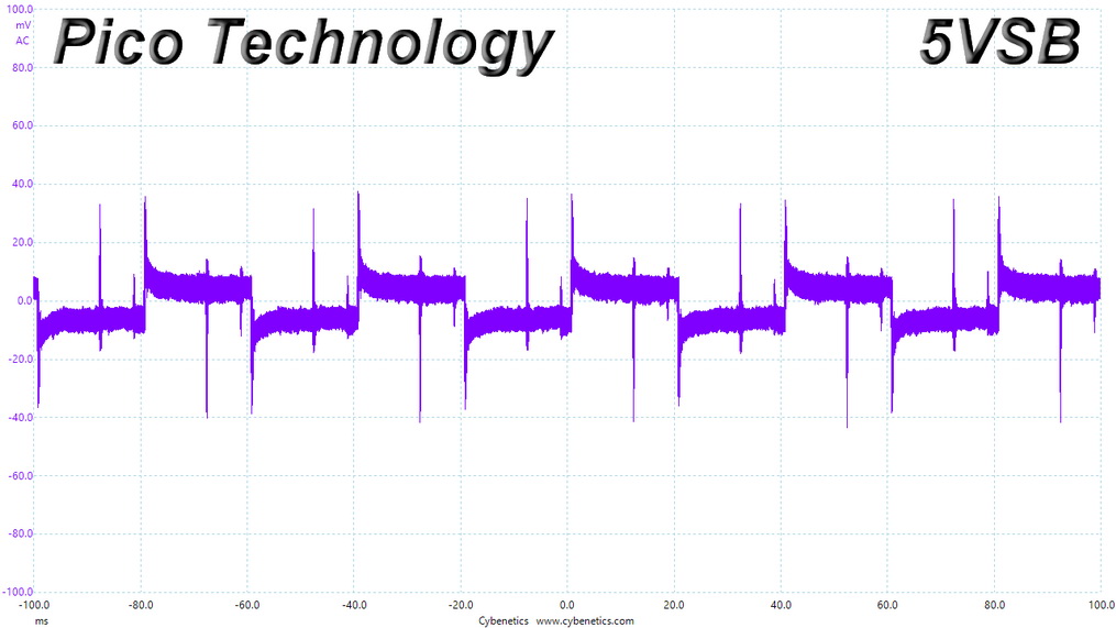
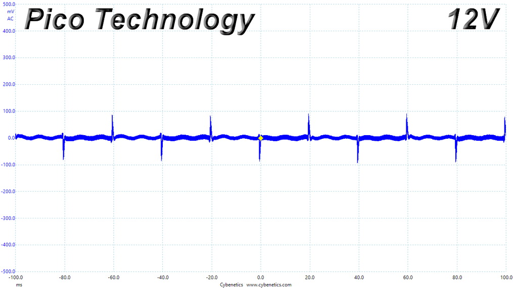
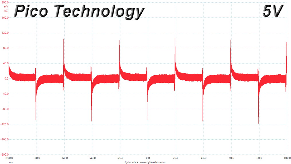
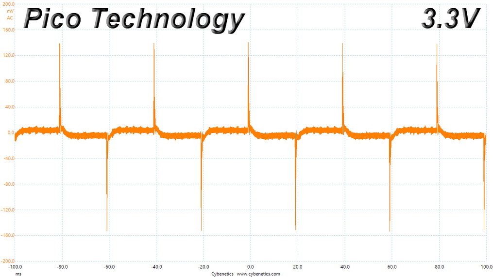
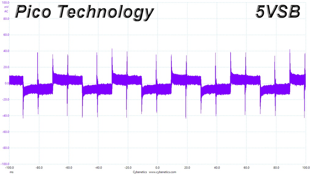
Below are the oscilloscope screenshots we took during Advanced Transient Response testing.
Transient Response at 20% Load

Transient Response at 50% Load
Advanced Transient Response Tests According to ATX v3.0
The ATX v3.0 specification this PSU claims to be compatible with requires a much tougher set of transient response tests, which are depicted below.Without Extra Capacitance
With Extra Capacitance
With the required capacitance of the ATX specification, the PSU passes the tests with 200% and 120% transient loads. There is a problem with 180% and 160%, where the transient load is applied for longer periods—1 ms and 10 ms respectively. At those values, the PSU shut down whenever I conducted the tests. This is an issue as according to ATX v3.0, the PSU should be able to handle these transient load scenarios.
Turn-On Transient Tests
We measure the response of the PSU in more straightforward scenarios of transient load—during the power-on phase of the PSU—in the next set of tests. In the first test, we turn the PSU off, dial the maximum current the 5VSB can output, and then switch on the PSU. In the second test, we dial the maximum load +12V can handle and start the PSU while the PSU is in standby mode. In the last test, while the PSU is completely switched off (we cut off power or switch the PSU off by flipping its on/off switch), we dial the maximum load the +12V rail can handle before switching the PSU on from the loader and restoring power. The ATX specification states that recorded spikes on all rails should not exceed 10% of their nominal values (e.g., +10% for +12V is 13.2 V and 5.5 V for +5V).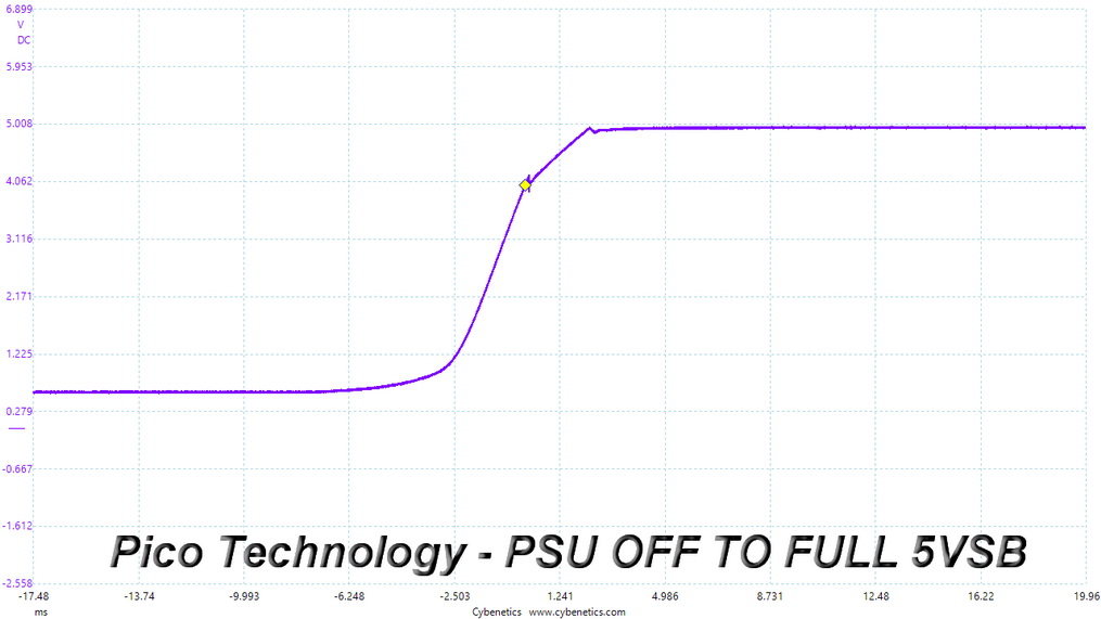
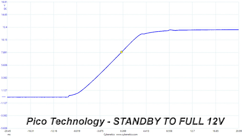
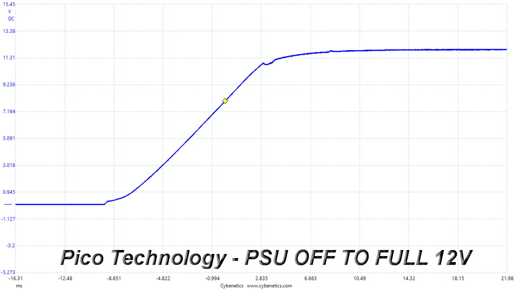
There is a tiny overshoot at 5VSB, which won't create any issues. The +12 V slopes are not straight, but you can't call them bad, either.
Inrush Current
Inrush current, or switch-on surge, refers to the maximum, instantaneous input current drawn by an electrical device when it is first turned on. If high enough, inrush current can cause the tripping of circuit breakers and fuses and may also damage switches, relays, and bridge rectifiers. As a result, the lower the inrush current of a PSU right as it is turned on, the better.
Inrush current is pretty high with 230 V input.
Leakage Current
We use a GW Instek GPT-9904 electrical safety tester to measure the leakage current. According to the IEC-60950-1 regulation, no power supply should exceed 3.5 mA of leakage current, which is low enough not to harm anyone touching the chassis. This test is performed at 110% of the rated input voltage.
While still considerably below the limit, leakage current is high compared to PSUs with similar specifications.
Jun 30th, 2025 17:51 CDT
change timezone
Latest GPU Drivers
New Forum Posts
- Can you guess Which game it is? (194)
- Help me choose the right PSU , Cooler Master vs Seasonic (53)
- HOW TO ADD NVMe M.2 SSD SUPPORT TO OLD MOTHERBOARDS WITH AWARD-Phoenix LEGACY SUPPORT? (2)
- Whats a fair asking price - MSI 4070 Super (4)
- HTPC Power Consumption Discussion, Upgrade vs Migration (18)
- RX 9000 series GPU Owners Club (1103)
- Will you buy a RTX 5090? (579)
- Rare GPUs / Unreleased GPUs (2111)
- Steam Deck Owners Clubhouse (530)
- Good time in the year to buy a new PC (4)
Popular Reviews
- Sapphire Radeon RX 9070 XT Nitro+ Review - Beating NVIDIA
- ASUS ROG Crosshair X870E Extreme Review
- Sapphire Radeon RX 9060 XT Pulse OC 16 GB Review - Samsung Memory Tested
- Lexar NQ780 4 TB Review
- AVerMedia CamStream 4K Review
- ASRock Phantom Gaming Z890 Riptide Wi-Fi Review
- AMD Ryzen 7 9800X3D Review - The Best Gaming Processor
- Upcoming Hardware Launches 2025 (Updated May 2025)
- Intel Core Ultra 7 265K Review
- NVIDIA GeForce RTX 5060 8 GB Review
TPU on YouTube
Controversial News Posts
- Intel's Core Ultra 7 265K and 265KF CPUs Dip Below $250 (288)
- NVIDIA Grabs Market Share, AMD Loses Ground, and Intel Disappears in Latest dGPU Update (204)
- Some Intel Nova Lake CPUs Rumored to Challenge AMD's 3D V-Cache in Desktop Gaming (140)
- Microsoft Partners with AMD for Next-gen Xbox Hardware (105)
- NVIDIA Launches GeForce RTX 5050 for Desktops and Laptops, Starts at $249 (104)
- Intel "Nova Lake‑S" Series: Seven SKUs, Up to 52 Cores and 150 W TDP (100)
- NVIDIA GeForce RTX 5080 SUPER Could Feature 24 GB Memory, Increased Power Limits (89)
- Reviewers Bemused by Restrictive Sampling of RX 9060 XT 8 GB Cards (88)