 3
3
LEPA MaxPlatinum Series 1700 W Review
Ripple Measurements »Advanced Transient Response Tests
In these tests, we monitor the response of the PSU in two different scenarios. First, a transient load (10 A at +12V, 5 A at 5V, 5 A at 3.3V, and 0.5 A at 5VSB) is applied to the PSU for 200 ms while the latter is working at 20% load. In the second scenario, the PSU, while working at 50% load, is hit by the same transient load. In both tests, we measure the voltage drops the transient load causes using our oscilloscope. The voltages should remain within the regulation limits defined by the ATX specification. We must stress here that these tests are crucial since they simulate transient loads a PSU is very likely to handle (e.g., booting a RAID array, an instant 100% load of CPU/VGAs, etc.). We call these tests "Advanced Transient Response Tests", and they are designed to be very tough to master, especially for a PSU with a capacity below 500 W.| Advanced Transient Response 20% | ||||
|---|---|---|---|---|
| Voltage | Before | After | Change | Pass/Fail |
| 12 V | 12.205V | 12.155V | 0.41% | Pass |
| 5 V | 5.084V | 4.987V | 1.91% | Pass |
| 3.3 V | 3.375V | 3.258V | 3.47% | Pass |
| 5VSB | 5.051V | 5.018V | 0.65% | Pass |
| Advanced Transient Response 50% | ||||
|---|---|---|---|---|
| Voltage | Before | After | Change | Pass/Fail |
| 12 V | 12.081V | 12.021V | 0.50% | Pass |
| 5 V | 5.062V | 4.971V | 1.80% | Pass |
| 3.3 V | 3.354V | 3.234V | 3.58% | Pass |
| 5VSB | 5.013V | 4.971V | 0.84% | Pass |
Voltage deviations on +12V were low in both test, which is as it should be for such a high-capacity PSU. The three other rails performance pretty well, though we would like to see the 3.3V rail stay within 3%.
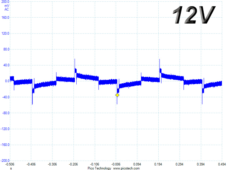
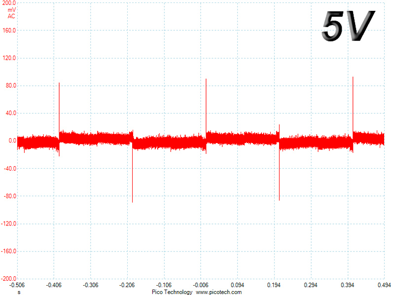
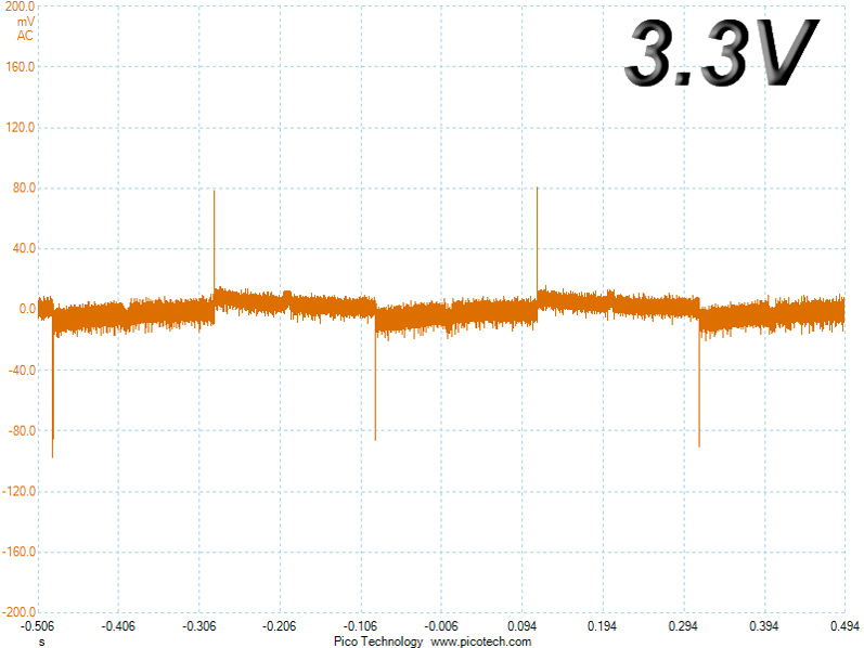
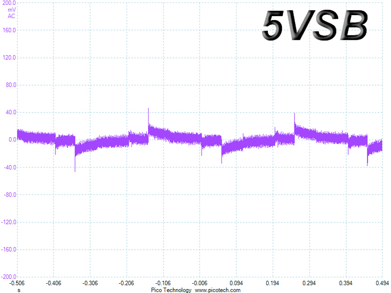
Below are the oscilloscope screenshots we took during Advanced Transient Response testing.
Transient Response at 20% Load
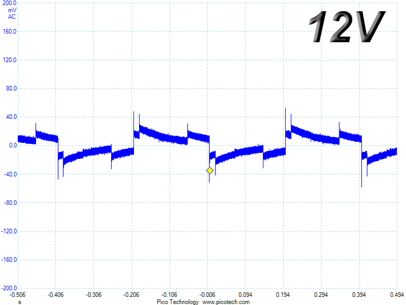
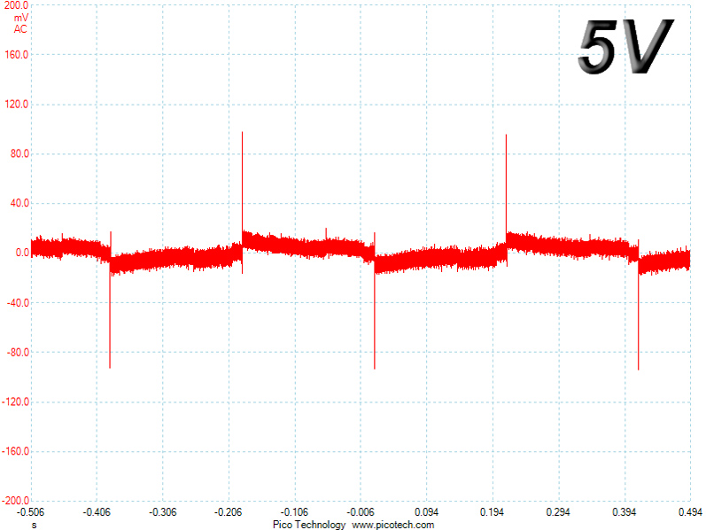
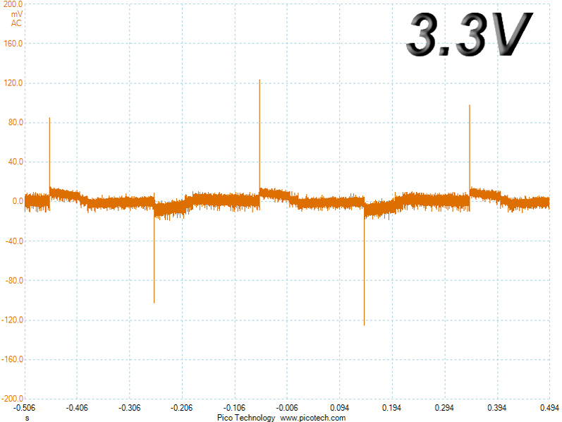
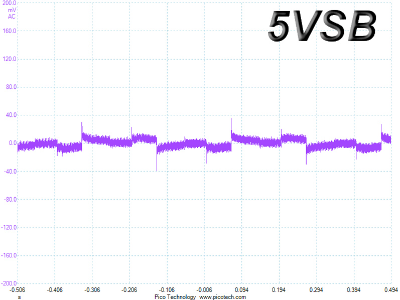
Transient Response at 50% Load
Turn-On Transient Tests
We measure the response of the PSU in simpler scenarios of transient load—during the power-on phase of the PSU—in the next set of tests. In the first test, we turn the PSU off, dial the maximum current the 5VSB can output, and then switch on the PSU. In the second test, we dial the maximum load +12V can handle and start the PSU while the PSU is in standby mode. In the last test, while the PSU is completely switched off (we cut off power or switch the PSU off by flipping its on/off switch), we dial the maximum load the +12V rail can handle before switching the PSU on from the loader and restoring power. The ATX specification states that recorded spikes on all rails should not exceed 10% of their nominal values (e.g., +10% for 12V is 13.2V and 5.5V for 5V).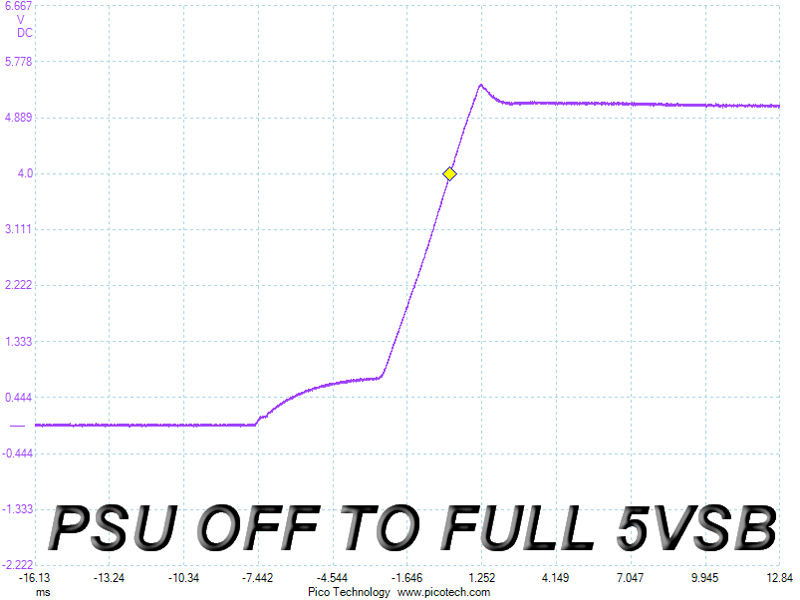
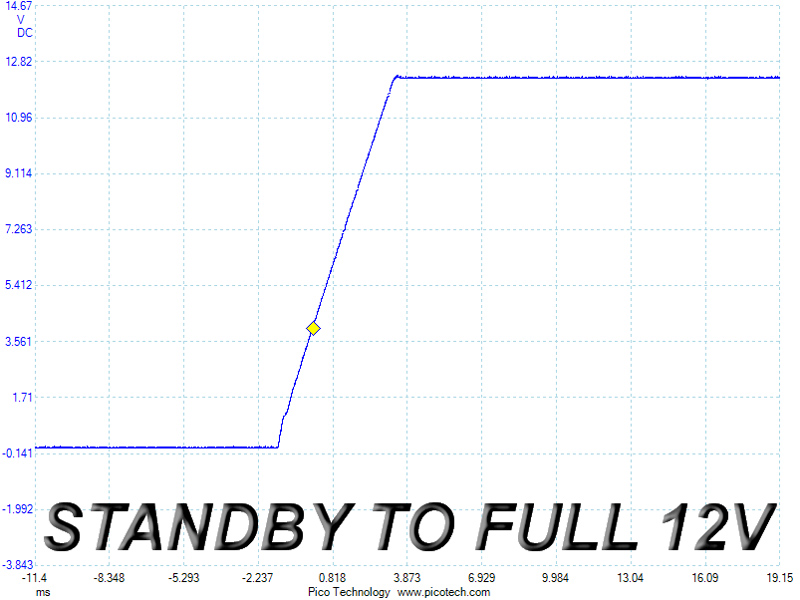
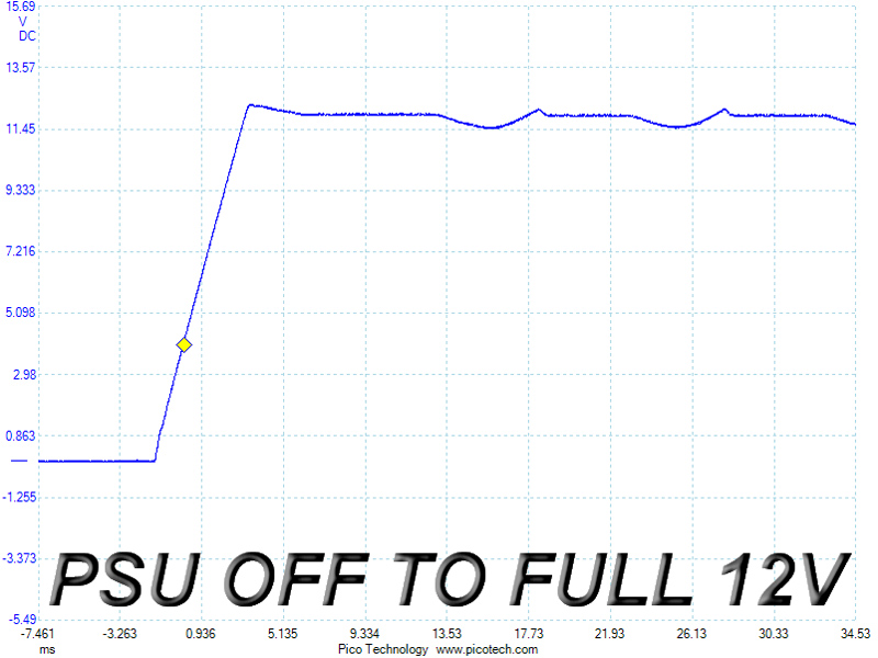
We measured a large voltage overshoot of 5.42 V at 5VSB, which is pretty close to the limit. The result was just perfect in our second test, and there were no voltage overshoots in the last test, but the rail took a very long time to settle down to its nominal voltage.
Feb 19th, 2025 15:49 EST
change timezone
Latest GPU Drivers
New Forum Posts
- RTX 5090 ridiculous price! (170)
- TPU's Nostalgic Hardware Club (19961)
- VRAM do you recommend for 4K gaming nowadays? (10)
- ASRock PHANTOM GAMING X870E Nova WiFi opinions (9)
- TECHPOWERUP HWBOT Contest with Cash Prizes (79)
- Issues with clock speed not increasing (26)
- Seasonic Prime Gold SSR-1300GD PSU enough for RTX 5090? (15)
- Lowering idle power on Zen 4? (93)
- Post your Speedometer 3.0 Score (112)
- It's happening again, melting 12v high pwr connectors (790)
Popular Reviews
- MSI GeForce RTX 5070 Ti Ventus 3X OC Review - Beating RX 7900 XTX
- Gigabyte GeForce RTX 5090 Gaming OC Review
- Galax GeForce RTX 5070 Ti 1-Click OC White Review
- Ducky One X Inductive Keyboard Review
- AMD Ryzen 7 9800X3D Review - The Best Gaming Processor
- WD Black SN7100 2 TB Review - The New Best SSD
- AVerMedia X'Tra Go GC515 Review
- NVIDIA GeForce RTX 5080 Founders Edition Review
- Kingdom Come Deliverance II Performance Benchmark Review - 35 GPUs Tested
- MSI MAG Z890 Tomahawk Wi-Fi Review
Controversial News Posts
- AMD Radeon 9070 XT Rumored to Outpace RTX 5070 Ti by Almost 15% (301)
- AMD is Taking Time with Radeon RX 9000 to Optimize Software and FSR 4 (256)
- AMD Plans Aggressive Price Competition with Radeon RX 9000 Series (245)
- Edward Snowden Lashes Out at NVIDIA Over GeForce RTX 50 Pricing And Value (241)
- AMD Denies Radeon RX 9070 XT $899 USD Starting Price Point Rumors (239)
- AMD Radeon RX 9070 and 9070 XT Listed On Amazon - One Buyer Snags a Unit (238)
- New Leak Reveals NVIDIA RTX 5080 Is Slower Than RTX 4090 (215)
- AMD's Radeon RX 9070 Launch Faces Pricing Hurdles (175)