 1
1
Mistel MD600 Barocco RGB Keyboard Review
Driver & Performance »Disassembly
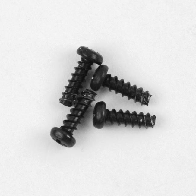
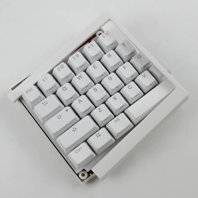
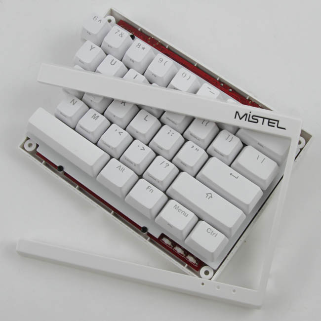
Given the Mistel MD600 Barocco is a split keyboard, it is only fair that each piece of the keyboard gets disassembled separately to see what makes these tick. Beginning with the left piece, there are four Phillips head screws on the back that are easily removed, which then helps dislodge the top plastic piece of the case. With the split nature of the keyboard, this piece is quite thin and has an exposed side as well. We can see that the case is made out of ABS plastic, and four more screws are now visible on the front.
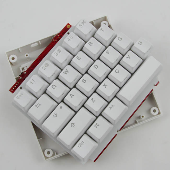
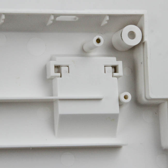
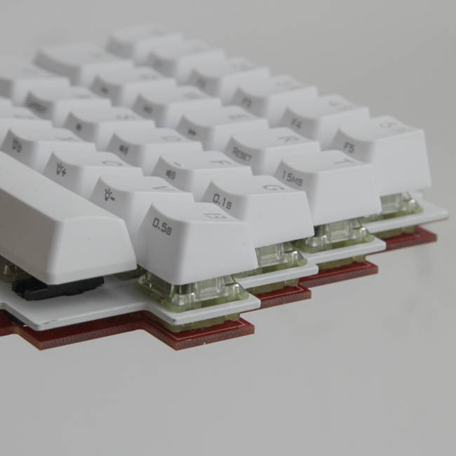
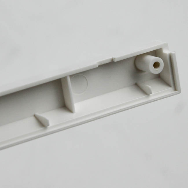
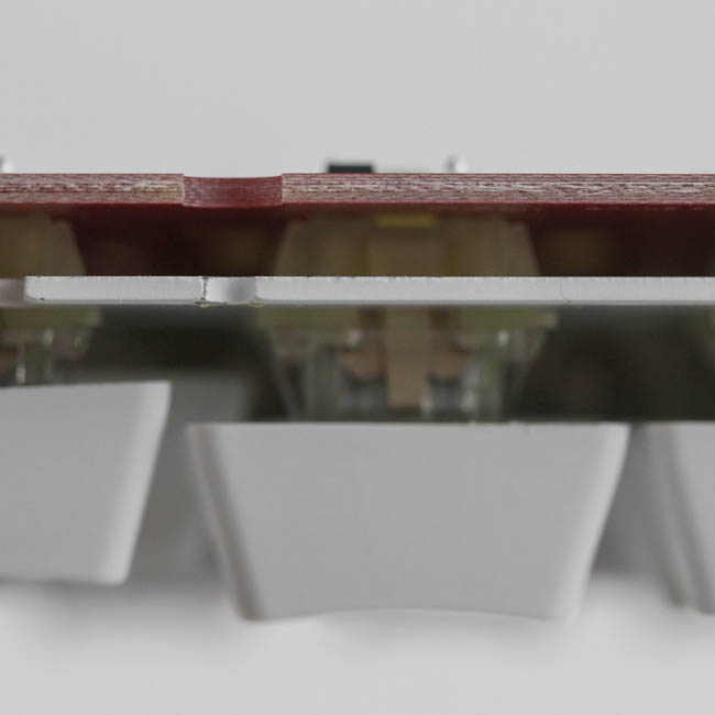
This next set of four screws keeps the plate/PCB in the bottom case panel piece, and with those removed, you can separate the two easily. Note that the I/O ports are level with the case, so it is best to remove the case by moving it upwards and away. We can now get a better look at the substantial size of the feet relative to the rest of the body, and also better appreciate the sharp angles in the cutout on the PCB and stainless steel plate. The PCB itself is a matte red in color and finish, and the switches are soldered in place through the plate for more structural integrity.
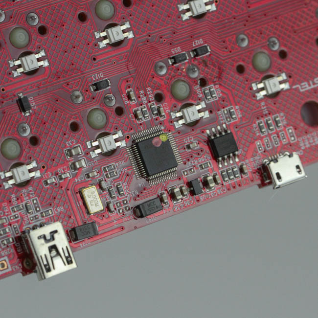
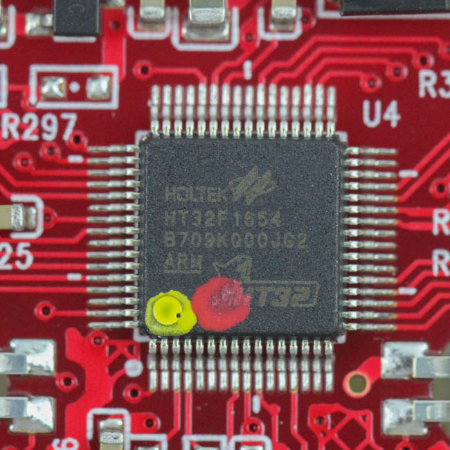
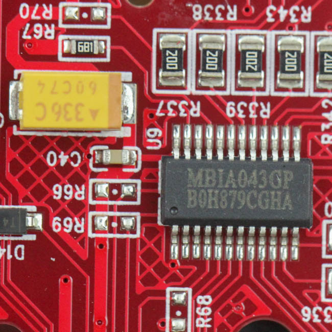
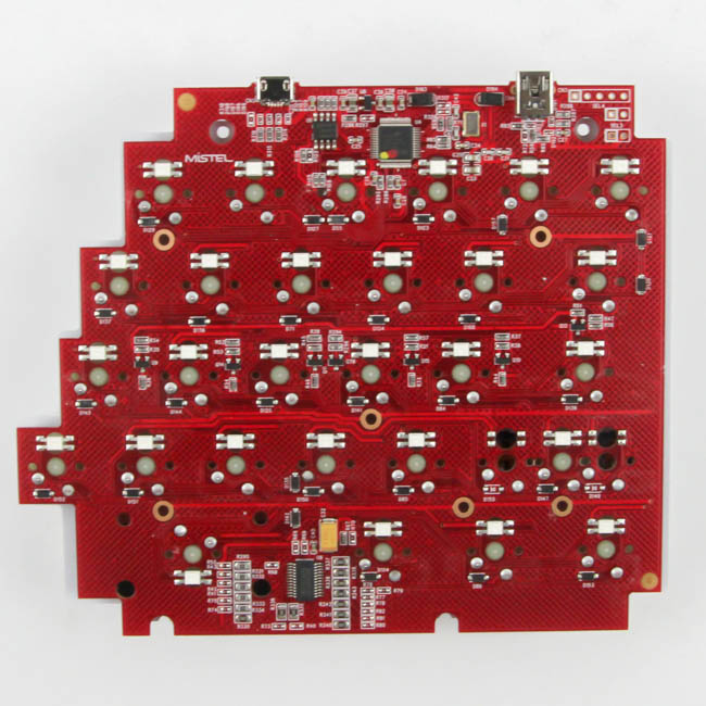
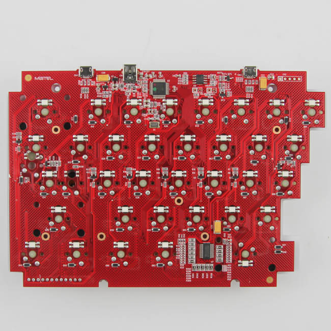
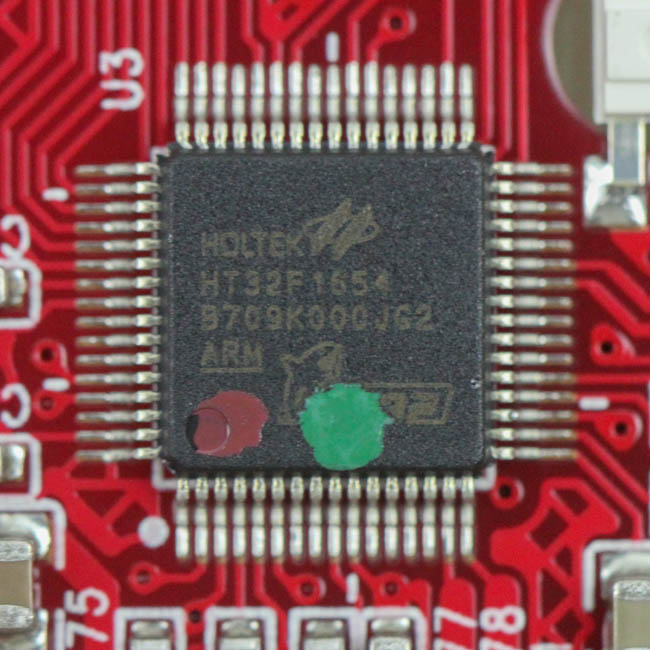
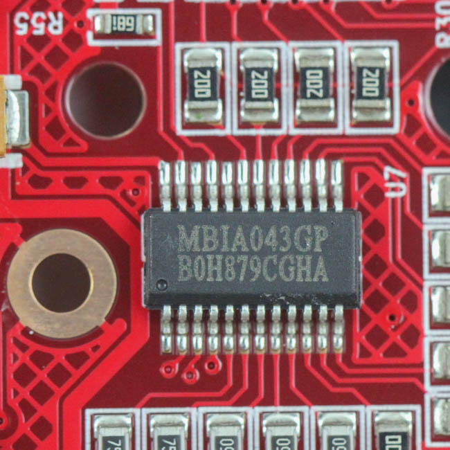
Solder quality is excellent with everything likely machine assembled to keep things tidy, especially on this unique PCB layout. The two ports are on one side, alongside some capacitors strewn across the I/O and the controller section. Powering the left piece of the MD600 Barocco is a Holtek HT32F1654 32-bit Arm® Cortex®-M3 microcontroller running at a frequency up to 72 MHz with a flash accelerator with up to 64 KB of onboard flash memory and 16 KB of SRAM. There is also a dedicated Macroblock MBIA043GP LED driver we have seen used before in other RGB-backlit keyboards to good effect. As per usual, all the components are soldered on to a multi-layer PCB.
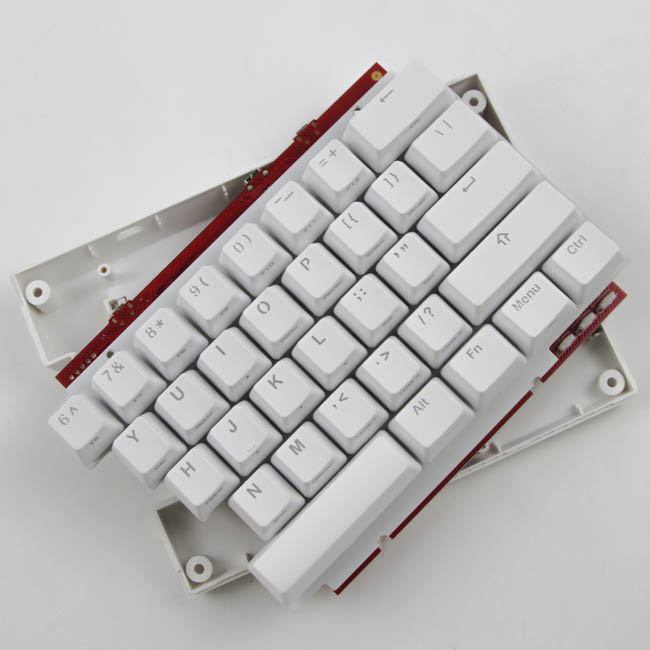
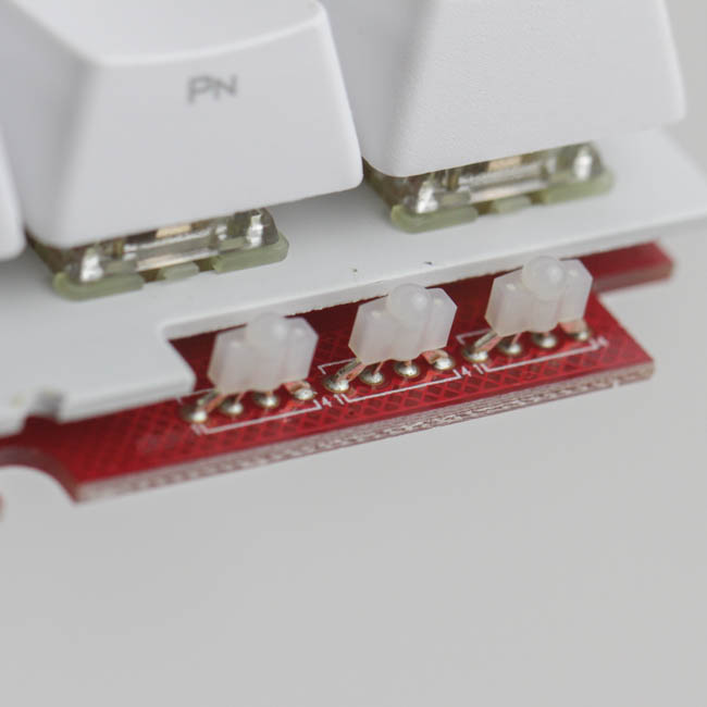
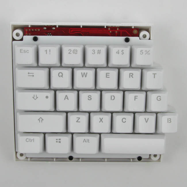
The right side of the keyboard is larger, but otherwise identical as far as disassembly goes. Four screws are again on the back to help remove the top panel piece, which also exposes the three LEDs in the bottom-right corner that act as indicator LEDs for the keyboard. There are four more screws accessible on the front, which in turn helps separate the plate/PCB from the bottom-panel piece. The PCB is very similar to the one on the left side, with another Holtek HT32F1654 MCU and a Macroblock MBIA043GP LED driver. There are three ports, as we saw before, and everything is soldered on to another multi-layered PCB.
Before we move on, be advised that disassembly will void the warranty and that TechPowerUp is not liable for any damages incurred if you decided to go ahead and do so anyway.
Jul 12th, 2025 11:23 CDT
change timezone
Latest GPU Drivers
New Forum Posts
- CPU Scaling with 9070 XT / 5070 (1)
- No offense, here are some things that bother me about your understanding of fans. (47)
- TPU's Nostalgic Hardware Club (20496)
- Best motherboards for XP gaming (105)
- Swapping existing router w/ a replacement; any issues? (15)
- Stupid buggy POS Realtek WiFi RTL8852BE (13)
- 6.15.6 MITIGATION_TSA // Intel CPU Users can skip this topic (0)
- 14700t vs 14600k for gaming system (2)
- New build airflow question (6)
- Tired of consumer grade networking hardware, need suggestions… (2)
Popular Reviews
- Fractal Design Epoch RGB TG Review
- Lexar NM1090 Pro 4 TB Review
- Corsair FRAME 5000D RS Review
- NVIDIA GeForce RTX 5050 8 GB Review
- NZXT N9 X870E Review
- Our Visit to the Hunter Super Computer
- Sapphire Radeon RX 9060 XT Pulse OC 16 GB Review - An Excellent Choice
- AMD Ryzen 7 9800X3D Review - The Best Gaming Processor
- Upcoming Hardware Launches 2025 (Updated May 2025)
- Chieftec Iceberg 360 Review
TPU on YouTube
Controversial News Posts
- Intel's Core Ultra 7 265K and 265KF CPUs Dip Below $250 (288)
- Some Intel Nova Lake CPUs Rumored to Challenge AMD's 3D V-Cache in Desktop Gaming (140)
- AMD Radeon RX 9070 XT Gains 9% Performance at 1440p with Latest Driver, Beats RTX 5070 Ti (131)
- NVIDIA Launches GeForce RTX 5050 for Desktops and Laptops, Starts at $249 (119)
- NVIDIA GeForce RTX 5080 SUPER Could Feature 24 GB Memory, Increased Power Limits (115)
- Microsoft Partners with AMD for Next-gen Xbox Hardware (105)
- Intel "Nova Lake‑S" Series: Seven SKUs, Up to 52 Cores and 150 W TDP (100)
- NVIDIA DLSS Transformer Cuts VRAM Usage by 20% (97)