 24
24
Thermaltake Toughpower 1500 W Review
Voltage Regulation & Efficiency »A Look Inside
Before reading this page we strongly suggest to take a look at this article, which will help you understand the internal components of a PSU much better.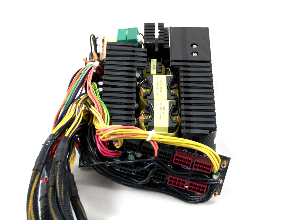
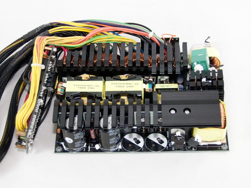
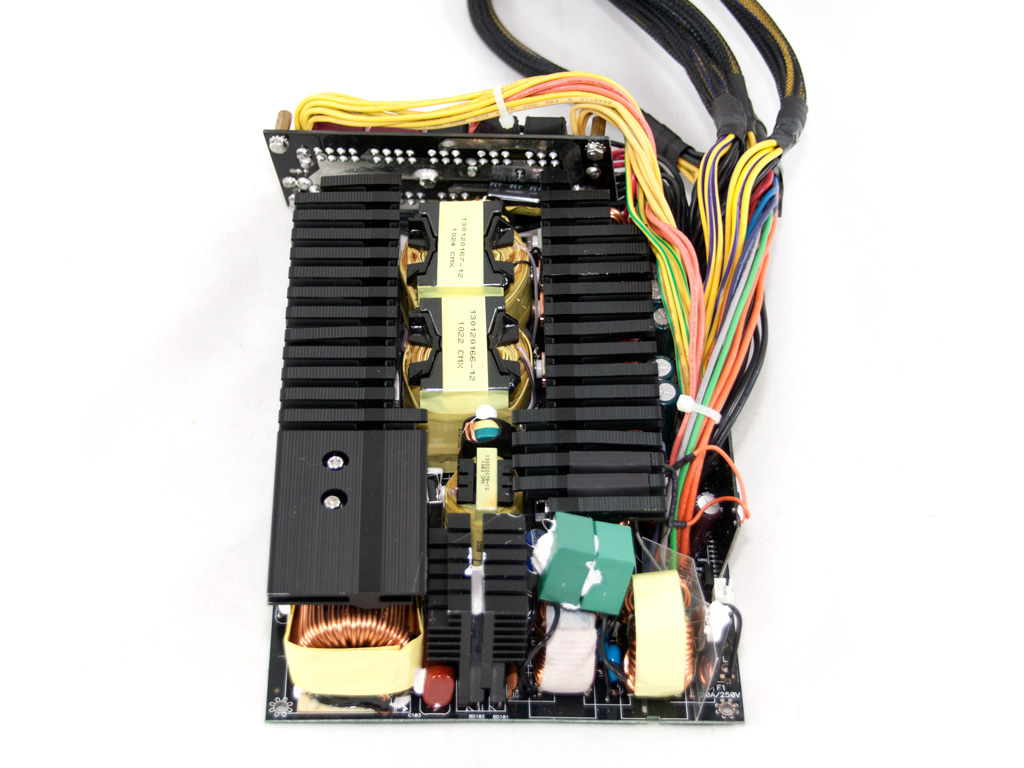
The OEM of the PSU is Enhance Electronics, a respectable manufacturer which also lent this platform to Silverstone for the Strider 1500W (ST1500). As you can see the main PCB is overcrowed with components and the heatsinks are huge with large fins. To give you a better view of the internals we removed half of the APFC caps. This time we didn't want to fight with the enormous secondary heatsink but soon enough, thanks to a new desoldering tool that will be added to our equipment really soon, desoldering of such beast heatsinks will be a breeze.
The transient filtering stage as usual starts right at the AC receptacle with two pairs of X and Y caps. On the main PCB we find more transient filtering components namely two large CM chokes, an MOV and two more pairs of X and Y caps.
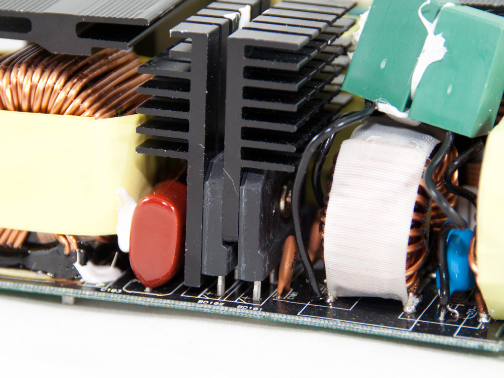
The bridge rectifiers are bolted on dedicated heatsinks. Their model number is LVB2560 and each can handle 25A so in total we have 50A! Talk about overspec here.
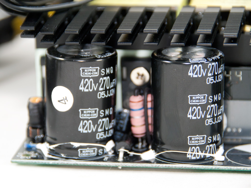
In the APFC three SPW47N60C3 mosfets chop up the fully rectified signal. The boost diode is hidden by another diode and right next to it a thermistor, for inrush current protection. The four parallel hold up caps are provided by Nippon Chemi-Con and have 270μF each and 1080μF total. All are rated at 105°C and can handle up to 420V, so they have a 40V safety margin from the 380V DC bus which is sufficient. Hiding behind the caps is a vertical board which most likely houses the PFC/PWM controller.
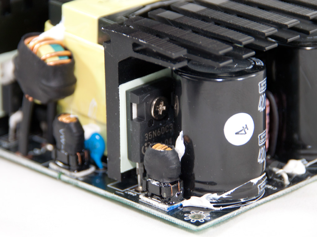
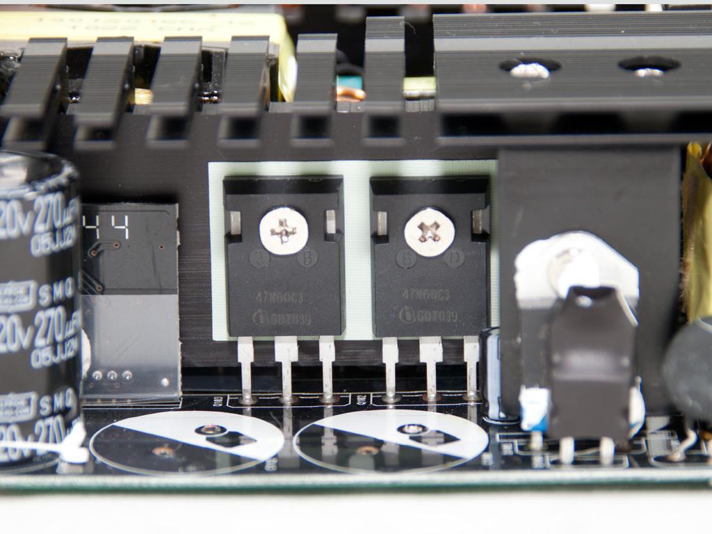
As main switches we find two SPW35N60C3 fets in the traditional double-forward topology. Each of them has 0.1Ω Rds(On) at worst case. For those who are not familiar with the aforementioned characteristic let's provide some explanations. A mosfet is actually a switch that has the ability to switch really fast (KHz range) between On and Off states. However it can't switch instantly even if the switching speed is very high. There will always be a period in which the mosfet will be between the On and Off state (also called linear mode) so it will have some resistance. The higher this resistance is, the higher the heat dissipation on the mosfet, causing huge stress on it and on top of that efficiency drops since heat means energy loss. Ending what you should remember from all above: the smaller the Rds(on) value of a mosfet the better, since less energy is lost meaning efficiency is retained at high levels.
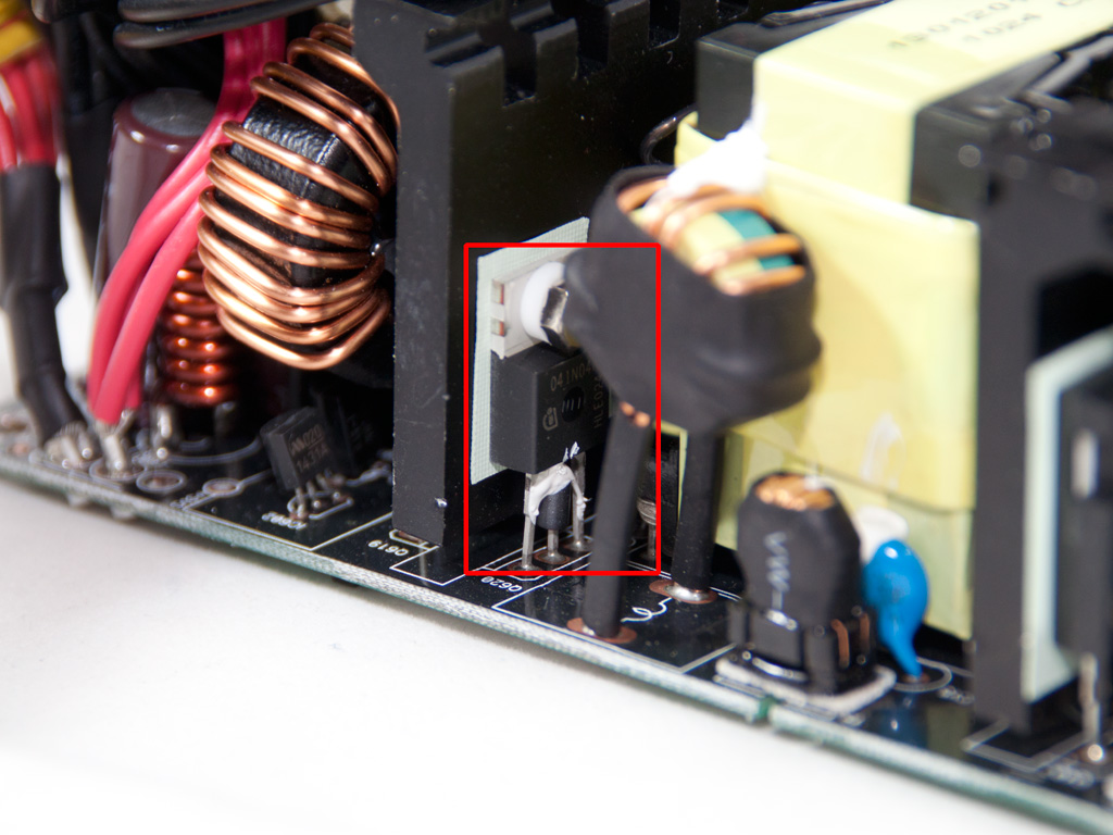
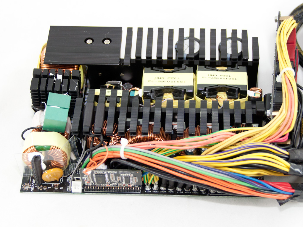
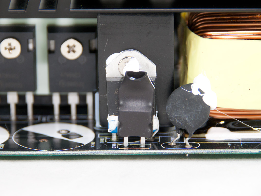
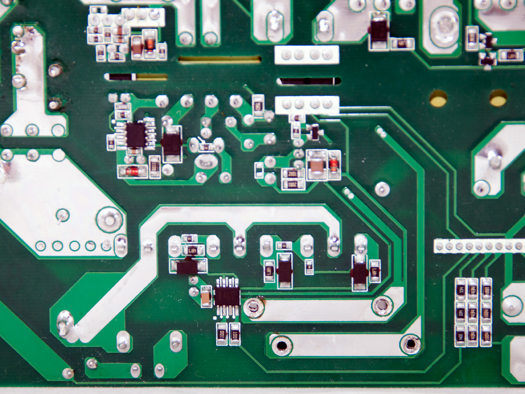
Between the primary and the secondary heatsinks we find two large parallel transformers. Apparently there was no space for a single huge one so the only option was to use two smaller transformers. In the secondary synchronous design is used (with one exception: one diode is used for 3.3V) so +12V handle six IRFB3206 mosfets in two groups of three, 5V are generated by two IPP041N04N fets while 3.3V regulate a diode and a fet (unfortunately we couldn't make out their exact model numbers without serious desoldering). On the side of the secondary heatsink resides the 5VSB regulator, an MBR1660 which can handle up to 16A of power.

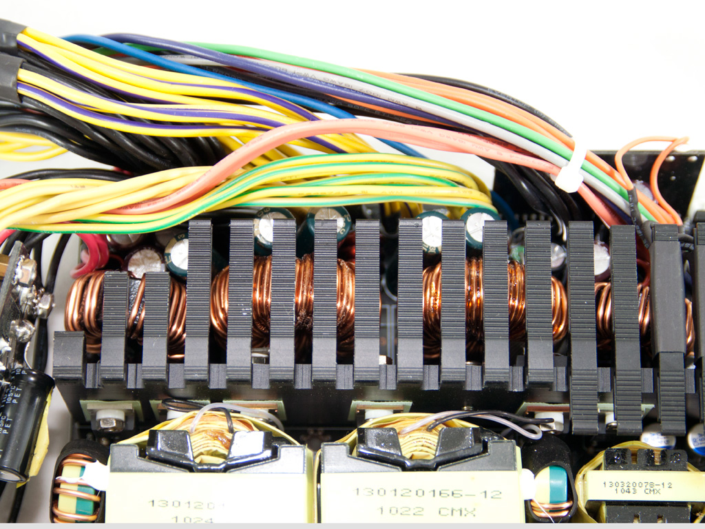
There are four toroidal chokes present in the secondary side. The two in the center are for +12V and the rest for 5V and 3.3V. Like the two transformers scenario, there was no space for a huge +12V choke so two smaller ones were used instead. Also since there are two chokes and two groups with three mosfets each, most likely we have phase-shifted regulation at +12V.
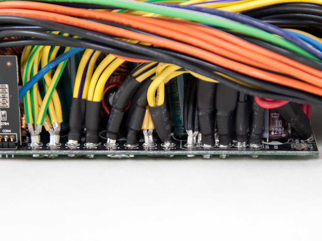
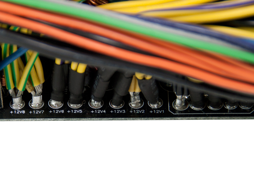
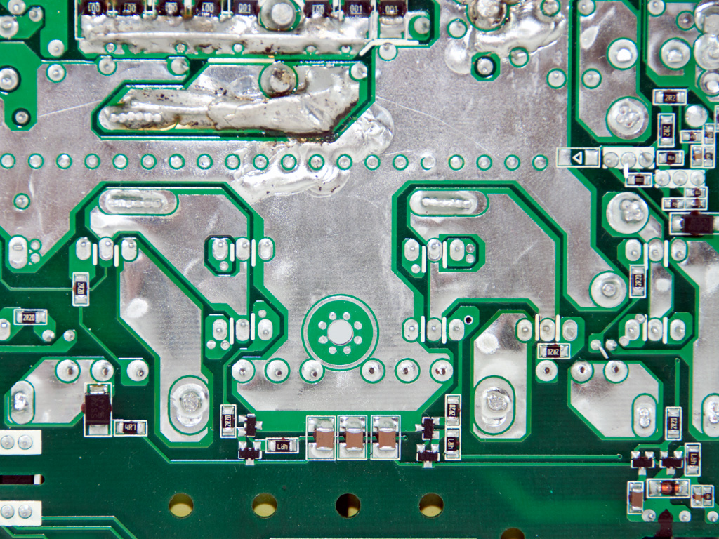
The filtering caps used in the secondary side are provided mostly by Teapo while there are few Chemi-Cons and Rubycons. All are rated at 105°C. While there are eight +12V islands on the solder side of the main PCB the +12V virtual rails are shorted in pairs with rather sloppy joints. So the eight +12V rails on the main PCB actually have become four.
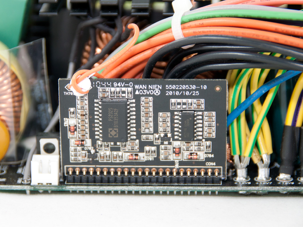
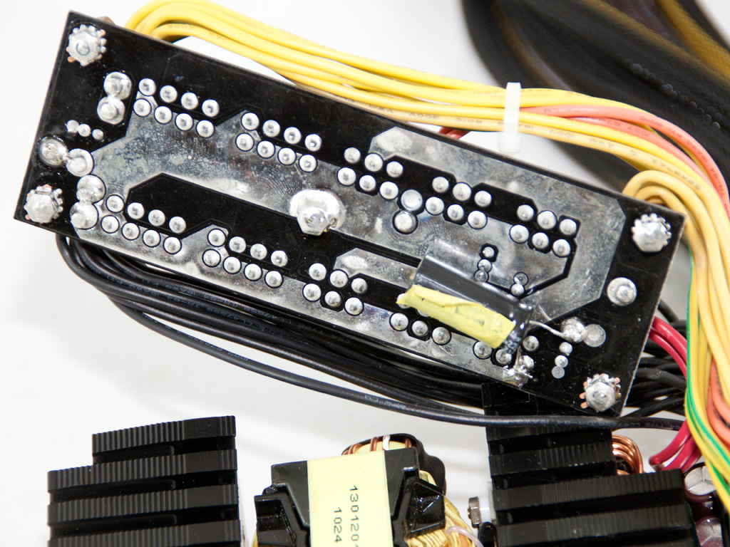
In order to provide OCP for eight +12V virtual rails, the actual number that this plarform has, there are two protection ICs, a PS232S and a WT7518. Each one supports up to four +12V channels and both are soldered on a vertical PCB in the secondary side.
On the front of the modular panel there are four, very small, SUNCON caps while on the solder side we find a lonely Rubycon cap. With a little research on the net we found out that SUNELEC, the maker of SUNCON caps, bought Sanyo's electrolytic caps production and also they used to make SANYO caps before the sell off. So these must be good quality caps.
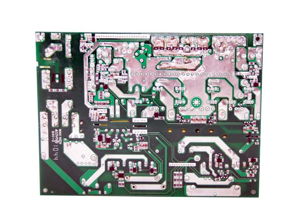
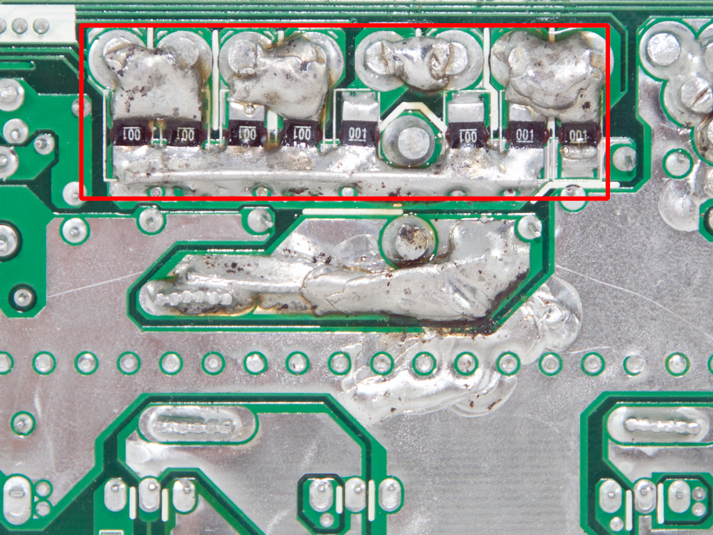
Soldering quality on the main PCB is quite good although there are areas with handmade, sloppy, solder joints.
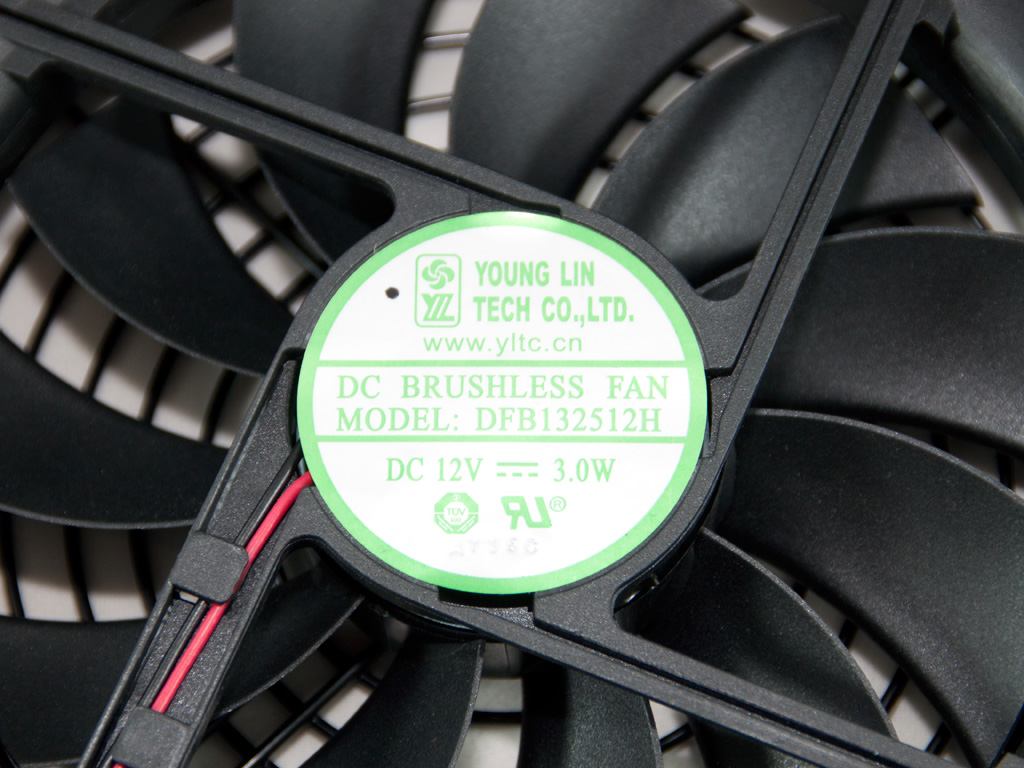
The cooling fan is provided by Young Lin Tech and its model number is DFB132512H (12V, 3W). It works very efficiently and without making much noise.
Jul 10th, 2025 02:46 CDT
change timezone
Latest GPU Drivers
New Forum Posts
- Do you still use Antivirus software on your latest hardware? (75)
- Screen burn-in (21)
- TPU's Nostalgic Hardware Club (20493)
- 3DMARK "LEGENDARY" (326)
- Post Your TIMESPY, PCMARK10 & FIRESTRIKE SCORES! (2019) (321)
- 5070ti overclock...what are your settings? (47)
- 'NVIDIA App' not usable offline? (1)
- G-Sync Not Working in Borderless / Window Mode - Windows 11 (5)
- [GPU-Z Test Build] New Kernel Driver, Everyone: Please Test (78)
- Friend's monitor randomly loses signal (3)
Popular Reviews
- NZXT N9 X870E Review
- NVIDIA GeForce RTX 5050 8 GB Review
- Fractal Design Epoch RGB TG Review
- Corsair FRAME 5000D RS Review
- Fractal Design Scape Review - Debut Done Right
- AMD Ryzen 7 9800X3D Review - The Best Gaming Processor
- Sapphire Radeon RX 9060 XT Pulse OC 16 GB Review - An Excellent Choice
- Upcoming Hardware Launches 2025 (Updated May 2025)
- Sapphire Radeon RX 9070 XT Nitro+ Review - Beating NVIDIA
- PowerColor ALPHYN AM10 Review
TPU on YouTube
Controversial News Posts
- Intel's Core Ultra 7 265K and 265KF CPUs Dip Below $250 (288)
- Some Intel Nova Lake CPUs Rumored to Challenge AMD's 3D V-Cache in Desktop Gaming (140)
- NVIDIA Launches GeForce RTX 5050 for Desktops and Laptops, Starts at $249 (117)
- AMD Radeon RX 9070 XT Gains 9% Performance at 1440p with Latest Driver, Beats RTX 5070 Ti (116)
- NVIDIA GeForce RTX 5080 SUPER Could Feature 24 GB Memory, Increased Power Limits (115)
- Microsoft Partners with AMD for Next-gen Xbox Hardware (105)
- Intel "Nova Lake‑S" Series: Seven SKUs, Up to 52 Cores and 150 W TDP (100)
- NVIDIA DLSS Transformer Cuts VRAM Usage by 20% (97)