 11
11
Thermaltake Xaser VI Case Review
Value & Conclusion »Installation

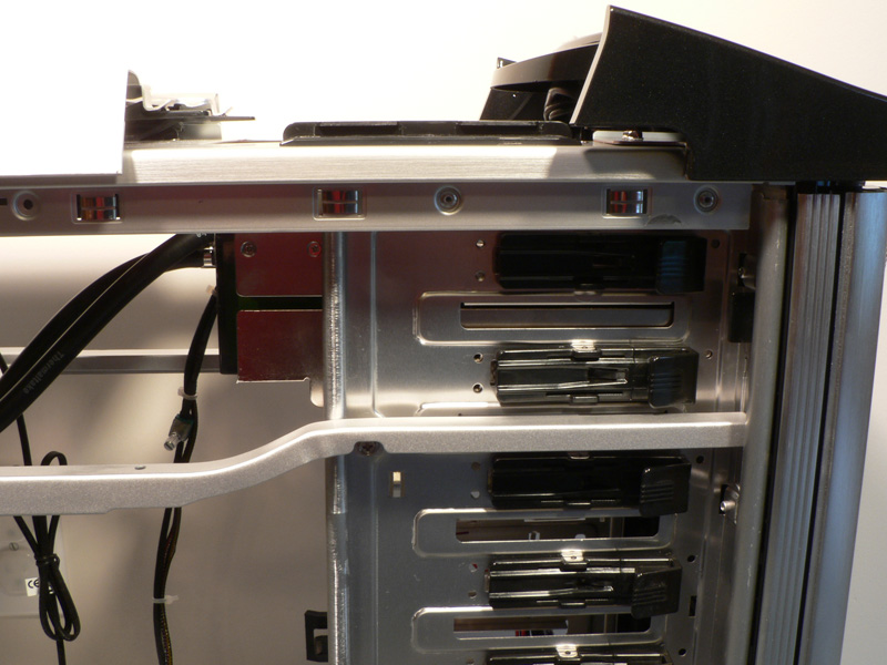
The Thermaltake Xaser VI is available in a standard air-cooled version and a liquid-cooled version. The second is basically the same as the first but with a slightly different version of the Bigwater 760i watercooling system installed. Since I happened to have one on hand, I thought it would be nice to show you what it would be like. With the top two bay covers removed, the entire unit slid easily into place. I removed the tray on top of the case by removing the four screws on the tray, as well as the two silver screws for the support bracket. I left the other bracket in the case, which is slightly visible over the fan. By removing the tray, the user would have access to the reservoir for occasional filling, and the radiator fan would have plenty of fresh cool air through the mesh on top.
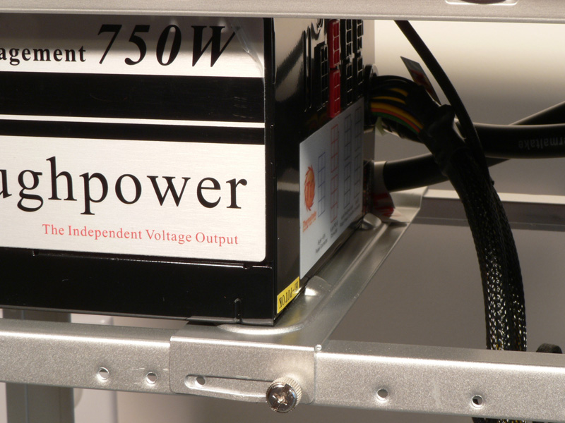
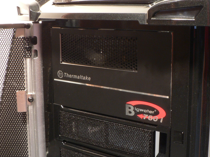
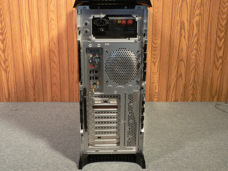
By looking at the rear of the case at the PSU bracket, it may seem like the bracket can be removed and attached to the power supply, then installed together. The bracket is removable, however it should not be removed to mount the PSU. The bracket is too big to fit between the support rails along the power supply area. But by adding the bracket Thermaltake added strength to this area, since the two layers are screwed together. To support the front of the PSU the bridge needs to slide under the power supply until the two small tabs rest against the front edge. The slots in the sides of the bridge make it very adjustable, and two thumbscrews are used to tighten the bridge when in place.
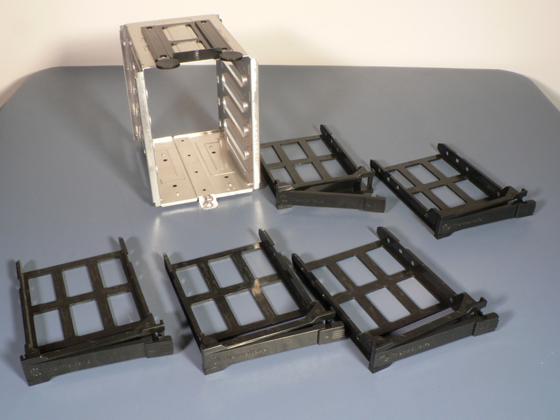
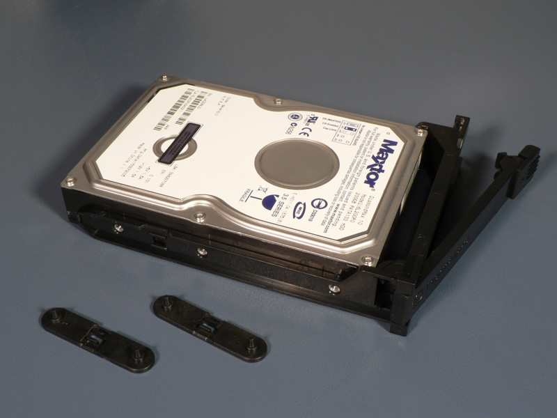
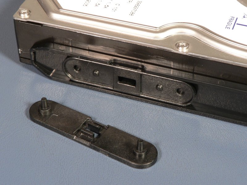
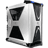
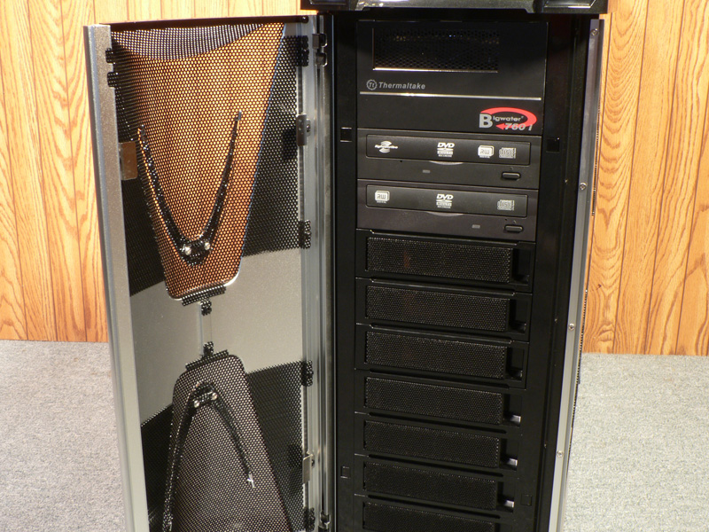
To install hard drives into the system, remove any needed drawers from their cages and get two black clips for each drive. Put the drive into the drawer (with the cable end on the open side) and simply snap a clip into the screw holes on each side of the drive through the openings of the drawer.
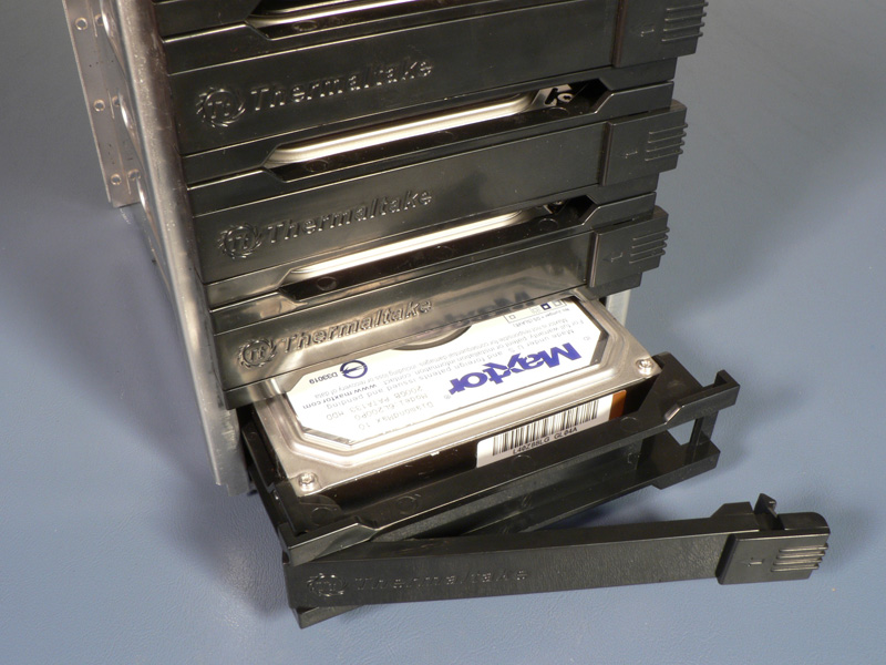
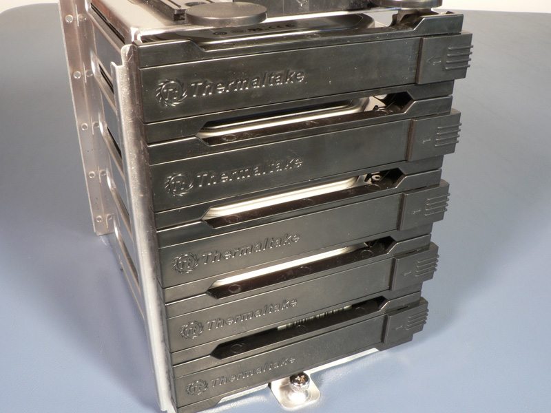
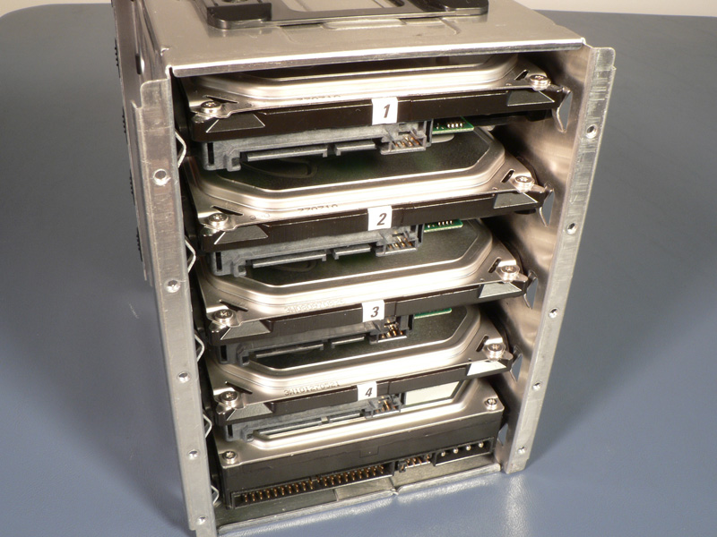
Each drawer should then be slid back into the cage. The exposed side of the cage looks nearly the same regardless of how many drives are installed, so it does not look like there is something missing if not all of the drawers are used. From the back side, all the cables can be attached to this end, avoiding cable clutter.
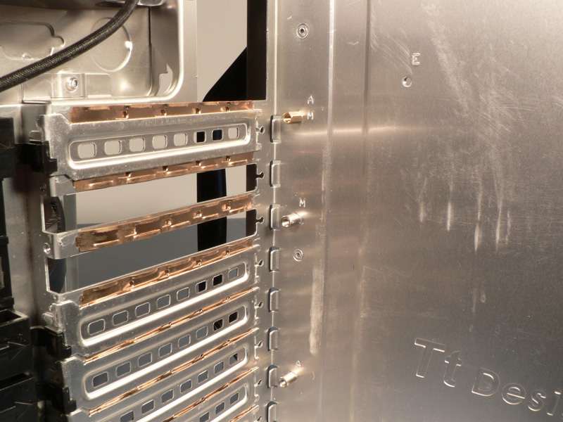
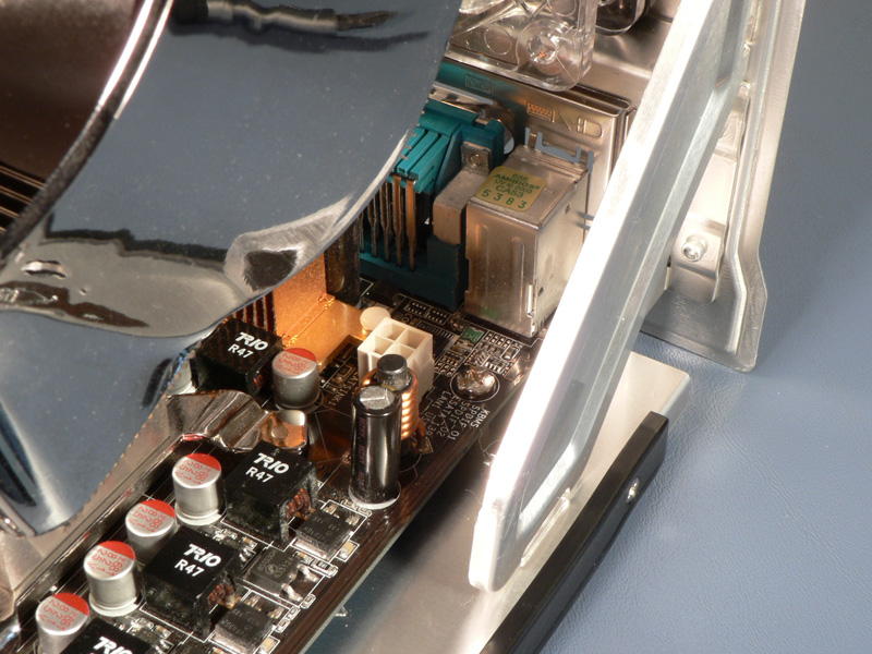
With the motherboard tray removed from the system it was time to install the board. I removed two of the PCI slot covers to make way for the video card, and noticed the brass springs-clips in place. These provide some extra tension and help reduce rattles. However, about this time I noticed the two silver standoffs that are permanently attached to the motherboard tray. While the bottom one was not an issue, the one above it was not needed by the ASUS motherboard being installed, nor by many other boards available today. In fact, on the back of the motherboard where this standoff is located there are exposed traces. The two options to deal with this problem were removing the rivet that holds it in place, or just cover the standoff with some electrical tape. I chose the second, as this would still allow the standoff to be used in the future, and would provide some additional support for the time being. Fortunately, a representative from Thermaltake has informed me that this oversight is being corrected in the full production models. Another minor issue with the tray was the size of the support brackets for the rear panel. Many boards, like the ASUS one being used, have power connectors in this area. When using these motherboards with large heatsinks, there is very little room to get into this area because of the brackets.
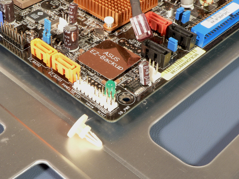
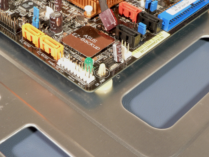
Yet another issue with the motherboard tray was a missing hole for a standoff at the bottom right corner of the motherboard. This is a standard location for full-sized ATX boards, so its presence was surely missed. Fortunately, I had an old plastic standoff in my toolbox that I was able to put it its place. Again, Thermaltake has informed me that this is being corrected.
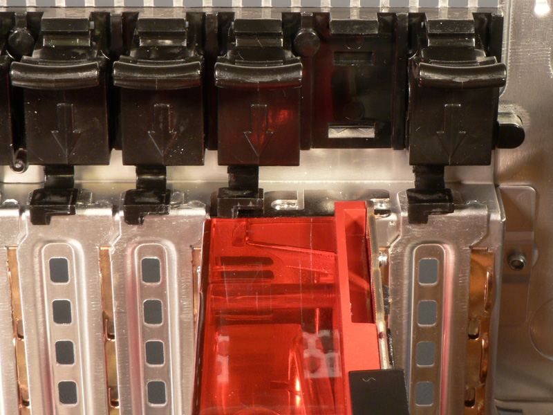
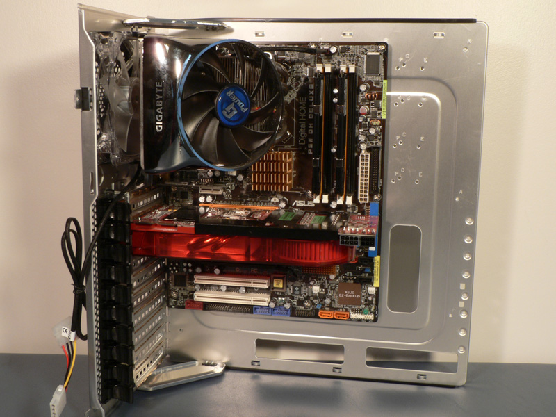
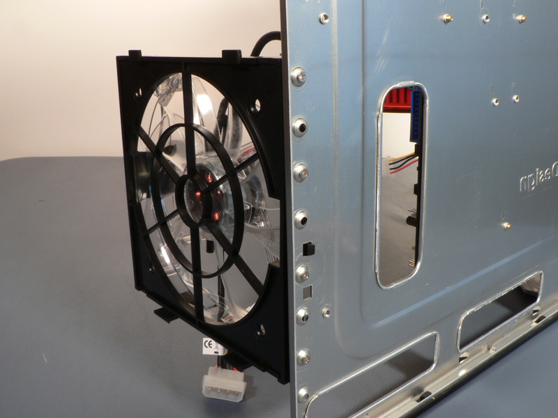
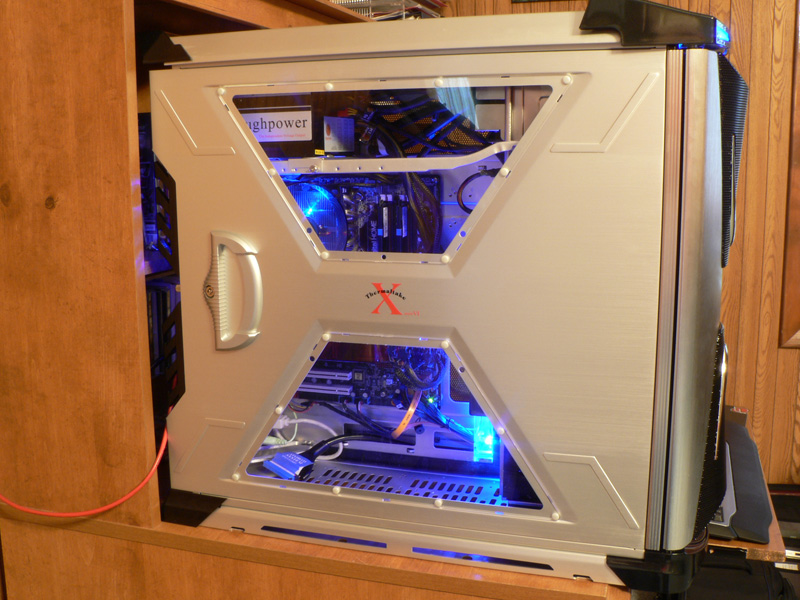
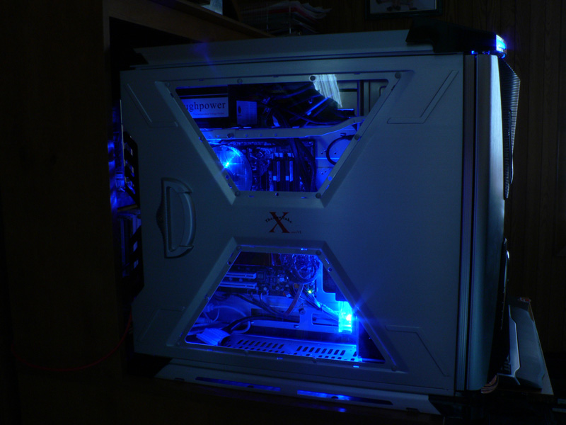
Next to install was the video card. The Sapphire HD 2900XT needed two of the black clips to be removed, but when they were put back into place the red plastic cover for the cooler kept the tab on the bottom of the clip from going into the proper place. I did not consider this much of a problem, though, as I was more comfortable with using screws to hold the video card in place. With the components installed it is evident how big the tray is; with the full-sized motherboard and a long video card installed they both seem undersized on the huge tray. Along the front edge of the motherboard tray there are some holes that allow the extra 140mm fan to be mounted there, pushing cool air from the front of the case across the video card(s). Please note that I chose to swap out the blue LED fan from the front of the case with the black and red fan in the accessory box. Adding the LED fan here instead would add more light to the case inside.
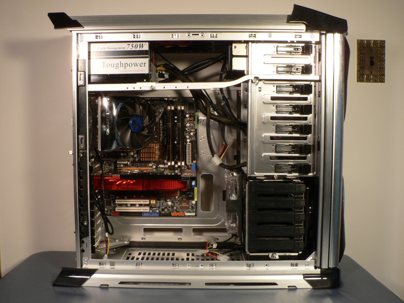
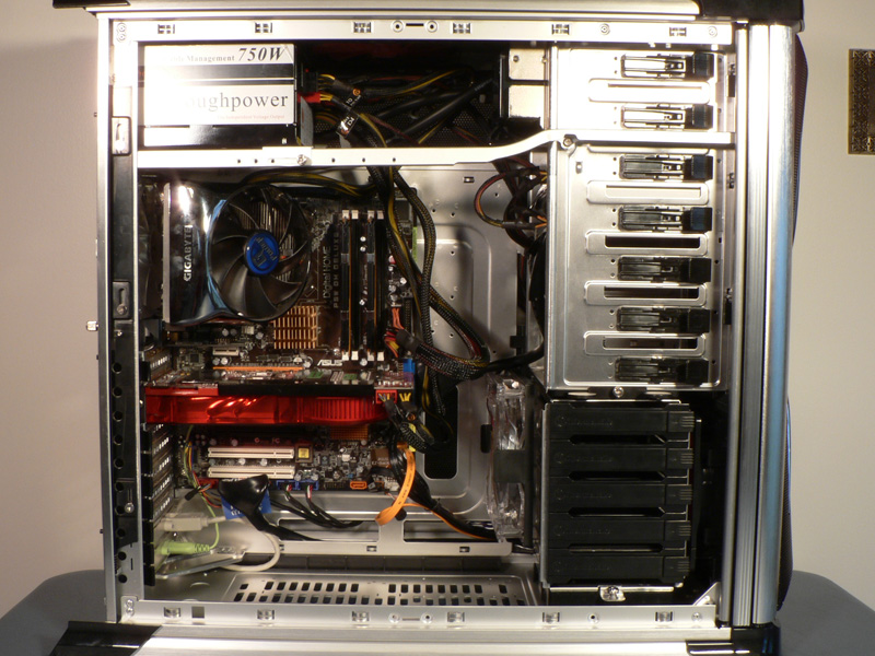
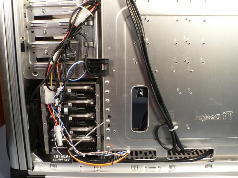
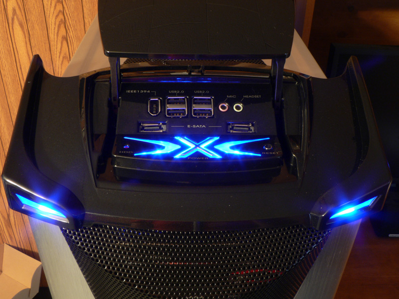
With the tray installed it was time to start running all the cables, and this is where the extra features start to come in handy. The holes in the motherboard tray were perfect for routing cables, and they were in the right locations. The HDD cage being rotated allowed all the power wires and data cables to virtually disappear, and all the cable ties came in handy to tidy everything up. The only problem I had here was that the Audio cable for the front I/O panel was not long enough to go all the way to the header located at the back of the motherboard. It would have been nice to have another six inches or so for most of the front I/O panel cables, just to make sure they were easily routable.
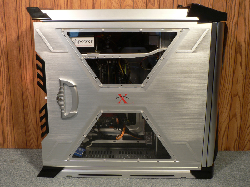
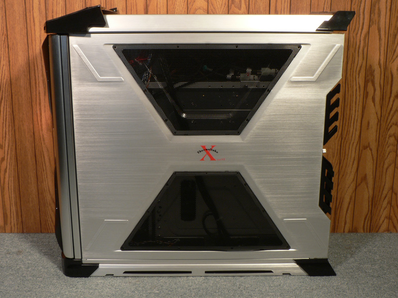
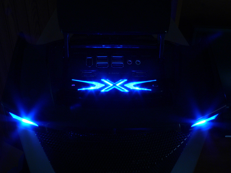
Finished Look
Mar 10th, 2025 22:11 EDT
change timezone
Latest GPU Drivers
New Forum Posts
- Nvidia's GPU market share hits 90% in Q4 2024 (gets closer to full monopoly) (798)
- Biostar RX 6700 XT OC BIOS (8)
- Mind If I Play Through? (11)
- ThrottleStop, mistake (4)
- ThrottleStop, auto-launching (1)
- Post your Old CDs, from back in the day thread. (3)
- AMD RX 9070 XT & RX 9070 non-XT thread (OC, undervolt, benchmarks, ...) (8)
- Wherein lies the difference (3)
- What's your latest tech purchase? (23279)
- CPU downclocks under any loads but it doesn't hit any limits (1)
Popular Reviews
- Sapphire Radeon RX 9070 XT Nitro+ Review - Beating NVIDIA
- XFX Radeon RX 9070 XT Mercury OC Magnetic Air Review
- ASUS Radeon RX 9070 TUF OC Review
- MSI MAG B850 Tomahawk Max Wi-Fi Review
- NVIDIA GeForce RTX 5070 Founders Edition Review
- Corsair Vengeance RGB CUDIMM DDR5-8800 48 GB CL42 Review
- AMD Ryzen 7 9800X3D Review - The Best Gaming Processor
- ASUS GeForce RTX 5070 Ti TUF OC Review
- MSI GeForce RTX 5070 Ti Gaming Trio OC+ Review
- MSI GeForce RTX 5070 Ti Ventus 3X OC Review
Controversial News Posts
- NVIDIA GeForce RTX 50 Cards Spotted with Missing ROPs, NVIDIA Confirms the Issue, Multiple Vendors Affected (513)
- AMD Plans Aggressive Price Competition with Radeon RX 9000 Series (277)
- AMD Radeon RX 9070 and 9070 XT Listed On Amazon - One Buyer Snags a Unit (261)
- AMD RDNA 4 and Radeon RX 9070 Series Unveiled: $549 & $599 (260)
- AMD Mentions Sub-$700 Pricing for Radeon RX 9070 GPU Series, Looks Like NV Minus $50 Again (248)
- NVIDIA Investigates GeForce RTX 50 Series "Blackwell" Black Screen and BSOD Issues (244)
- AMD Radeon RX 9070 and 9070 XT Official Performance Metrics Leaked, +42% 4K Performance Over Radeon RX 7900 GRE (195)
- AMD Radeon RX 9070-series Pricing Leaks Courtesy of MicroCenter (158)