 10
10
Xilence Interceptor Pro Review
Assembly & Finished Looks »A Closer Look - Inside - HPTX Area
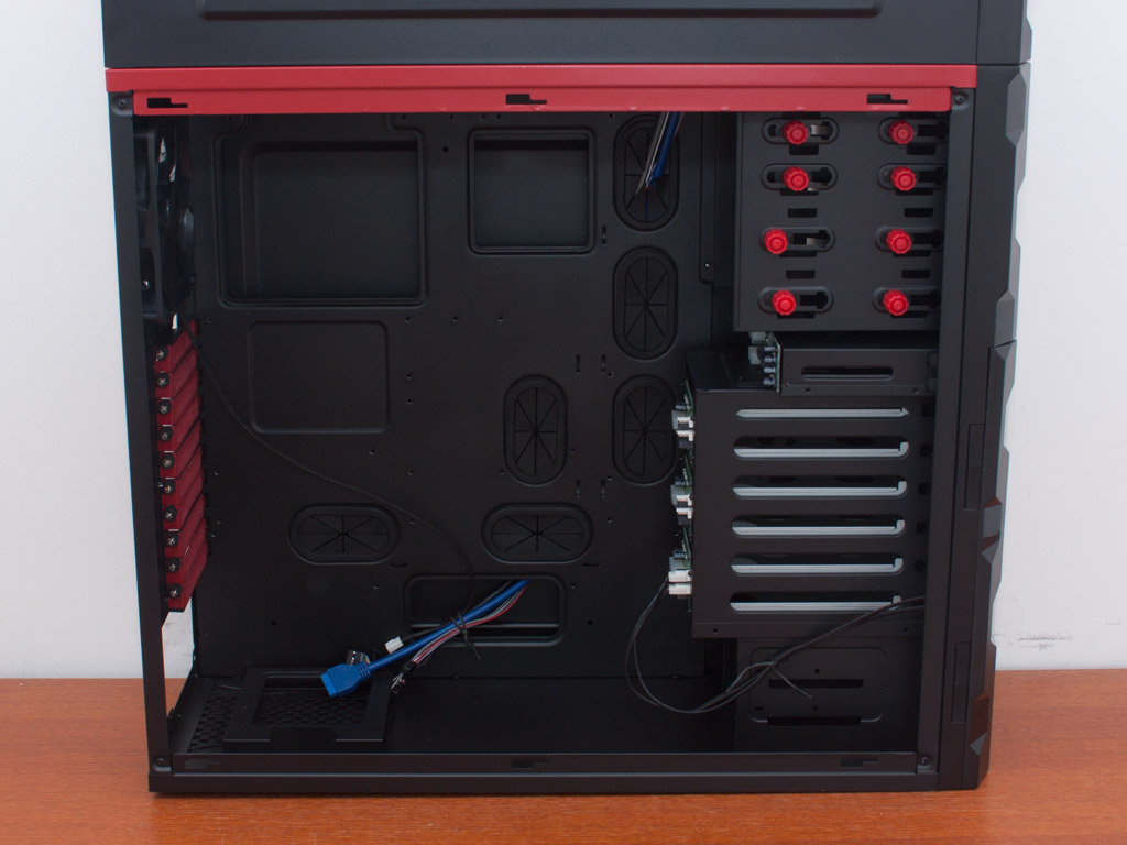
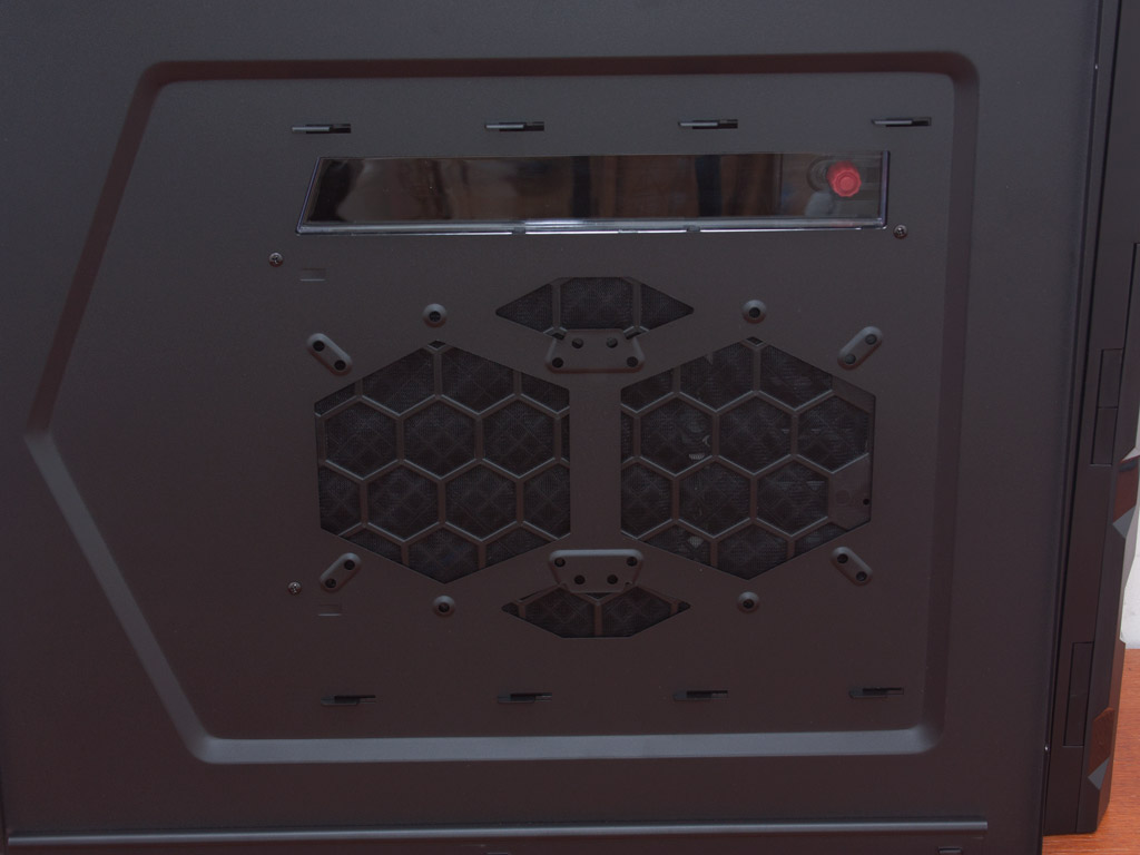
To gain access to the HPTX area of the case, one has to simply remove the pair of thumb screws holding each panel in place. The interior of the chassis is all black, besides the red expansion slot covers and the divider between HPTX and ITX cases. You may install two 120 or 140 mm fans in the main side panel or go for a single 200 mm one.
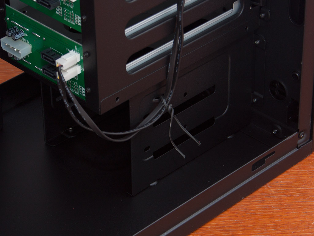
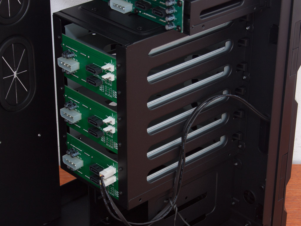
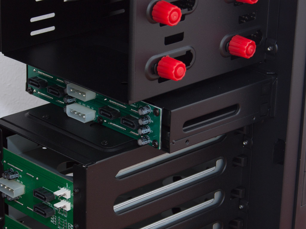
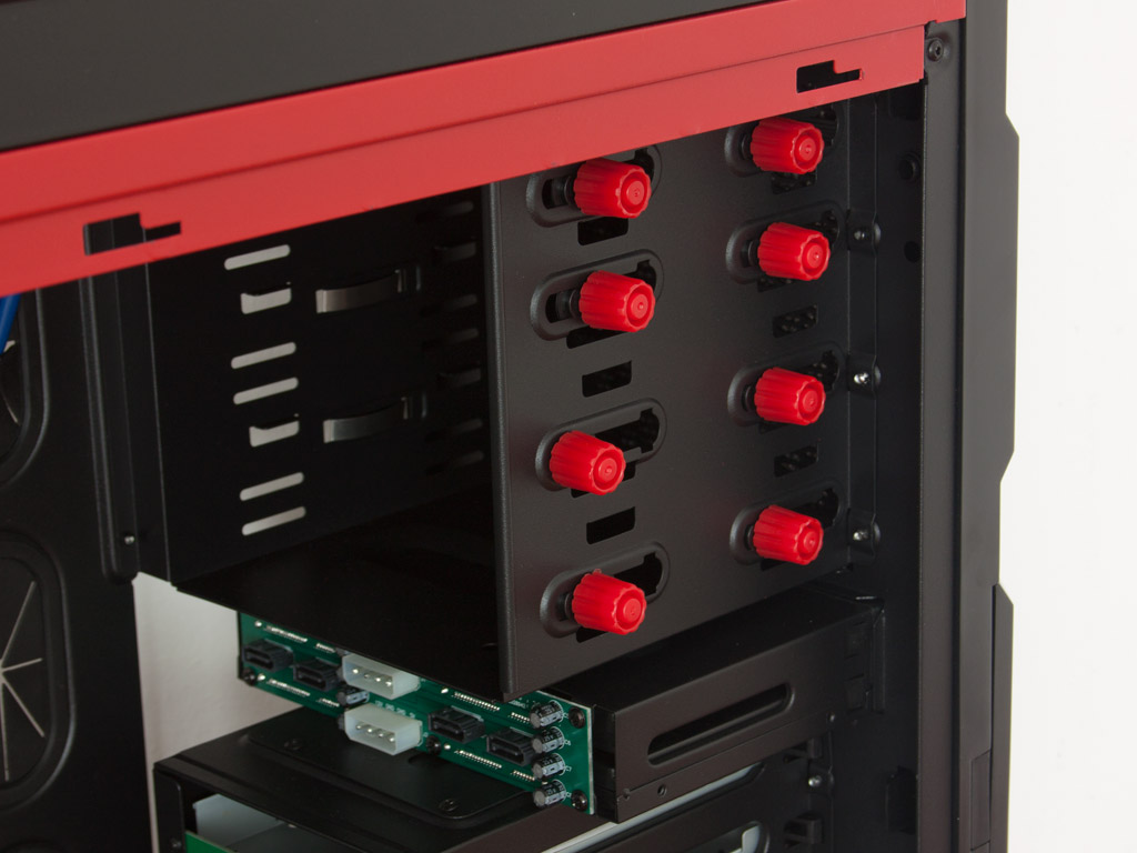
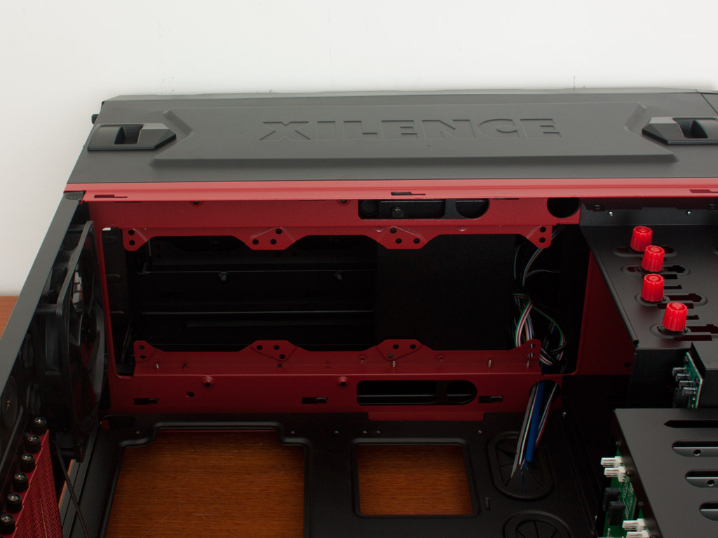
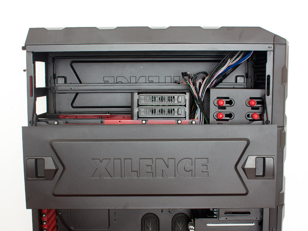
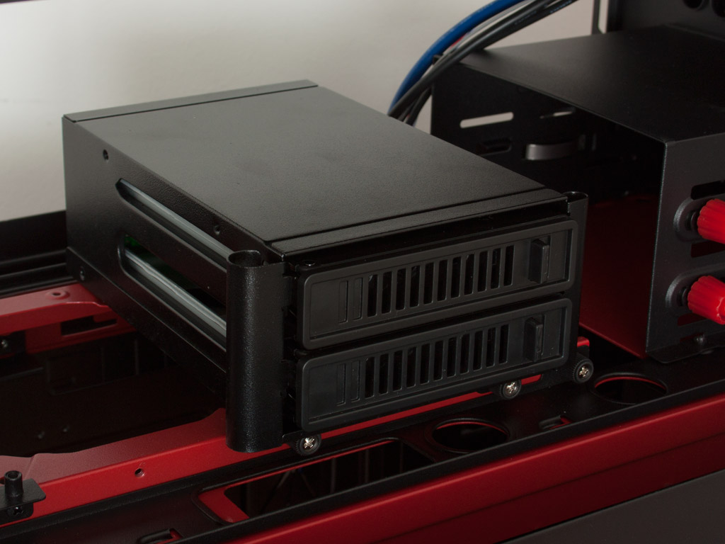
There are two traditional 3.5 inch drive bays, which are not accessible from the outside. You will have to use traditional screws to pin these down. Above that are the six 3.5 inch hot-swap bays with actual high-quality PCBs attached to these bays. Such an implementation has the obvious benefit that it is studier, but also enables the use of single Molex connectors to power two drives. This reduces overall cable clutter considerably. On top of that, Xilence has also included two fan headers on each of these PCBs, allowing you to connect six cooling units to them. The four 2.5 inch bays are quite similar as they are using a single Molex for two drives as well. The only downside here is the fact that it is not really clear which SATA connector goes for which drive. In the very top area of the HPTX compartment, the 5.25 inch bays utilize a tool-less design that is not only simple, but also extremely effective. Behind each of the red knobs is an embedded screw, which means in essence, that you are actually screwing each drive down properly but without the need for any tools.
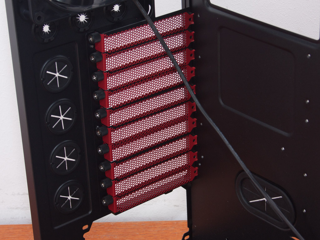

Turning our focus to the rear of the chassis, the bottom PSU bay is nothing out of the ordinary. There is a removable dust filter in this area to keep grime out of the power supply. Above that are the afore mentioned ten motherboard expansion slots with each cover held in place by thumb screws as well. In the very top, there is the 140 mm exhaust fan with piano finish and black blades. I should mention at this point, that all fan cables are sleeved nicely, to keep with the all black looks of the case.
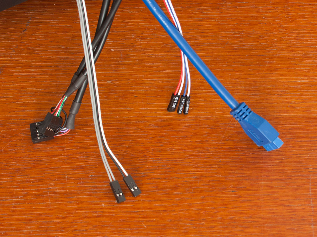
The ceiling of the HPTX area allows for up to three 120 mm fans or a 360 mm radiator to be installed within the chassis. Doing so is certainly pretty cool, but temperatures in the ITX compartment would suffer if you were to do so. Unfortunately, all the cables within the Interceptor Pro are of the default colors, which disturbs the look a bit. On top of that, there is no clear labels to which part of the chassis these cables belong, so you have to make sure to install the right ones to the right board.
A Closer Look - Inside - ITX Area
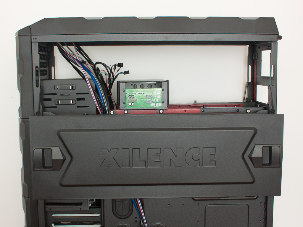
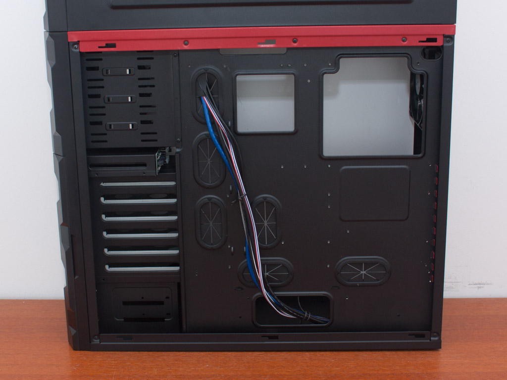
To gain access to the ITX part of the Interceptor Pro, simply push the spring loaded locks in the right direction. The covers will then lower down, thanks to a fairly elaborate mechanism. The only gripe I have with these panels is the somewhat flimsy construction of the locks. While they work quite alright, they do feel a bit fragile. The entire area of the top is used for the ITX system, spreading things around across the entire length of the case.
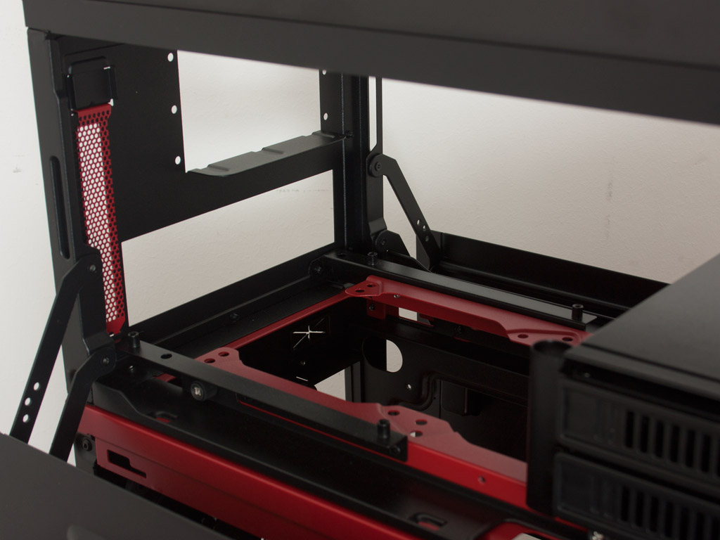
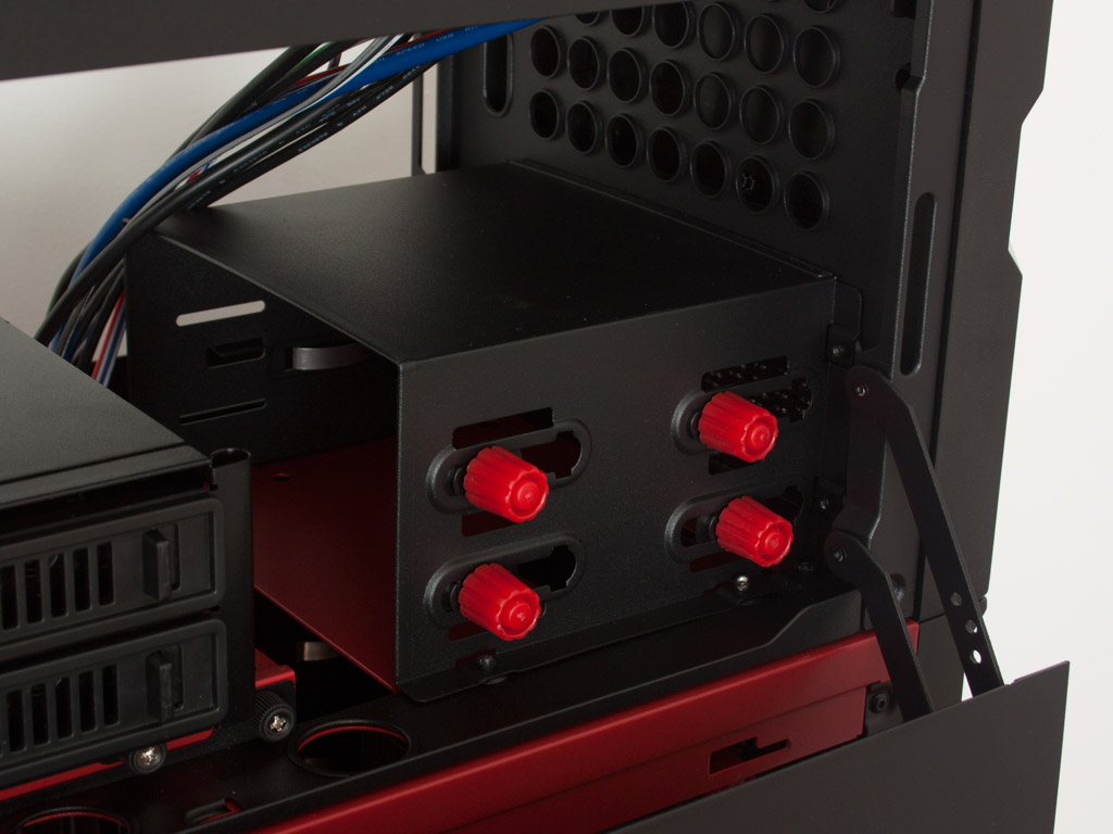
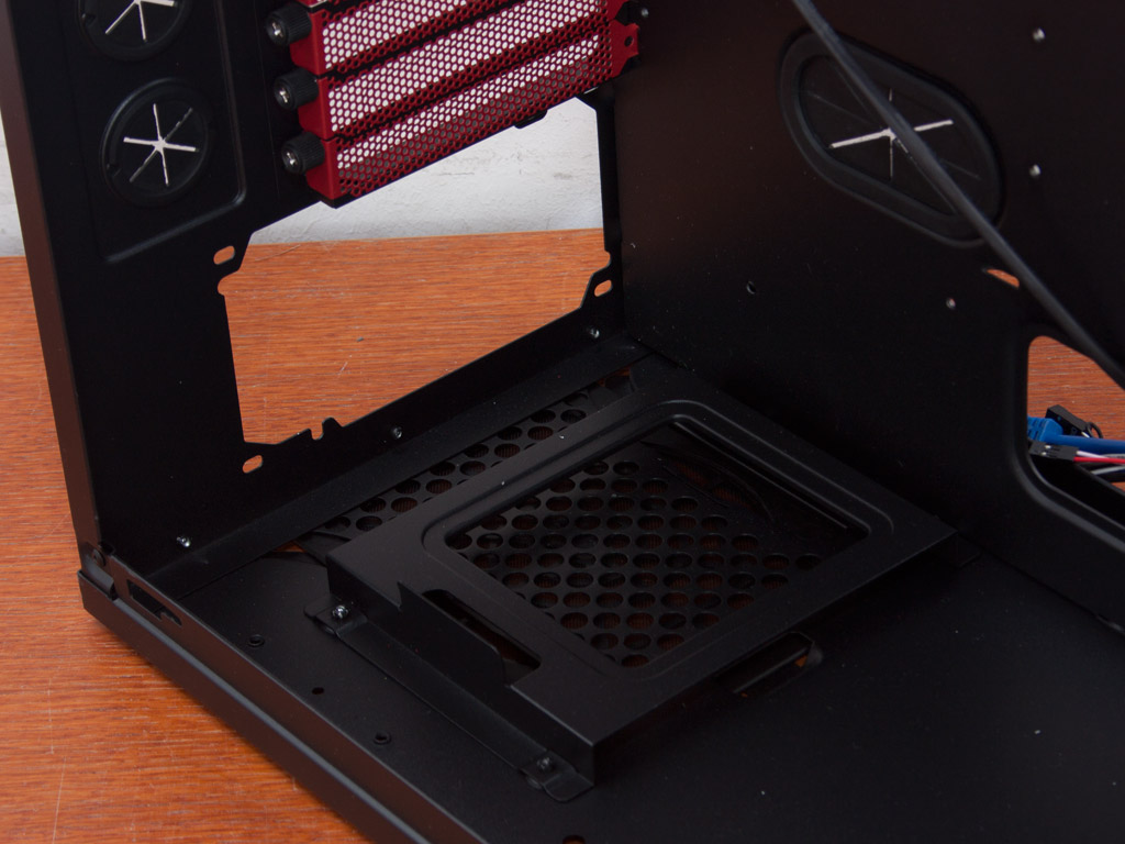
In the very rear, there is the motherboard area. The Mini-ITX board is placed in the case horizontally, with the SFX PSU above it. This means, that you will not be able to use big CPU coolers here. In the middle are two additional hot-swap capable HDD bays using the same system as the ones in the HPTX area. This means that you could swap drives on the fly from one system to another if need be - pretty cool. In the front you will find the two external 5.25 inch bays with the same tool-less mounting system as the ones below.
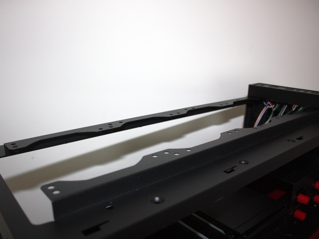
Due to the size of the chassis, I was unable to take a proper picture of the 4x120 mm / 3x 140 mm fan placements in the very top of the Interceptor Pro. You could also install a massive 480 mm or 420 mm radiator here if you really wanted to - pretty crazy!
Jul 3rd, 2025 21:39 CDT
change timezone
Latest GPU Drivers
New Forum Posts
- What Windows is overall the best to you and why? (267)
- How do you view TPU & the internet in general? (With poll) (58)
- HP Zbook 15 G2 GPU Upgrade (12)
- Will you buy a RTX 5090? (610)
- What phone you use as your daily driver? And, a discussion of them. (1756)
- GPU-Z Display Bug via DP 2.1? (3)
- What would you buy? (51)
- A Final Fantasy IX Reminiscence - My love letter and homage to one of the best stories ever told (90)
- GravityMark v1.89 GPU Benchmark (309)
- RTX 5070 discussion (5)
Popular Reviews
- ASUS ROG Crosshair X870E Extreme Review
- Crucial T710 2 TB Review - Record-Breaking Gen 5
- Fractal Design Scape Review - Debut Done Right
- PowerColor ALPHYN AM10 Review
- Sapphire Radeon RX 9060 XT Pulse OC 16 GB Review - An Excellent Choice
- Upcoming Hardware Launches 2025 (Updated May 2025)
- AMD Ryzen 7 9800X3D Review - The Best Gaming Processor
- Sapphire Radeon RX 9070 XT Nitro+ Review - Beating NVIDIA
- SCHENKER KEY 18 Pro (E25) Review - Top-Tier Contender
- AVerMedia CamStream 4K Review
TPU on YouTube
Controversial News Posts
- Intel's Core Ultra 7 265K and 265KF CPUs Dip Below $250 (288)
- NVIDIA Grabs Market Share, AMD Loses Ground, and Intel Disappears in Latest dGPU Update (212)
- Some Intel Nova Lake CPUs Rumored to Challenge AMD's 3D V-Cache in Desktop Gaming (140)
- NVIDIA GeForce RTX 5080 SUPER Could Feature 24 GB Memory, Increased Power Limits (115)
- Microsoft Partners with AMD for Next-gen Xbox Hardware (105)
- NVIDIA Launches GeForce RTX 5050 for Desktops and Laptops, Starts at $249 (105)
- Intel "Nova Lake‑S" Series: Seven SKUs, Up to 52 Cores and 150 W TDP (100)
- NVIDIA DLSS Transformer Cuts VRAM Usage by 20% (97)