 11
11
XPG Core Reactor 750 W Review
Voltage Regulation Stability & Ripple »Component Analysis
Before reading this page, we strongly suggest a look at this article, which will help you understand the internals of a PSU better.| XPG Core Reactor 750 W Parts Description | |
|---|---|
| General Data | |
| Manufacturer (OEM) | CWT |
| PCB Type | Double-sided |
| Primary Side | |
| Transient Filter | 4x Y caps, 2x X caps, 2x CM chokes, 1x MOV |
| Bridge Rectifier(s) | 2x GBU15L06 (600 V, 15 A @ 115 °C) |
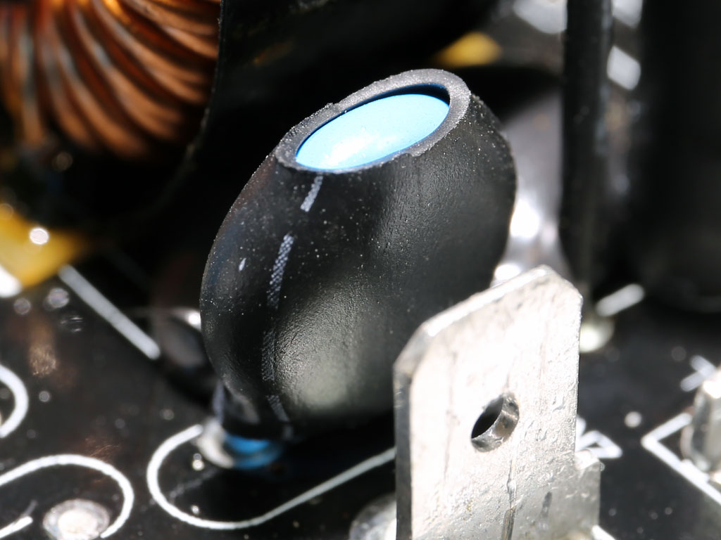
| Inrush Current Protection | NTC Thermistor & Relay |
| APFC MOSFETs | 2x Vishay SiHF30N60E (650 V, 18 A @ 100 °C, 0.125 ohm) & 1x SPN5003 FET (for reduced no-load consumption) |
| APFC Boost Diode | 1x CREE C3D10060A (600 V, 10 A @ 150 °C) |
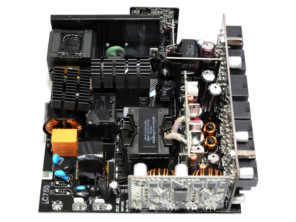
| Hold-up Cap(s) | 1x Nippon Chemi-Con (420 V, 680 uF, 2,000 h @ 105 °C KMZ) |
| Main Switchers | 2x Vishay SiHF30N60E (650 V, 18 A @ 100 °C, 0.125 ohm) |
| APFC Controller | Champion CM6500UNX |
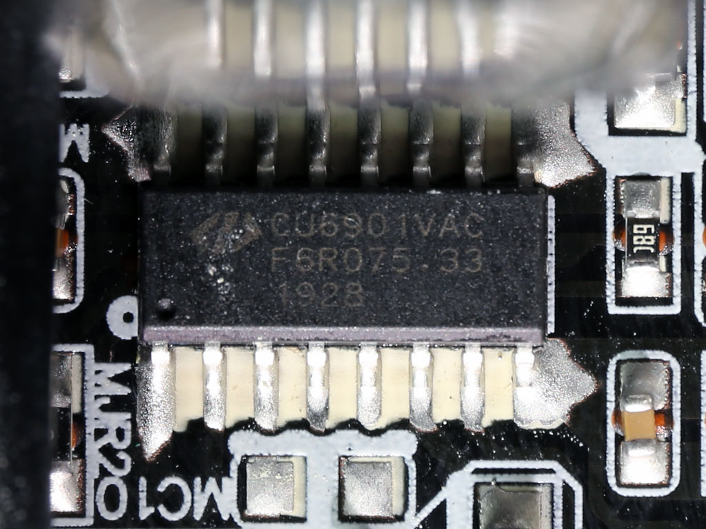
| Switching Controller | Champion CU6901V |
| Topology | Primary side: Half-bridge & LLC converter Secondary side: Synchronous Rectification & DC-DC converters |
| Secondary Side | |
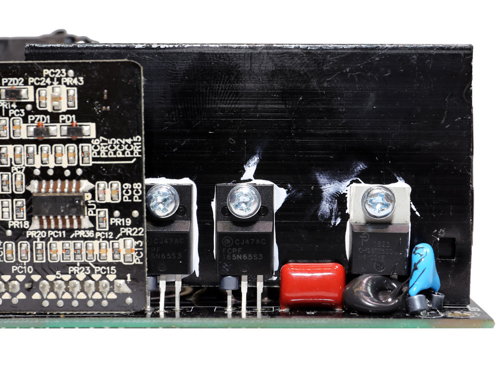
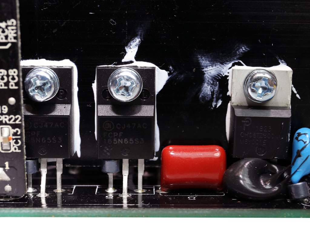
| +12 V MOSFETs | 8x On Semiconductor NTMFS5C430N (40 V, 131 A @ 100 °C, 1.7 mOhm) |
| +5 V & +3.3 V | DC-DC Converters:
|
| Filtering Capacitors | Electrolytic: |
| Supervisor IC | IN1S313I-SAG |
| Fan Model | Hang Hua HA1225H12F-Z (120 mm, 12 V, 0.58 A, fluid dynamic bearing fan) |
| 5VSB Circuit | |
| Rectifier(s) | Silan Microelectronics SVF4N65RDTR FET (650 V, 2.5 A @ 100 °C, 2.7 ohm), |
| Standby PWM Controller | On-Bright OB5282CP |
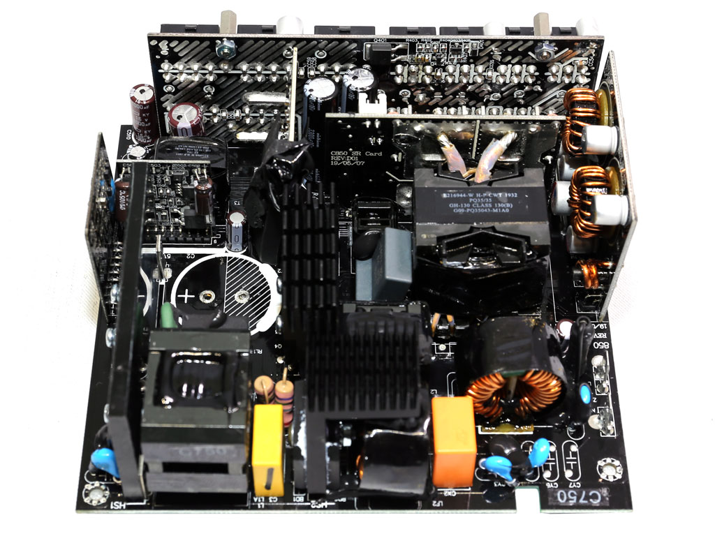
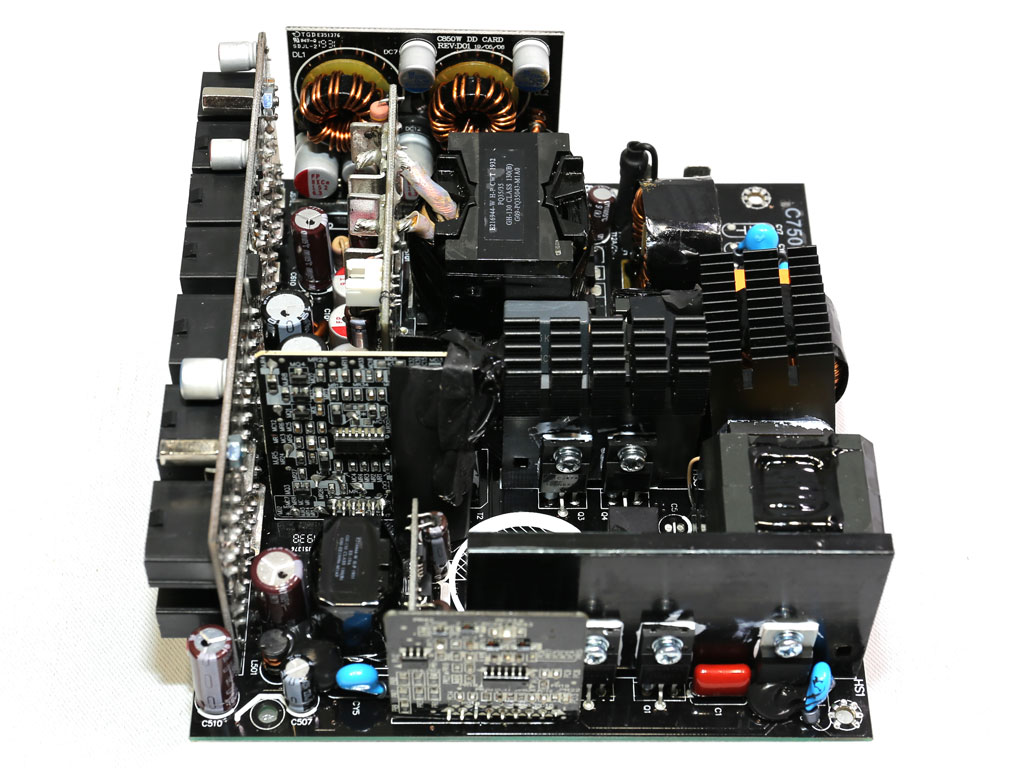
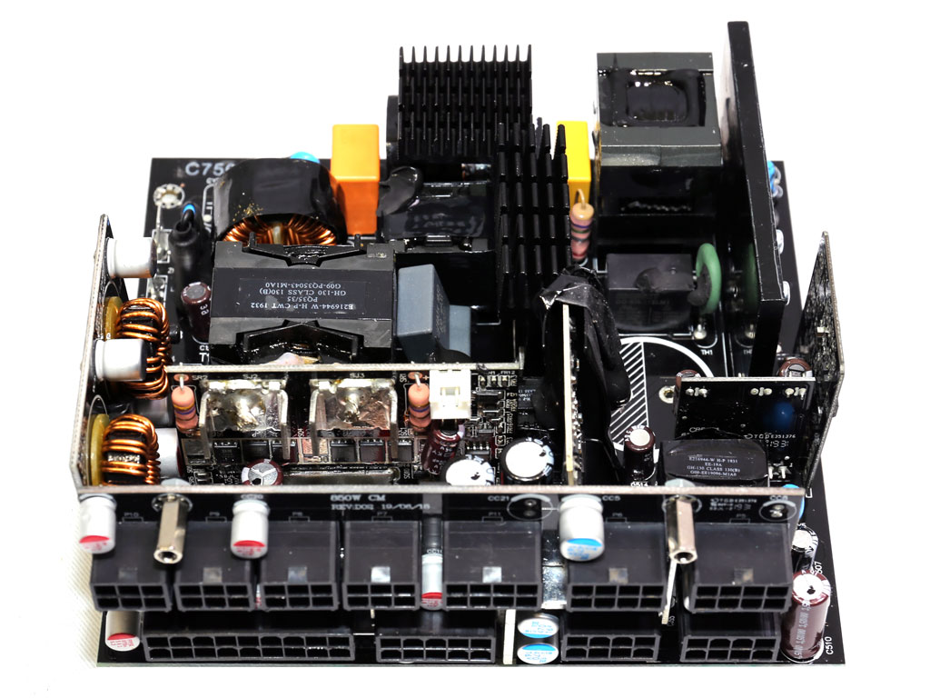
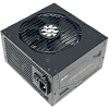
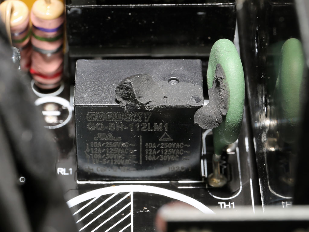
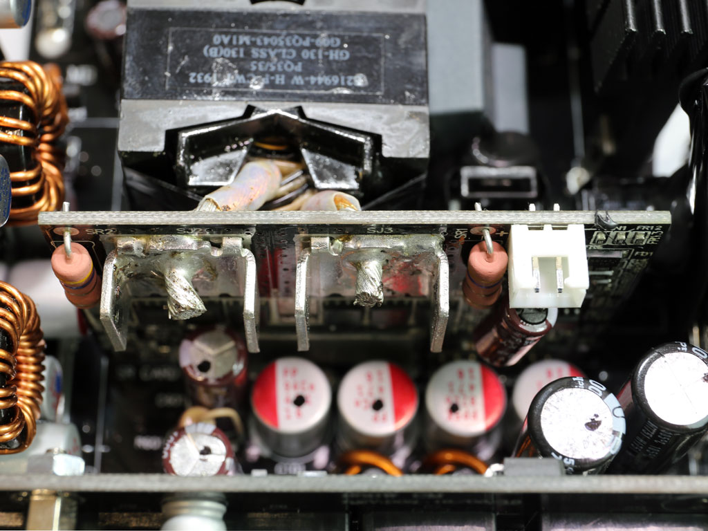
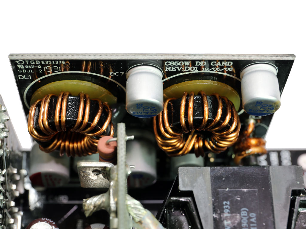
This is a new CWT platform with a very small PCB for its maximum power output. The design is clean as most power transfers are done through PCB traces instead of wires. However, such an overpopulated PCB doesn't allow for much space between components, so airflow won't be optimal. There are no proper heatsinks on the secondary side, which is typical for a CWT design, and the main transformer is connected to the +12 V board with a pair of short and thick wires. The +12 V board is right next to the main transformer to minimize energy losses and increase efficiency.
The transient filter has all the required components to suppress power surges and EMI emissions.
There is an NTC thermistor and bypass relay combo for restricting large inrush currents.

Each of the two bridge rectifiers can handle up to 15 A. They have been installed in parallel.
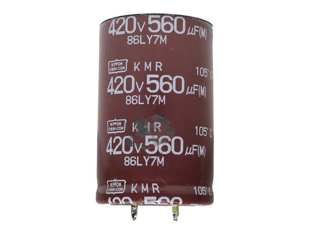

The APFC converter uses quality components, including a Chemi-Con cap rated at 420 V instead of the 400 V many manufacturers use to decrease cost.


The primary switching FETs are configured in a half-bridge topology. A resonant converter is also utilized to reduce energy losses.
The FETs that regulate the +12 V rail are installed on a vertical board right next to the main transformer. CWT uses a few small heatsinks to cool down these FETs.

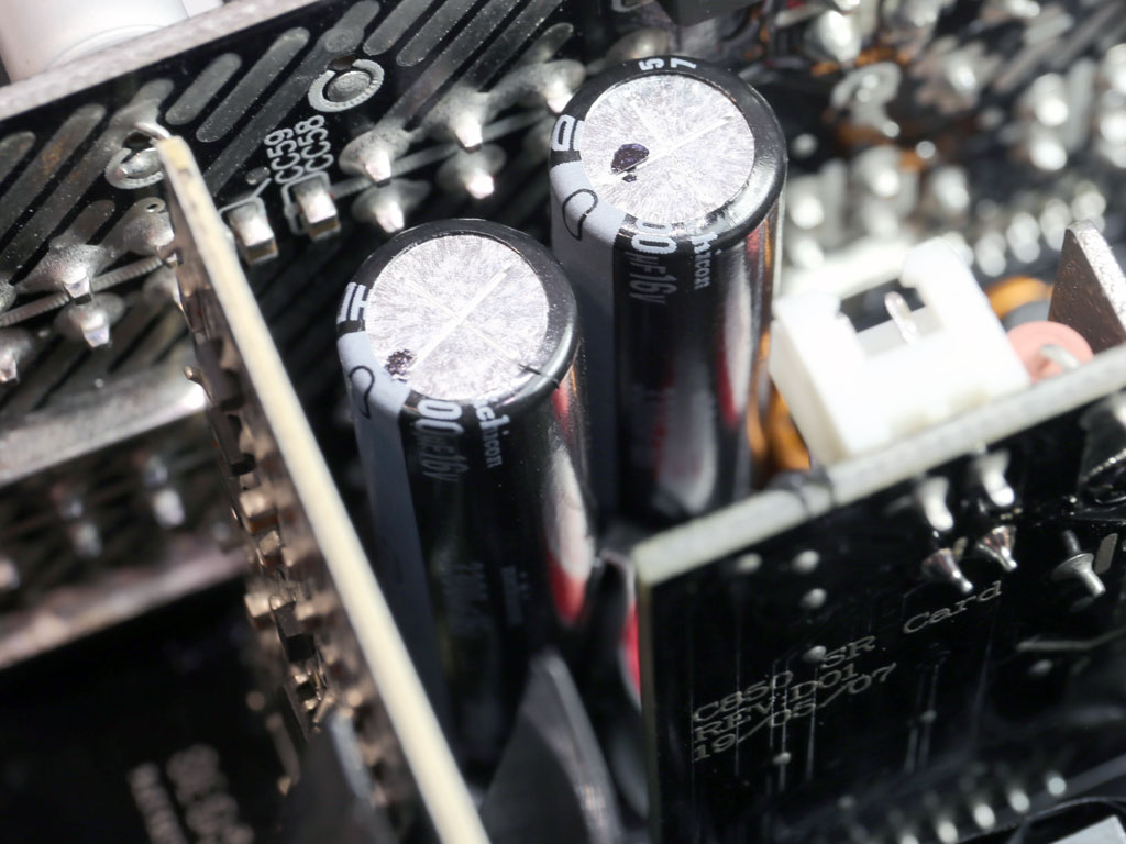
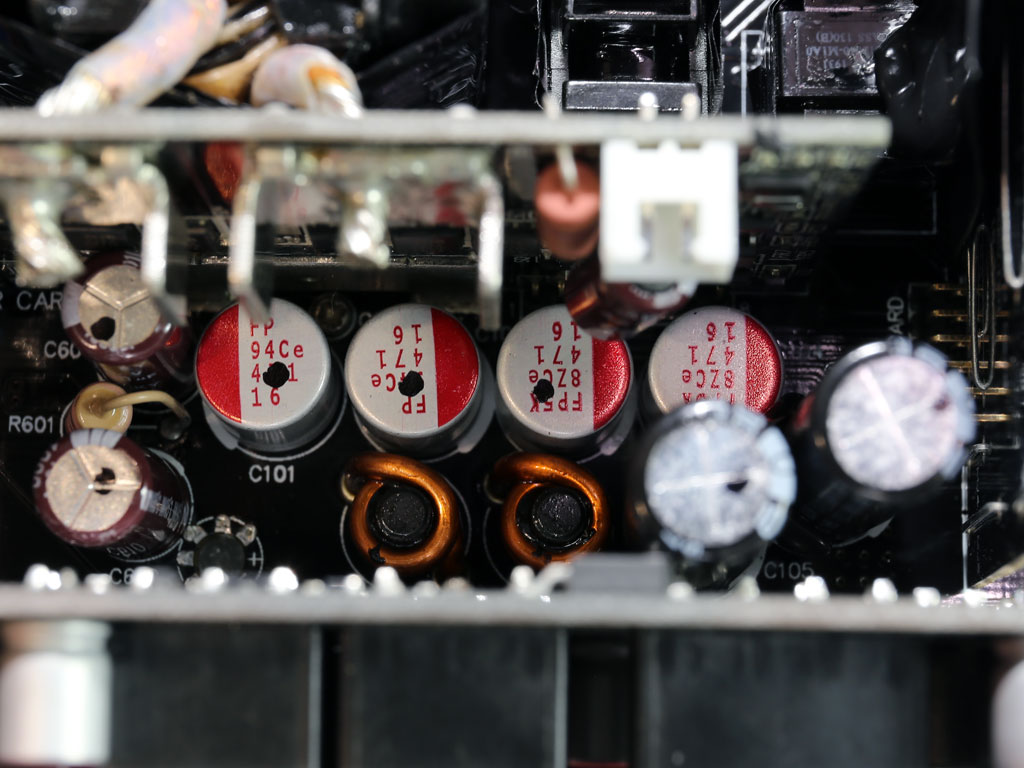
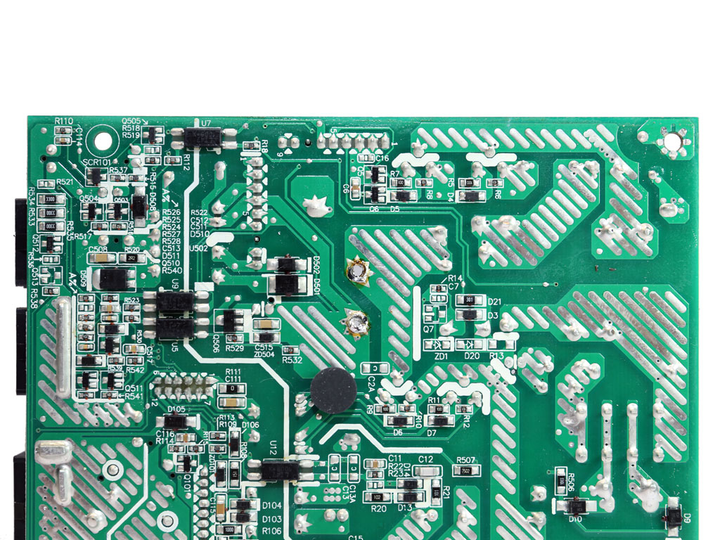
The majority of electrolytic caps are of very high quality. Many polymer caps are also used for ripple-filtering purposes.
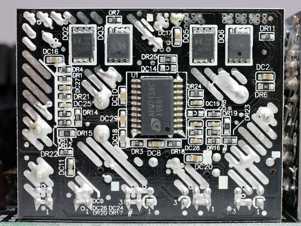
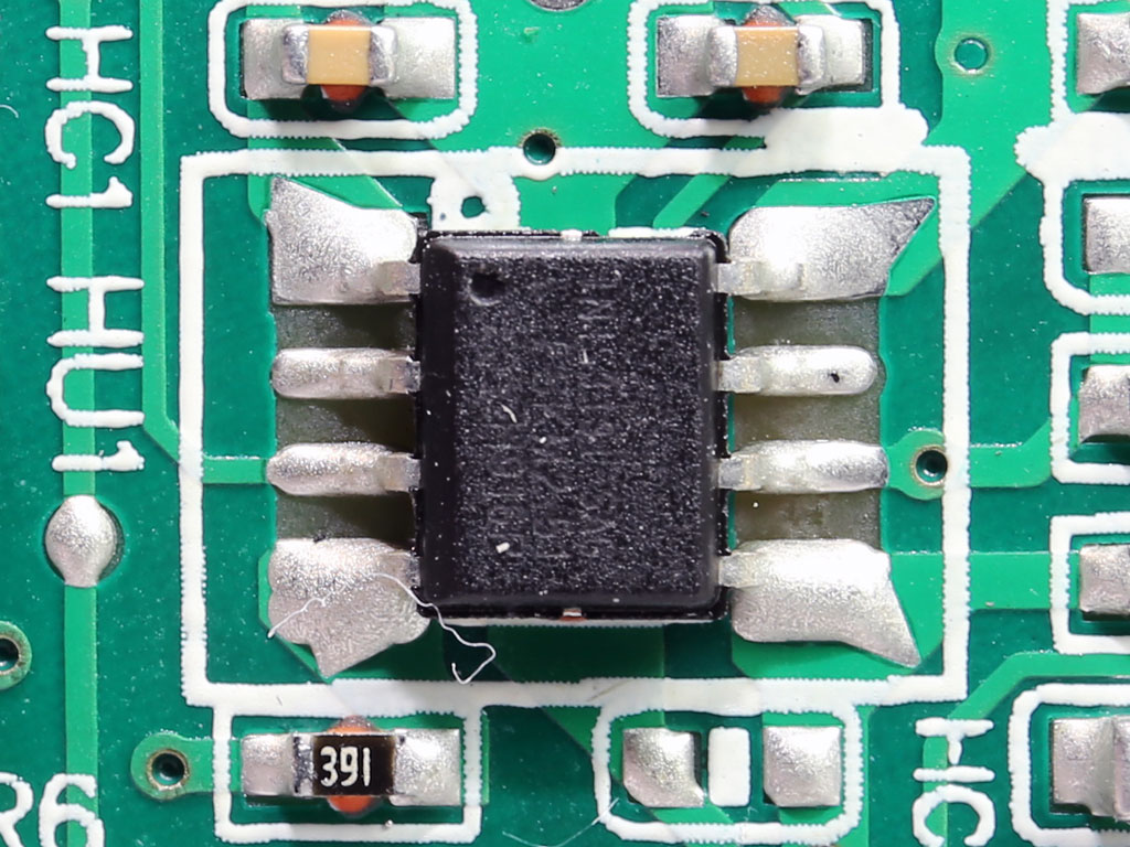
Two voltage regulation modules generate the minor rails.

The 5VSB circuit uses a FET on its primary side and an SBR on its secondary side.
The supervisor IC is an IN1S313I-SAG.


Lots of polymer caps are installed on the modular board as an extra ripple filtering stage.
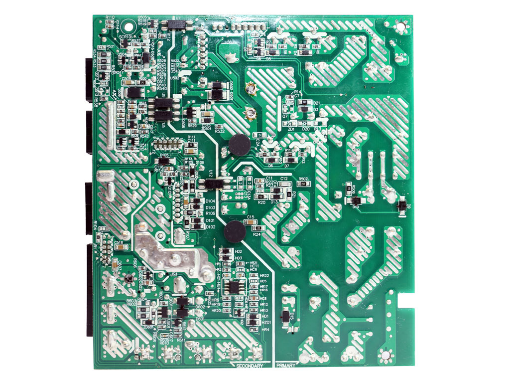

As per usual for CWT, soldering quality is good.
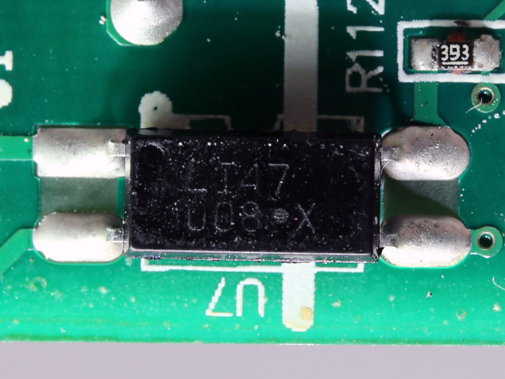

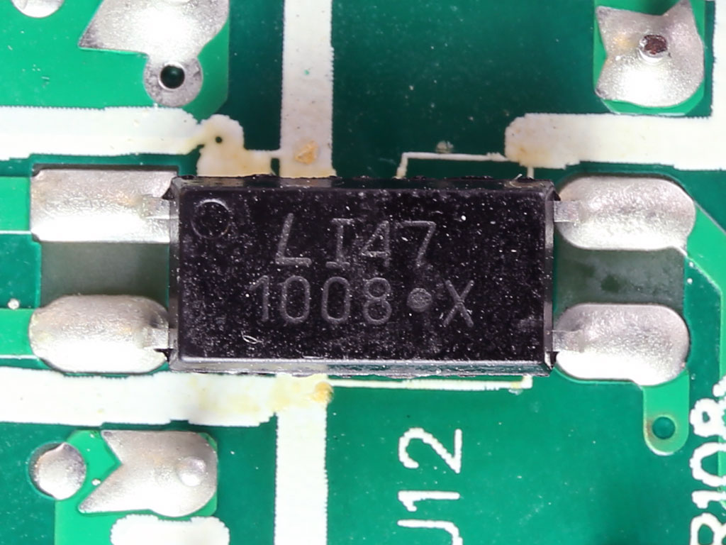

As is usually is the case, optocouplers are used to pass signals between the primary and secondary sides.
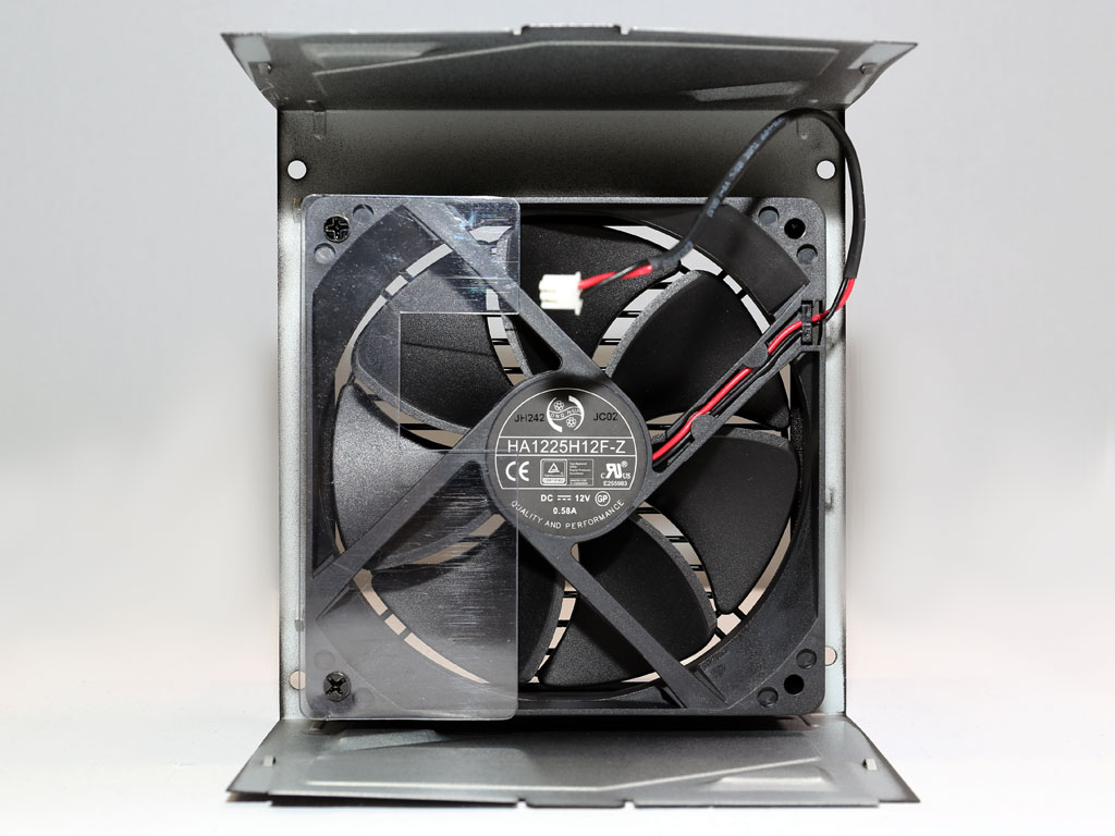

The cooling fan is provided by Hong Hua, a company that has managed to conquer the PSU manufacturing market with its fans. It uses a fluid dynamic bearing and measures 120 mm across.
Jul 5th, 2025 13:33 CDT
change timezone
Latest GPU Drivers
New Forum Posts
- Help Watercooling my PC (1)
- TPU's Nostalgic Hardware Club (20484)
- FINAL FANTASY XIV: Dawntrail Official Benchmark (195)
- How do you view TPU & the internet in general? (With poll) (71)
- GravityMark v1.89 GPU Benchmark (310)
- Optane performance on AMD vs Intel (57)
- EVGA XC GTX 1660 Ti 8GB ROM (8)
- Are there others on TPU with a dual system (two pc´s in one case)? (9)
- TPU's Rosetta Milestones and Daily Pie Thread (2374)
- Have you got pie today? (16775)
Popular Reviews
- NVIDIA GeForce RTX 5050 8 GB Review
- Fractal Design Scape Review - Debut Done Right
- Crucial T710 2 TB Review - Record-Breaking Gen 5
- ASUS ROG Crosshair X870E Extreme Review
- PowerColor ALPHYN AM10 Review
- Sapphire Radeon RX 9060 XT Pulse OC 16 GB Review - An Excellent Choice
- Upcoming Hardware Launches 2025 (Updated May 2025)
- AMD Ryzen 7 9800X3D Review - The Best Gaming Processor
- Sapphire Radeon RX 9070 XT Nitro+ Review - Beating NVIDIA
- NVIDIA GeForce RTX 5060 8 GB Review
TPU on YouTube
Controversial News Posts
- Intel's Core Ultra 7 265K and 265KF CPUs Dip Below $250 (288)
- NVIDIA Grabs Market Share, AMD Loses Ground, and Intel Disappears in Latest dGPU Update (212)
- Some Intel Nova Lake CPUs Rumored to Challenge AMD's 3D V-Cache in Desktop Gaming (140)
- NVIDIA GeForce RTX 5080 SUPER Could Feature 24 GB Memory, Increased Power Limits (115)
- NVIDIA Launches GeForce RTX 5050 for Desktops and Laptops, Starts at $249 (105)
- Microsoft Partners with AMD for Next-gen Xbox Hardware (105)
- AMD Radeon RX 9070 XT Gains 9% Performance at 1440p with Latest Driver, Beats RTX 5070 Ti (102)
- Intel "Nova Lake‑S" Series: Seven SKUs, Up to 52 Cores and 150 W TDP (100)