 9
9
Aerocool Project 7 PSU 650 W Review
Ripple Measurements »Advanced Transient Response Tests
In these tests, we monitor the response of the PSU in two different scenarios. First, a transient load (10 A at +12V, 5 A at 5V, 5 A at 3.3V, and 0.5 A at 5VSB) is applied to the PSU for 200 ms while the latter is working at 20% load. In the second scenario, the PSU, while working at 50% load, is hit by the same transient load. In both tests, we measure the voltage drops the transient load causes using our oscilloscope. The voltages should remain within the regulation limits defined by the ATX specification. We must stress here that these tests are crucial since they simulate transient loads a PSU is very likely to handle (e.g., booting a RAID array, an instant 100% load of CPU/VGAs, etc.). We call these tests Advanced Transient Response tests, and they are designed to be very tough to master, especially for a PSU with a capacity below 500 W.| Advanced Transient Response 20% - 5 Hz | ||||
|---|---|---|---|---|
| Voltage | Before | After | Change | Pass/Fail |
| 12 V | 12.170V | 12.027V | 1.18% | Pass |
| 5 V | 5.064V | 4.981V | 1.64% | Pass |
| 3.3 V | 3.357V | 3.196V | 4.80% | Pass |
| 5VSB | 5.035V | 4.981V | 1.07% | Pass |
| Advanced Transient Response 50% - 5 Hz | ||||
|---|---|---|---|---|
| Voltage | Before | After | Change | Pass/Fail |
| 12 V | 12.141V | 12.009V | 1.09% | Pass |
| 5 V | 5.059V | 4.975V | 1.66% | Pass |
| 3.3 V | 3.346V | 3.195V | 4.51% | Pass |
| 5VSB | 5.016V | 4.975V | 0.82% | Pass |
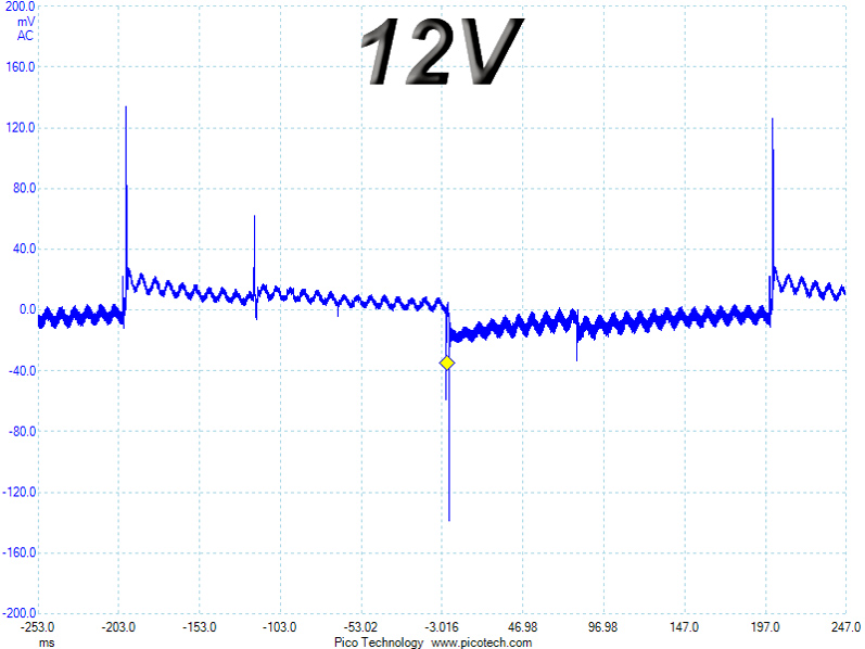
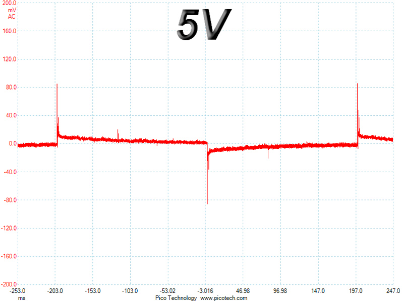
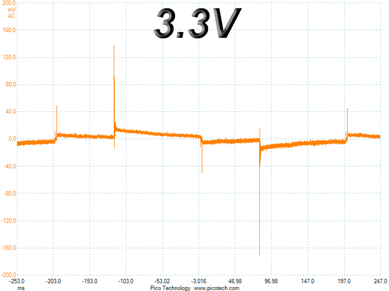
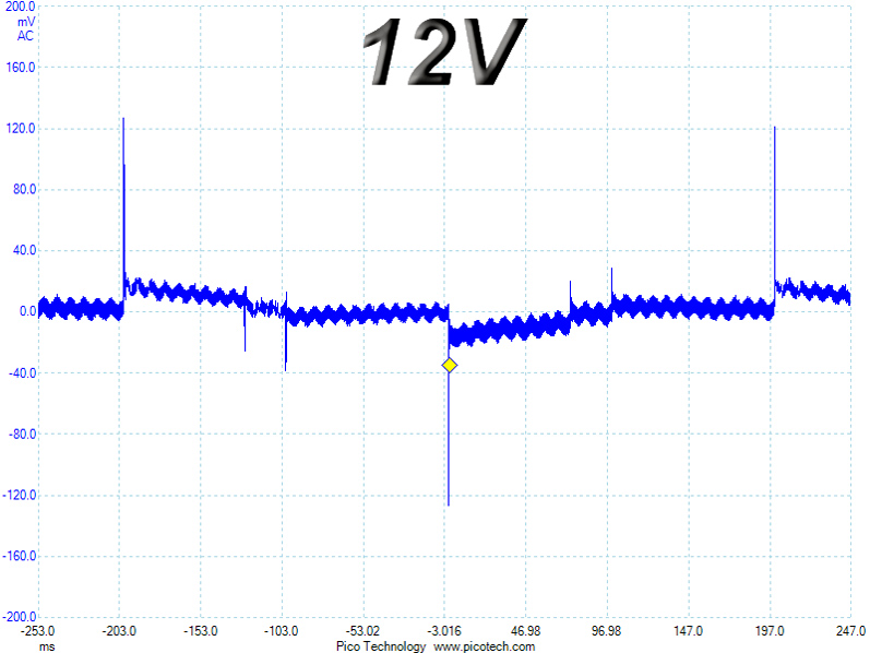
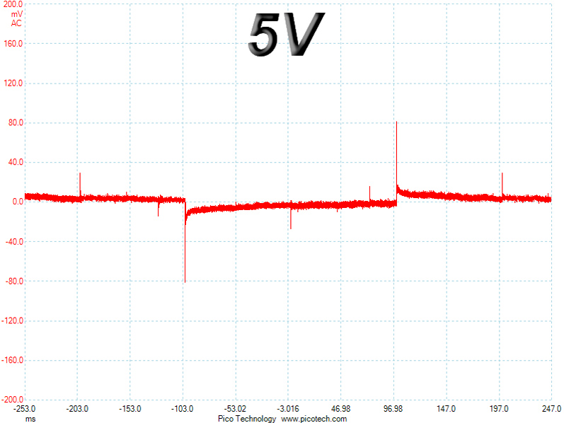
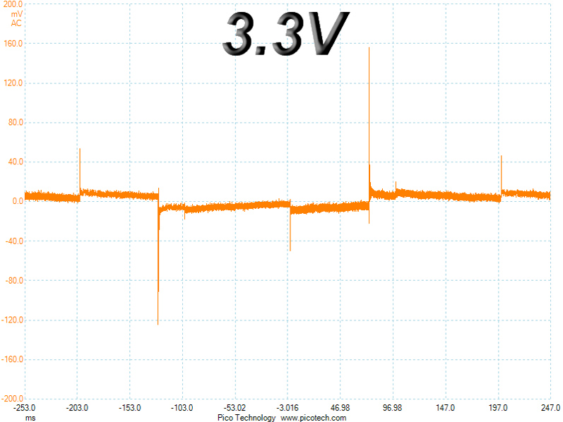
The +12V rail's transient response is good enough for this PSU's capacity. The 5V and 5VSB rails perform quite well, while the deviations at 3.3V should be lower, but Andyson couldn't push the DC-DC converters any more for a better transient response on this rail, and we didn't want to lose performance in another area, which had us accept the result since this rail barely drops below 3.2V when the transient load is applied.
Below are the oscilloscope screenshots we took during Advanced Transient Response testing.
Transient Response at 20% Load
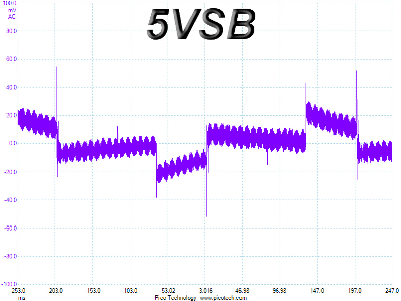
Transient Response at 50% Load
Turn-On Transient Tests
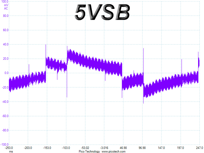
We measure the response of the PSU in simpler scenarios of transient load—during the power-on phase of the PSU—in the next set of tests. In the first test, we turn the PSU off, dial the maximum current the 5VSB can output, and then switch on the PSU. In the second test, we dial the maximum load +12V can handle and start the PSU while the PSU is in standby mode. In the last test, while the PSU is completely switched off (we cut off power or switch the PSU off by flipping its on/off switch), we dial the maximum load the +12V rail can handle before switching the PSU on through the loader and restoring power. The ATX specification states that recorded spikes on all rails should not exceed 10% of their nominal values (e.g., +10% for 12V is 13.2V and 5.5V for 5V).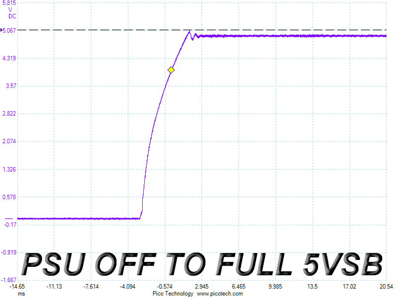
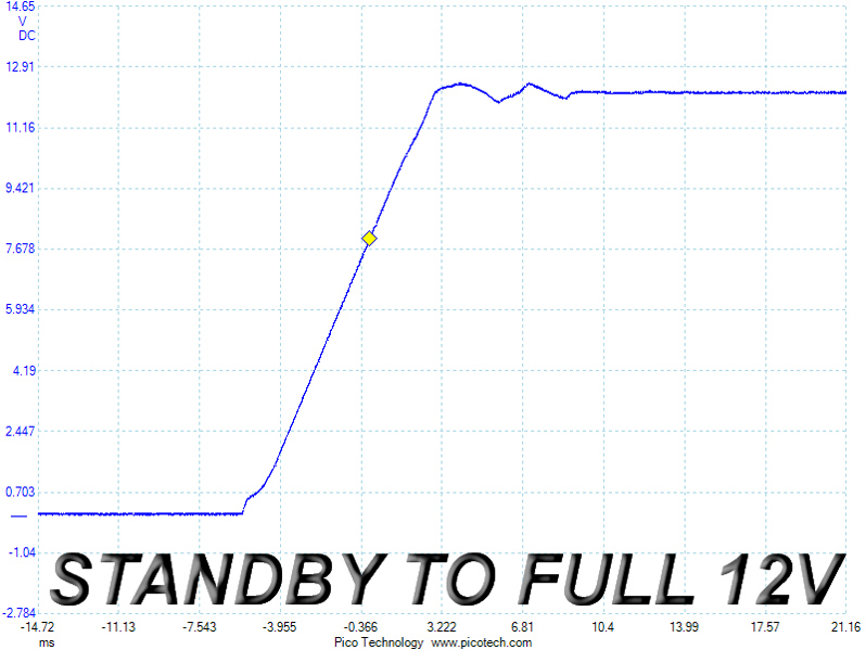
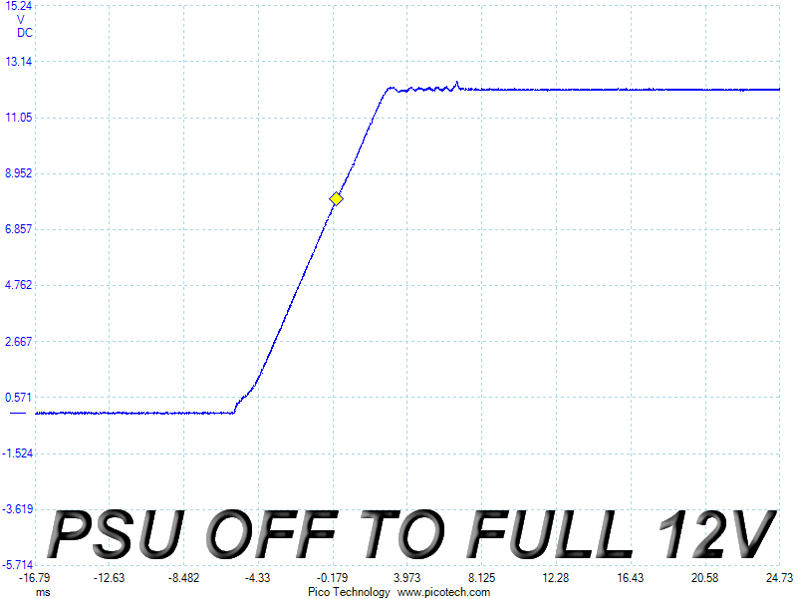
There is a tiny voltage overshoot at 5VSB, a small wave during the second test, and a minor spike in the third test. Surely not perfect, these results are completely satisfactory - even when it comes to meeting our high demands.
Jul 15th, 2025 16:24 CDT
change timezone
Latest GPU Drivers
New Forum Posts
- No offense, here are some things that bother me about your understanding of fans. (145)
- Stupid things one has done with hardware (65)
- RTX 5070 discussion (11)
- I would give anything for Valve's Steam to have an option to disable the Big Picture Mode button. How many times have I accidently clicked it, fml (52)
- Choosing the right motherboard (6)
- Solidigm NVMe Custom Modded Driver for All NVMe Brands SSDs & Any NVMe SSDs (229)
- Recommend me a decent budget card :) (33)
- What's your latest tech purchase? (24278)
- TOS 6 on Ugreen NAS (0)
- Folding Pie and Milestones!! (9620)
Popular Reviews
- MSI GeForce RTX 5060 Gaming OC Review
- Our Visit to the Hunter Super Computer
- Lexar NM1090 Pro 4 TB Review
- SilverStone SETA H2 Review
- NVIDIA GeForce RTX 5050 8 GB Review
- Fractal Design Epoch RGB TG Review
- Sapphire Radeon RX 9060 XT Pulse OC 16 GB Review - An Excellent Choice
- AMD Ryzen 7 9800X3D Review - The Best Gaming Processor
- Upcoming Hardware Launches 2025 (Updated May 2025)
- Corsair FRAME 5000D RS Review
TPU on YouTube
Controversial News Posts
- Intel's Core Ultra 7 265K and 265KF CPUs Dip Below $250 (288)
- Some Intel Nova Lake CPUs Rumored to Challenge AMD's 3D V-Cache in Desktop Gaming (140)
- AMD Radeon RX 9070 XT Gains 9% Performance at 1440p with Latest Driver, Beats RTX 5070 Ti (131)
- NVIDIA Launches GeForce RTX 5050 for Desktops and Laptops, Starts at $249 (122)
- NVIDIA GeForce RTX 5080 SUPER Could Feature 24 GB Memory, Increased Power Limits (115)
- Microsoft Partners with AMD for Next-gen Xbox Hardware (105)
- Intel "Nova Lake‑S" Series: Seven SKUs, Up to 52 Cores and 150 W TDP (100)
- NVIDIA DLSS Transformer Cuts VRAM Usage by 20% (99)