 27
27
Corsair HXi Series 1000 W Review
Ripple Measurements »Advanced Transient Response Tests
In these tests, we monitor the response of the PSU in two different scenarios. First, a transient load (10 A at +12V, 5 A at 5V, 5 A at 3.3V, and 0.5 A at 5VSB) is applied to the PSU for 200 ms while the latter is working at 20% load. In the second scenario, the PSU, while working at 50% load, is hit by the same transient load. In both tests, we measure the voltage drops the transient load causes using our oscilloscope. The voltages should remain within the regulation limits defined by the ATX specification. We must stress here that these tests are crucial since they simulate transient loads a PSU is very likely to handle (e.g., booting a RAID array, an instant 100% load of CPU/VGAs, etc.). We call these tests "Advanced Transient Response Tests", and they are designed to be very tough to master, especially for a PSU with a capacity below 500 W.| Advanced Transient Response 20% | ||||
|---|---|---|---|---|
| Voltage | Before | After | Change | Pass/Fail |
| 12 V | 12.052V | 11.968V | 0.70% | Pass |
| 5 V | 5.022V | 4.959V | 1.25% | Pass |
| 3.3 V | 3.300V | 3.225V | 2.27% | Pass |
| 5VSB | 5.006V | 4.956V | 1.00% | Pass |
| Advanced Transient Response 50% | ||||
|---|---|---|---|---|
| Voltage | Before | After | Change | Pass/Fail |
| 12 V | 12.005V | 11.955V | 0.42% | Pass |
| 5 V | 5.031V | 4.976V | 1.09% | Pass |
| 3.3 V | 3.309V | 3.225V | 2.54% | Pass |
| 5VSB | 5.009V | 4.966V | 0.86% | Pass |
In the first test, the +12V rail suffered a higher voltage drop than in the second and normally tougher test. However, our experience tells us that this is typical of a PSU with an LLC resonant converter. Overall, deviations were kept low on both rails, and the other rails performed incredibly well to boot.
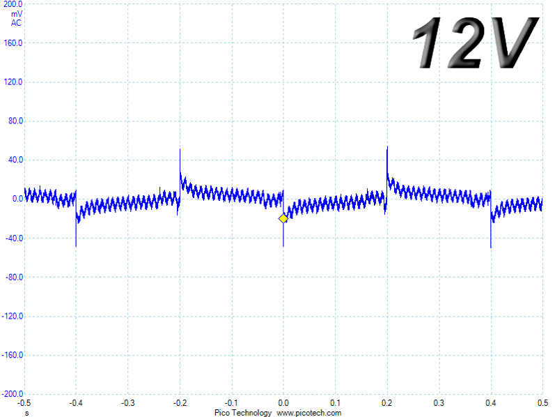
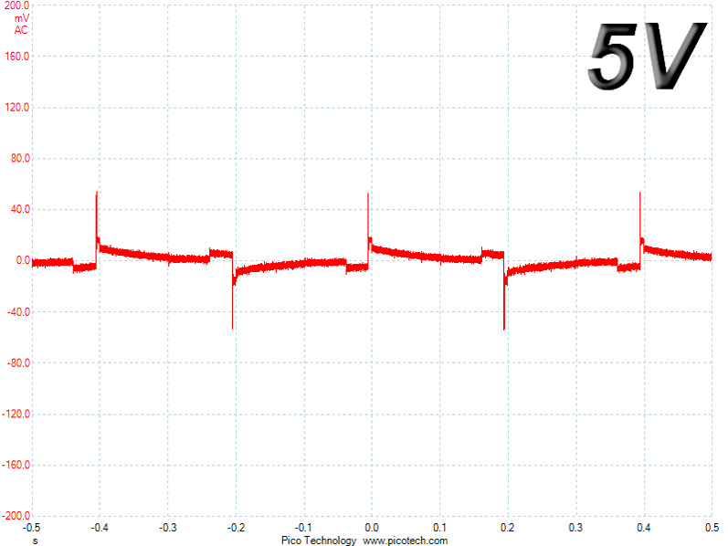
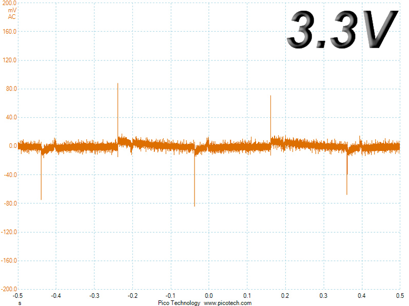
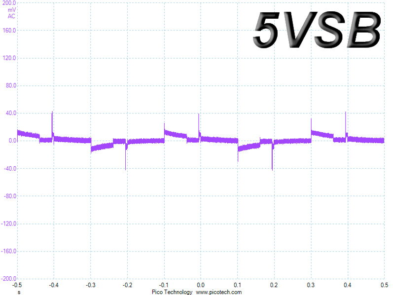
Below are the oscilloscope screenshots we took during Advanced Transient Response testing.
Transient Response at 20% Load
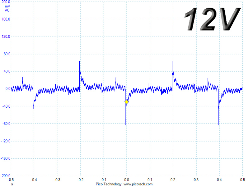
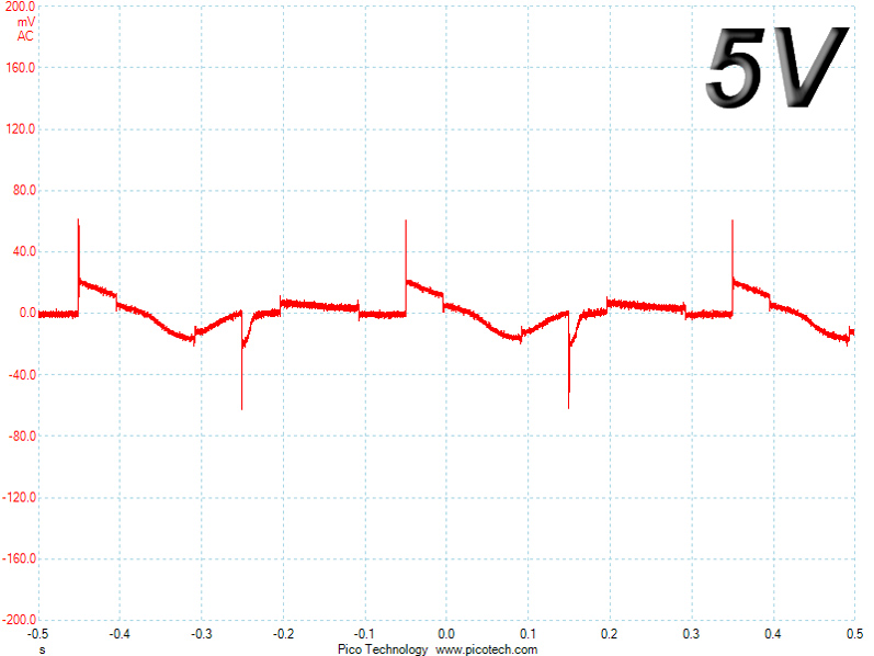
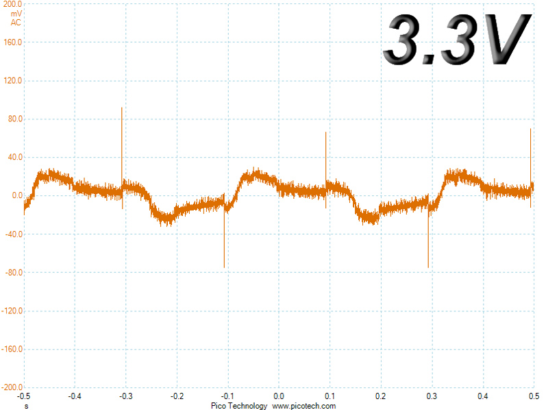
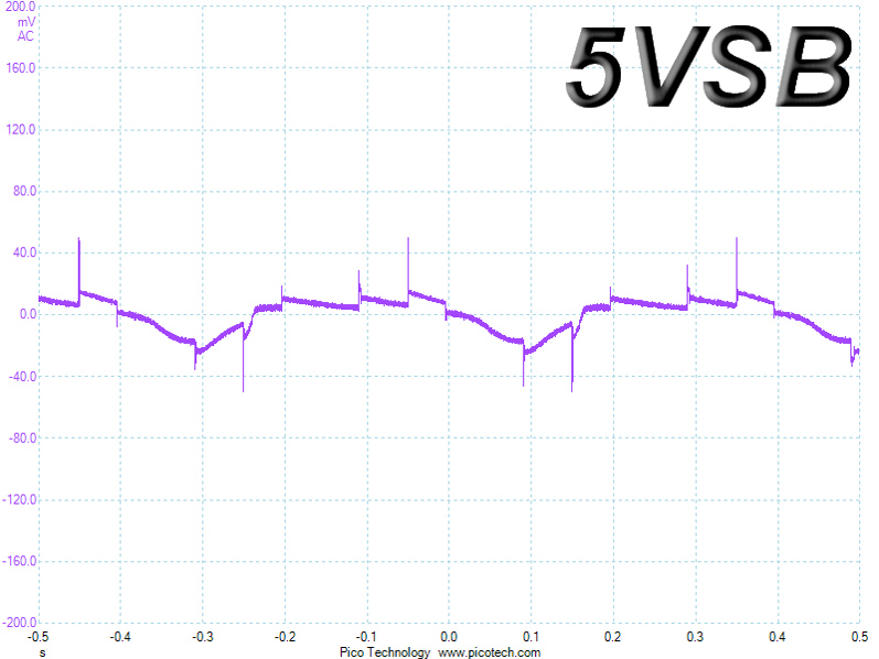
Transient Response at 50% Load
Turn-On Transient Tests
We measure the response of the PSU in simpler scenarios of transient load—during the power-on phase of the PSU—in the next set of tests. In the first test, we turn the PSU off, dial the maximum current the 5VSB can output, and then switch on the PSU. In the second test, we dial the maximum load +12V can handle and start the PSU while the PSU is in standby mode. In the last test, while the PSU is completely switched off (we cut off power or switch the PSU off by flipping its on/off switch), we dial the maximum load the +12V rail can handle before switching the PSU on from the loader and restoring power. The ATX specification states that recorded spikes on all rails should not exceed 10% of their nominal values (e.g., +10% for 12V is 13.2V and 5.5V for 5V).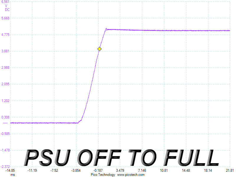
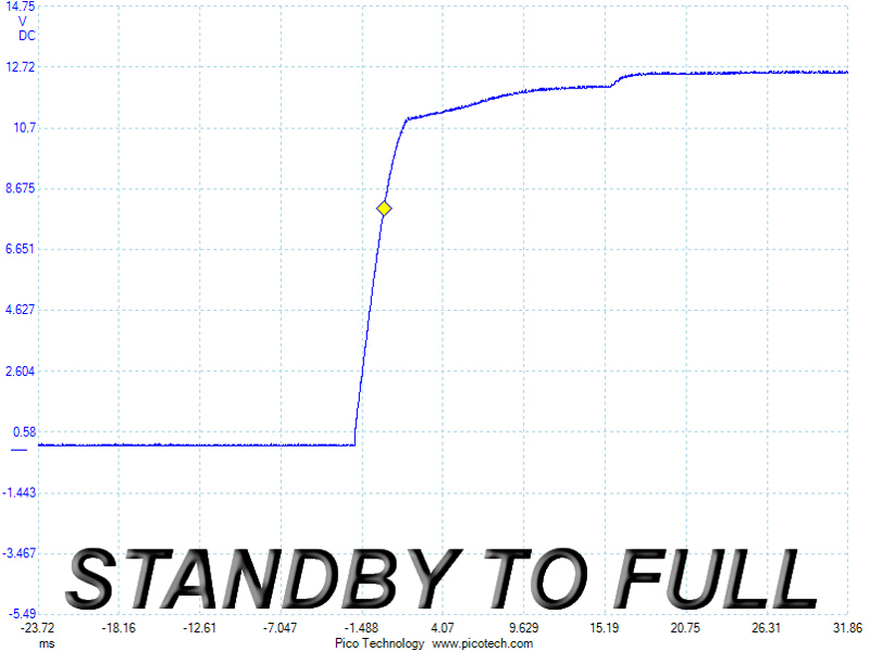
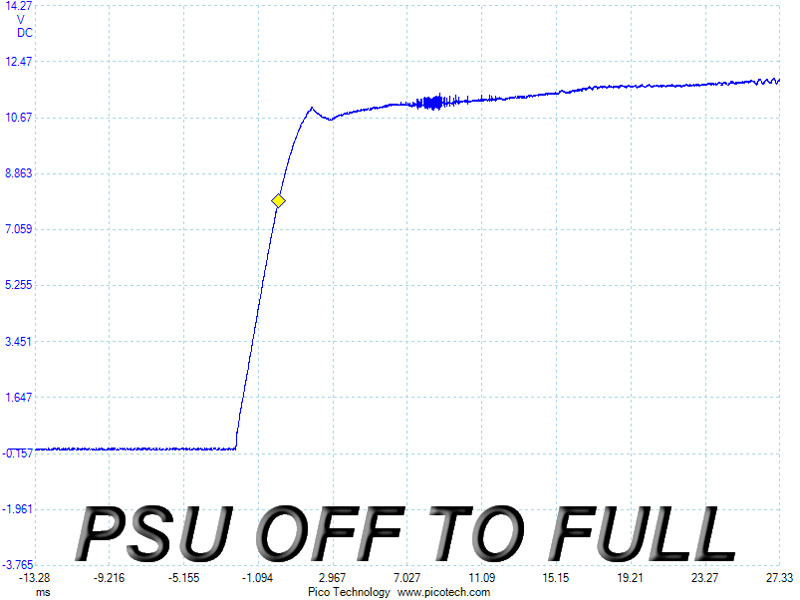
We noticed a tiny voltage overshoot at 5VSB, which is nothing to worry about, and the voltage took a few milliseconds to reach its nominal value in the other two tests. We also noticed a small voltage overshoot and a short period with excessive ripple in the last test. All in all, we expected the HX1000i to perform a little better in these tests which usually don't trouble us so long as such a high-end platform is our test subject.
Jul 3rd, 2025 22:18 CDT
change timezone
Latest GPU Drivers
New Forum Posts
- GPU-Z Display Bug via DP 2.1? (6)
- [GPU-Z Test Build] New Kernel Driver, Everyone: Please Test (35)
- What Windows is overall the best to you and why? (269)
- How do you view TPU & the internet in general? (With poll) (58)
- HP Zbook 15 G2 GPU Upgrade (12)
- Will you buy a RTX 5090? (610)
- What phone you use as your daily driver? And, a discussion of them. (1756)
- What would you buy? (51)
- A Final Fantasy IX Reminiscence - My love letter and homage to one of the best stories ever told (90)
- GravityMark v1.89 GPU Benchmark (309)
Popular Reviews
- ASUS ROG Crosshair X870E Extreme Review
- Crucial T710 2 TB Review - Record-Breaking Gen 5
- Fractal Design Scape Review - Debut Done Right
- PowerColor ALPHYN AM10 Review
- Sapphire Radeon RX 9060 XT Pulse OC 16 GB Review - An Excellent Choice
- Upcoming Hardware Launches 2025 (Updated May 2025)
- AMD Ryzen 7 9800X3D Review - The Best Gaming Processor
- Sapphire Radeon RX 9070 XT Nitro+ Review - Beating NVIDIA
- SCHENKER KEY 18 Pro (E25) Review - Top-Tier Contender
- AVerMedia CamStream 4K Review
TPU on YouTube
Controversial News Posts
- Intel's Core Ultra 7 265K and 265KF CPUs Dip Below $250 (288)
- NVIDIA Grabs Market Share, AMD Loses Ground, and Intel Disappears in Latest dGPU Update (212)
- Some Intel Nova Lake CPUs Rumored to Challenge AMD's 3D V-Cache in Desktop Gaming (140)
- NVIDIA GeForce RTX 5080 SUPER Could Feature 24 GB Memory, Increased Power Limits (115)
- Microsoft Partners with AMD for Next-gen Xbox Hardware (105)
- NVIDIA Launches GeForce RTX 5050 for Desktops and Laptops, Starts at $249 (105)
- Intel "Nova Lake‑S" Series: Seven SKUs, Up to 52 Cores and 150 W TDP (100)
- NVIDIA DLSS Transformer Cuts VRAM Usage by 20% (97)