 12
12
Corsair Professional Series HX1050 Review
Value & Conclusion »Ripple Measurements
In the following table you will find the ripple levels that we measured on the main rails of HX1050. According to ATX specification the limits are 120 mV (+12V) and 50 mV (5V & 3.3V).| Ripple Measurements | ||||
|---|---|---|---|---|
| Test | 12 V | 5 V | 3.3 V | Pass/Fail |
| 20% Load | 7.4 mV | 7.6 mV | 6.8 mV | Pass |
| 40% Load | 11.2 mV | 9.2 mV | 8.2 mV | Pass |
| 50% Load | 13.6 mV | 9.6 mV | 8.8 mV | Pass |
| 60% Load | 16.4 mV | 10.8 mV | 9.4 mV | Pass |
| 80% Load | 23.2 mV | 12.8 mV | 11.6 mV | Pass |
| 100% Load | 32.4 mV | 14.8 mV | 14.2 mV | Pass |
| Crossload 1 | 9.6 mV | 8.8 mV | 7.8 mV | Pass |
| Crossload 2 | 31.2 mV | 15.8 mV | 12.8 mV | Pass |
Overall ripple/noise suppression on all rails is superb! Even at 100% load, ripple at +12V is almost a quarter of the limit and on the minor rails it is less than one third of the respective limit. It is clear that Corsair/CWT found the secret formula that eliminates ripple, even at above 1000W loads.
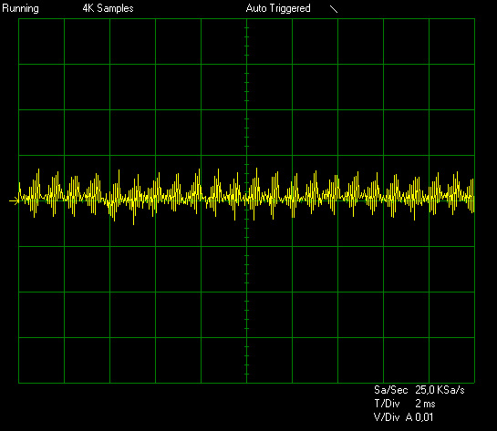
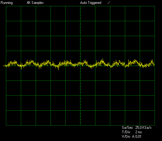
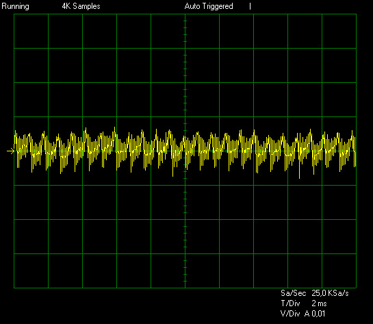
Ripple at Full Load
In the following oscilloscope screenshots you can see the AC ripple and noise that the main rails registered (+12V, 5V, 3.3V). The bigger the fluctuations on the oscilloscope's screen the bigger the ripple/noise. We set 0.01 V/Div (each vertical division/box equals to 0.01V) as standard but sometimes we are forced to use 0.02 V/Div, meaning that the fluctuations will look smaller but actually this wont be the case. For the first screenshot we used 0.02 V/Div, so actually the registered ripple is much bigger than it seems (compared to the other screenshots where 0.01 V/Div was used).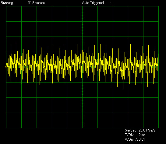

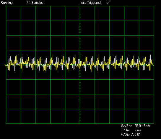
Ripple at Crossload 1
For the first screenshot we used again 0.02 V/Div. The order of images is +12V, 5V and 3.3V.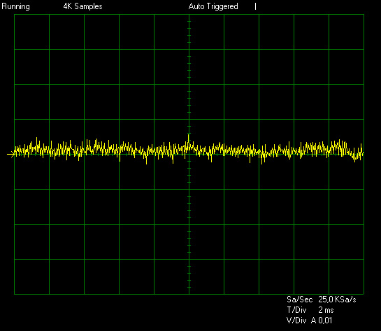

Ripple at Crossload 2
For the first screenshot we used again 0.02 V/Div. As above the order of images is +12V, 5V and 3.3V.
Jul 12th, 2025 01:16 CDT
change timezone
Latest GPU Drivers
New Forum Posts
- Will you buy a RTX 5090? (642)
- 'NVIDIA App' not usable offline? (8)
- Can you guess Which game it is? (222)
- What are you playing? (23920)
- RX 9070 XT freezing/locking up only on desktop, anyone else? (43)
- NVIDIA RTX PRO 6000 Workstation Runs Much Hotter Than 5090 FE (22)
- Quick charging your USB devicesUSB 3.2 Gen 2x2 Type-C® front-panel. (1)
- GTX 1050 GPU Owners Club (12)
- ASUS ProArt GeForce RTX 4060 Ti OC Edition 16GB GDDR6 Gaming - nvflash64 VBIOS mismatch (2)
- No offense, here are some things that bother me about your understanding of fans. (33)
Popular Reviews
- Fractal Design Epoch RGB TG Review
- Corsair FRAME 5000D RS Review
- Lexar NM1090 Pro 4 TB Review
- NVIDIA GeForce RTX 5050 8 GB Review
- NZXT N9 X870E Review
- Sapphire Radeon RX 9060 XT Pulse OC 16 GB Review - An Excellent Choice
- AMD Ryzen 7 9800X3D Review - The Best Gaming Processor
- Upcoming Hardware Launches 2025 (Updated May 2025)
- Our Visit to the Hunter Super Computer
- Chieftec Iceberg 360 Review
TPU on YouTube
Controversial News Posts
- Intel's Core Ultra 7 265K and 265KF CPUs Dip Below $250 (288)
- Some Intel Nova Lake CPUs Rumored to Challenge AMD's 3D V-Cache in Desktop Gaming (140)
- AMD Radeon RX 9070 XT Gains 9% Performance at 1440p with Latest Driver, Beats RTX 5070 Ti (131)
- NVIDIA Launches GeForce RTX 5050 for Desktops and Laptops, Starts at $249 (119)
- NVIDIA GeForce RTX 5080 SUPER Could Feature 24 GB Memory, Increased Power Limits (115)
- Microsoft Partners with AMD for Next-gen Xbox Hardware (105)
- Intel "Nova Lake‑S" Series: Seven SKUs, Up to 52 Cores and 150 W TDP (100)
- NVIDIA DLSS Transformer Cuts VRAM Usage by 20% (97)