 13
13
Cougar LX Series 600 W Review
Ripple Measurements »Advanced Transient Response Tests
In these tests, we monitor the response of the PSU in two different scenarios. First, a transient load (10 A at +12V, 5 A at 5V, 5 A at 3.3V, and 0.5 A at 5VSB) is applied to the PSU for 200 ms while the latter is working at 20% load. In the second scenario, the PSU, while working at 50% load, is hit by the same transient load. In both tests, we measure the voltage drops the transient load causes using our oscilloscope. The voltages should remain within the regulation limits defined by the ATX specification. We must stress here that these tests are crucial since they simulate transient loads a PSU is very likely to handle (e.g., booting a RAID array, an instant 100% load of CPU/VGAs, etc.). We call these tests Advanced Transient Response tests, and they are designed to be very tough to master, especially for PSUs with a capacity below 500 W.| Advanced Transient Response 20% | ||||
|---|---|---|---|---|
| Voltage | Before | After | Change | Pass/Fail |
| 12 V | 12.108V | 11.989V | 0.98% | Pass |
| 5 V | 5.016V | 4.848V | 3.35% | Pass |
| 3.3 V | 3.321V | 3.149V | 5.18% | Pass |
| 5VSB | 5.051V | 4.984V | 1.33% | Pass |
| Advanced Transient Response 50% | ||||
|---|---|---|---|---|
| Voltage | Before | After | Change | Pass/Fail |
| 12 V | 12.037V | 11.924V | 0.94% | Pass |
| 5 V | 4.955V | 4.793V | 3.27% | Pass |
| 3.3 V | 3.275V | 3.105V | 5.19% | Fail |
| 5VSB | 4.993V | 4.917V | 1.52% | Pass |
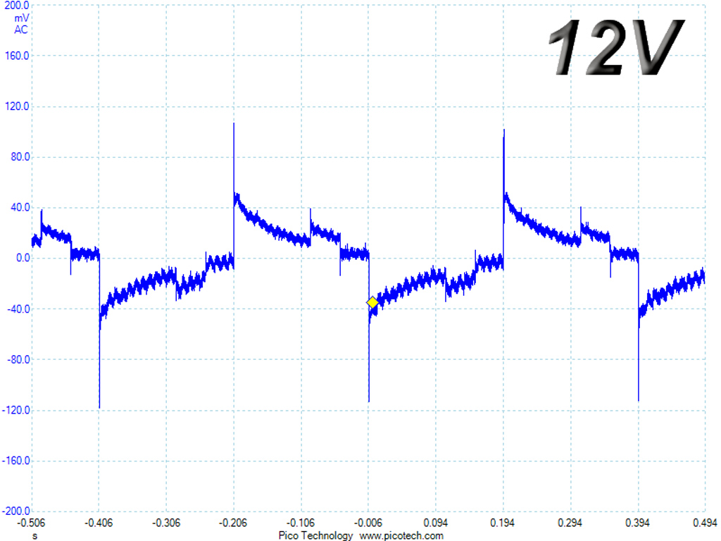
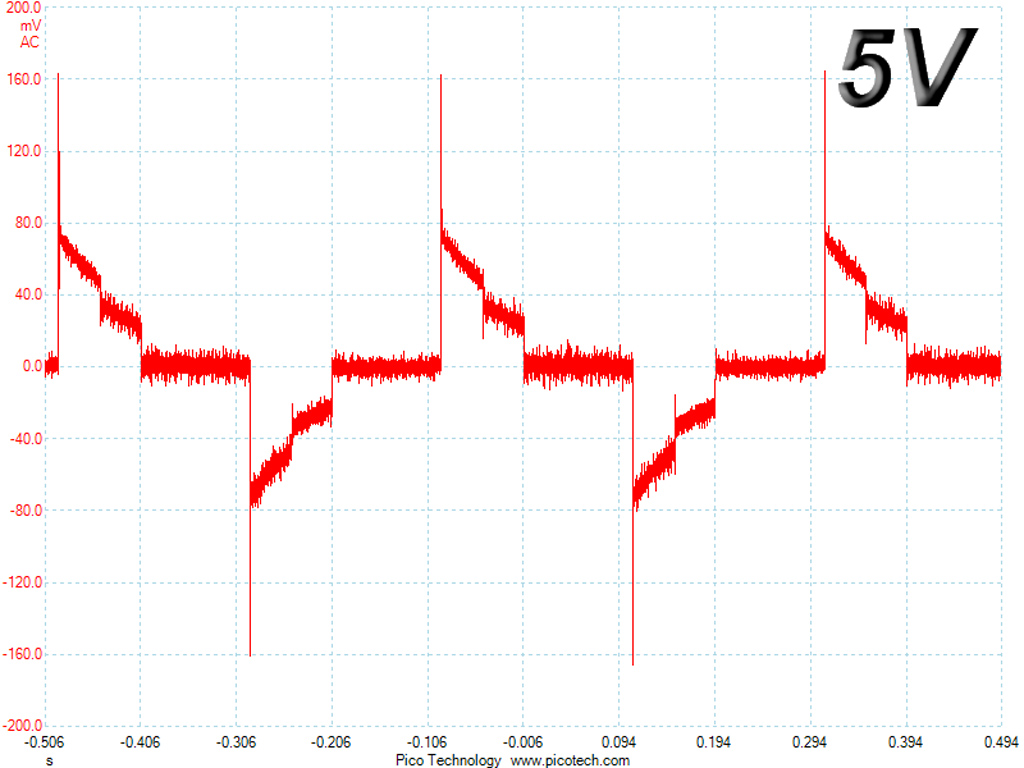
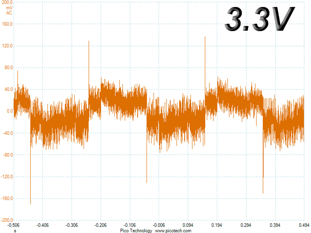
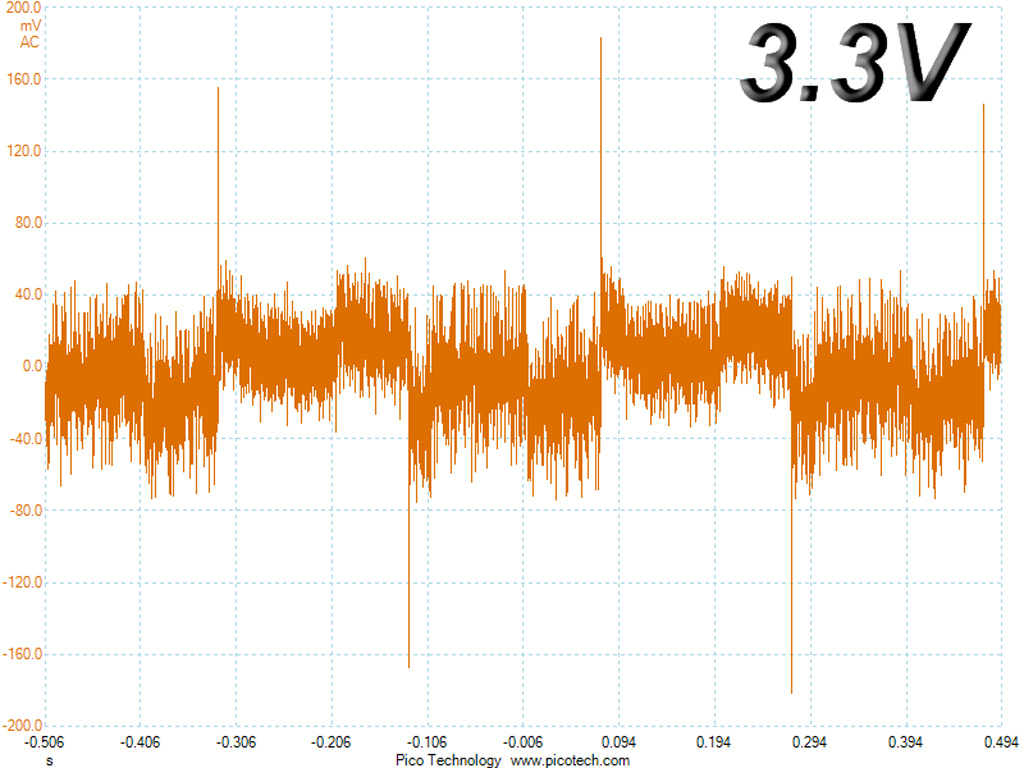
The +12V rail stayed within 1% in both tests, which is a pretty good result for this category. The 5V rail deviated by more, but the 5VSB rail performed very well. The 3.3V rail registered the worst performance by failing to keep its load regulation within the ATX specification's requirements in the second test.
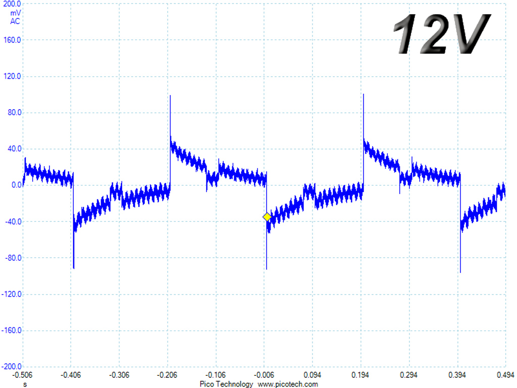
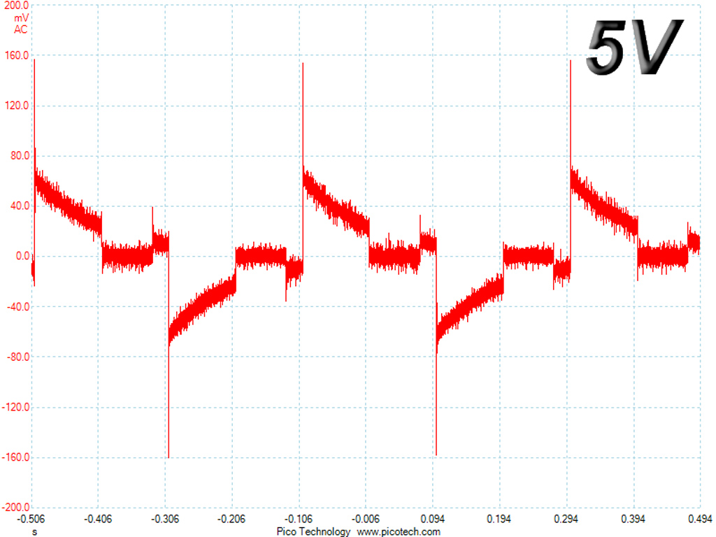
Below are the oscilloscope screenshots we took during Advanced Transient Response testing.
Transient Response at 20% Load
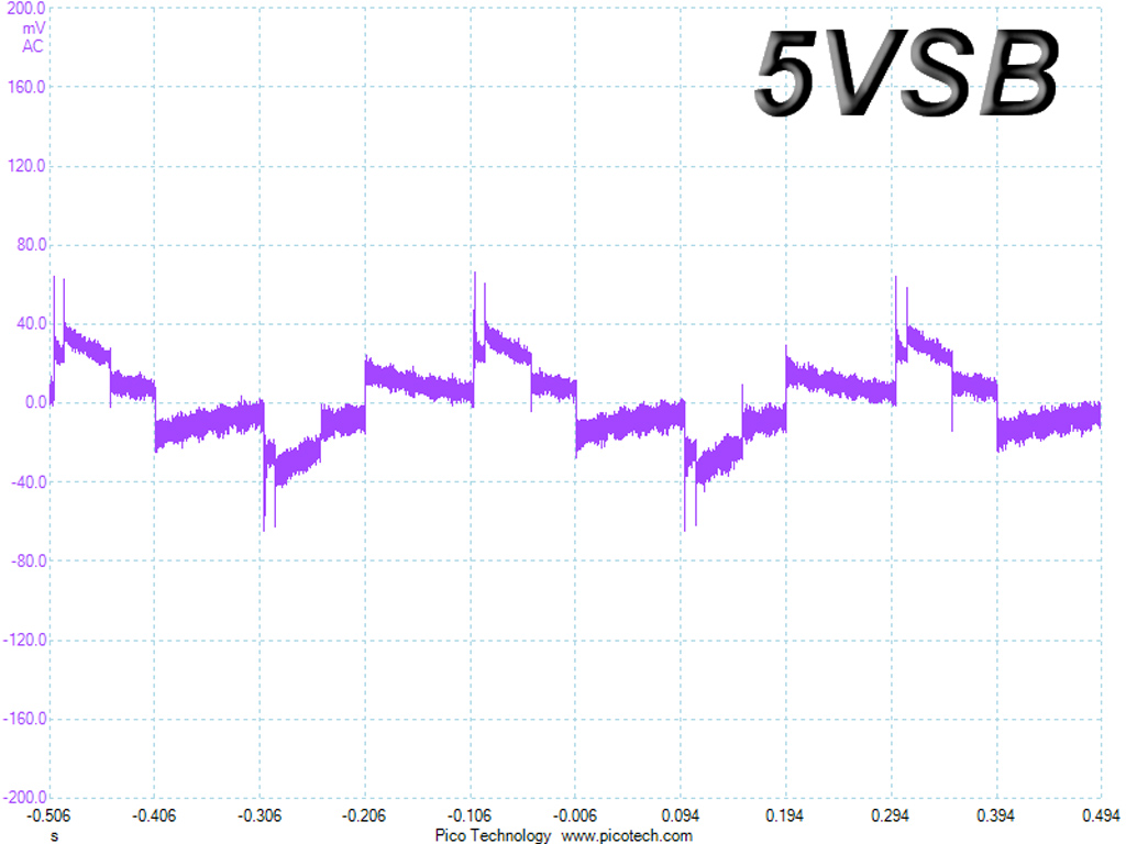
Transient Response at 50% Load
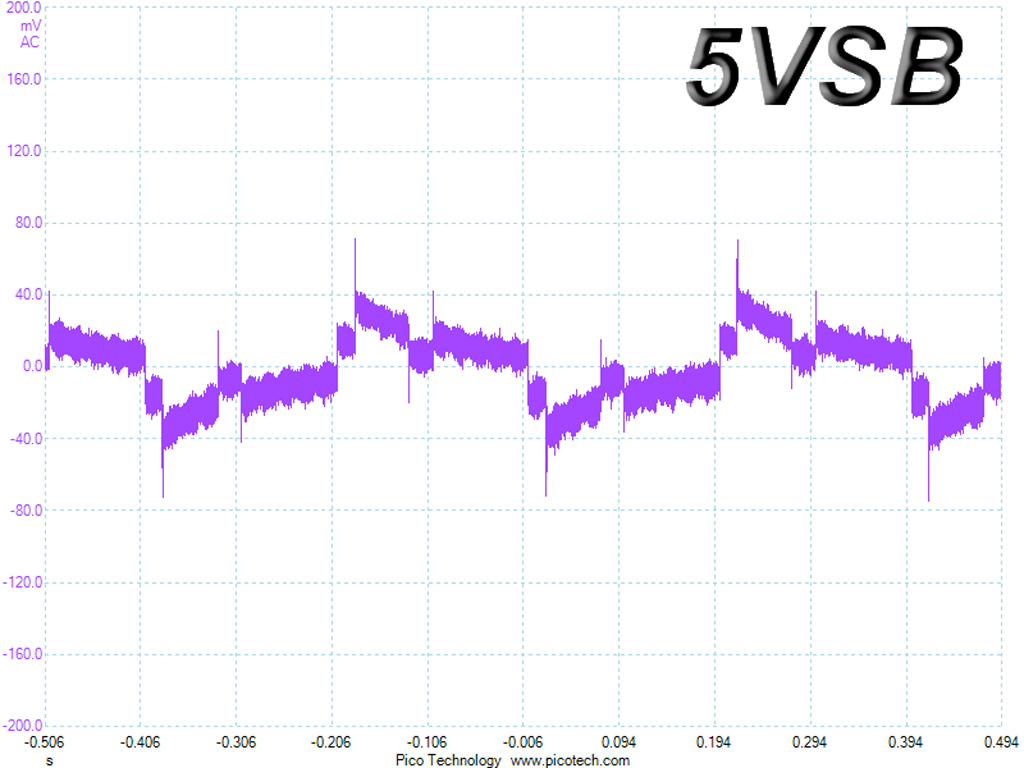
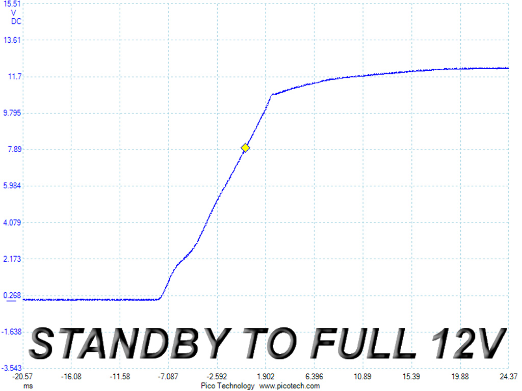
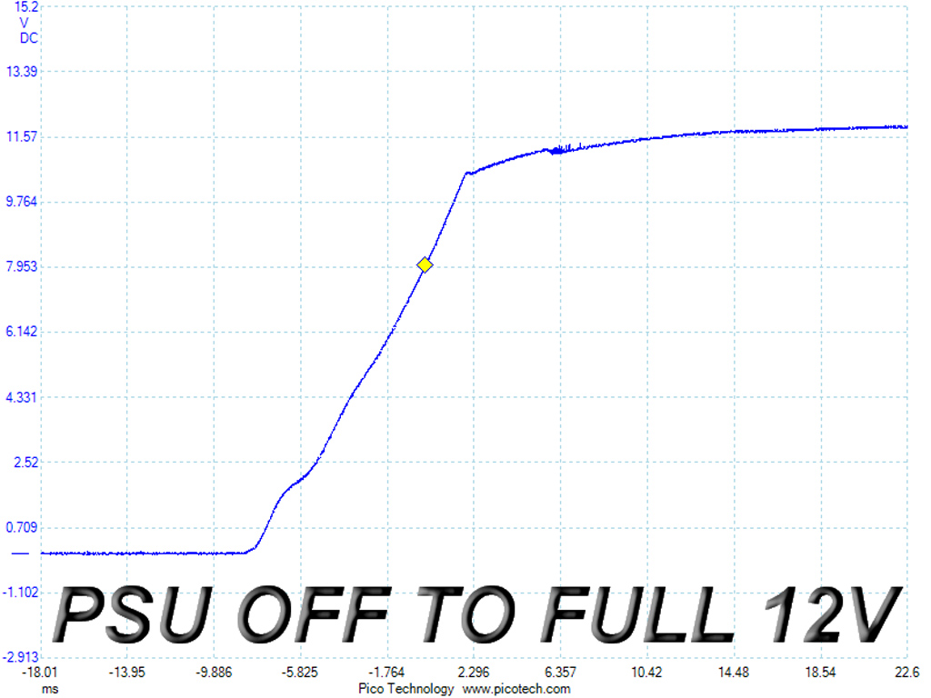
Turn-On Transient Tests
We measure the response of the PSU in simpler scenarios of transient load—during the power-on phase of the PSU—in these tests. In the first test, we turn the PSU off, dial the maximum current 5VSB can output, and switch on the PSU. In the second test, we dial the maximum load +12V can handle and start the PSU while the PSU is in standby mode. In the last test, we dial the maximum load the +12V rail can handle in while the PSU is completely switched off (we cut off power or switch the PSU off by flipping its on/off switch), before switching the PSU on through the loader and restoring power. The ATX specification states that recorded spikes on all rails should not exceed 10% of their nominal values (e.g., +10% for 12V is 13.2V and 5.5V for 5V).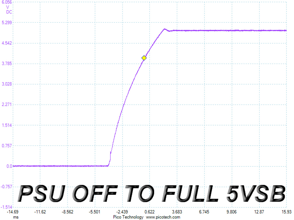
A tiny spike at 5VSB and a very short period with increased ripple aren't enough to spoil the good overall picture these tests paint.
Jul 18th, 2025 19:22 CDT
change timezone
Latest GPU Drivers
New Forum Posts
- Anime Nation (13052)
- What's your latest tech purchase? (24305)
- AI Job Losses: let's count the losses up, total losses to AI so far 94,000 and counting (35)
- lower score 5070Ti after replacing the PSU (0)
- TPU's Nostalgic Hardware Club (20539)
- 3DMARK "LEGENDARY" (329)
- Hatsune Miku x ASUS TUF Gaming Build (67)
- Ferrari themed mod cont. 4070s repaste (7)
- Stalker 2 is looking great. (213)
- Share your CPU-X Benchmarks! (6)
Popular Reviews
- MSI GeForce RTX 5060 Gaming OC Review
- Razer Blade 16 (2025) Review - Thin, Light, Punchy, and Efficient
- Thermal Grizzly WireView Pro Review
- Pulsar X2 Crazylight Review
- SilverStone SETA H2 Review
- AVerMedia Live Gamer Ultra S (GC553Pro) Review
- Upcoming Hardware Launches 2025 (Updated May 2025)
- Sapphire Radeon RX 9060 XT Pulse OC 16 GB Review - An Excellent Choice
- NVIDIA GeForce RTX 5050 8 GB Review
- Our Visit to the Hunter Super Computer
TPU on YouTube
Controversial News Posts
- Intel's Core Ultra 7 265K and 265KF CPUs Dip Below $250 (288)
- Some Intel Nova Lake CPUs Rumored to Challenge AMD's 3D V-Cache in Desktop Gaming (140)
- AMD Radeon RX 9070 XT Gains 9% Performance at 1440p with Latest Driver, Beats RTX 5070 Ti (131)
- NVIDIA Launches GeForce RTX 5050 for Desktops and Laptops, Starts at $249 (124)
- NVIDIA GeForce RTX 5080 SUPER Could Feature 24 GB Memory, Increased Power Limits (115)
- Microsoft Partners with AMD for Next-gen Xbox Hardware (105)
- NVIDIA DLSS Transformer Cuts VRAM Usage by 20% (99)
- AMD Sampling Next-Gen Ryzen Desktop "Medusa Ridge," Sees Incremental IPC Upgrade, New cIOD (97)