 8
8
Das Keyboard 5Q Review
Driver »Disassembly

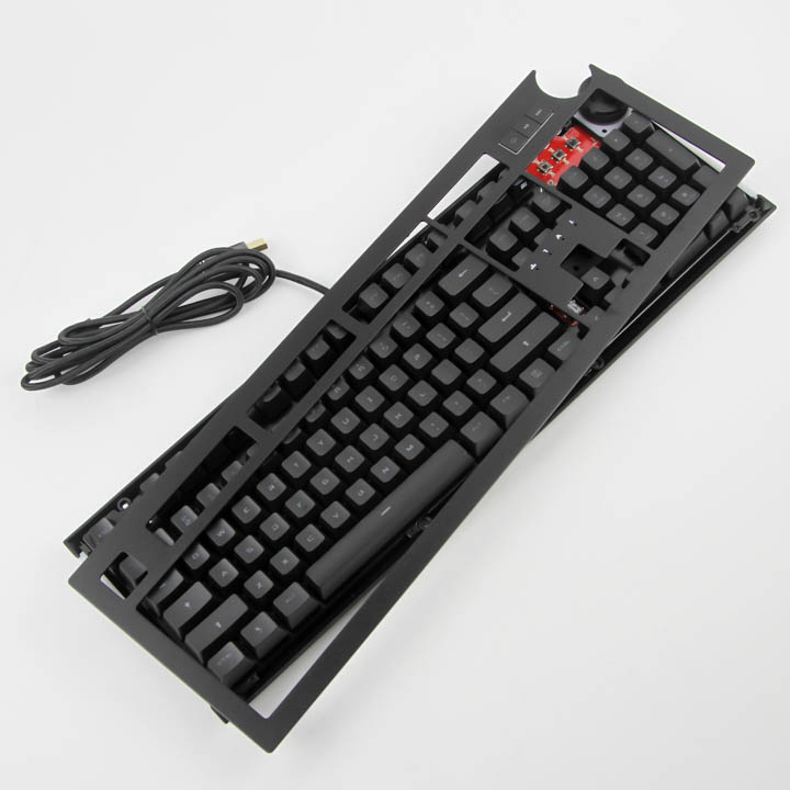
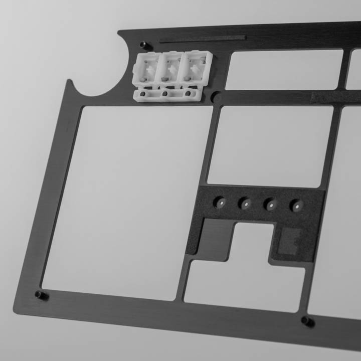
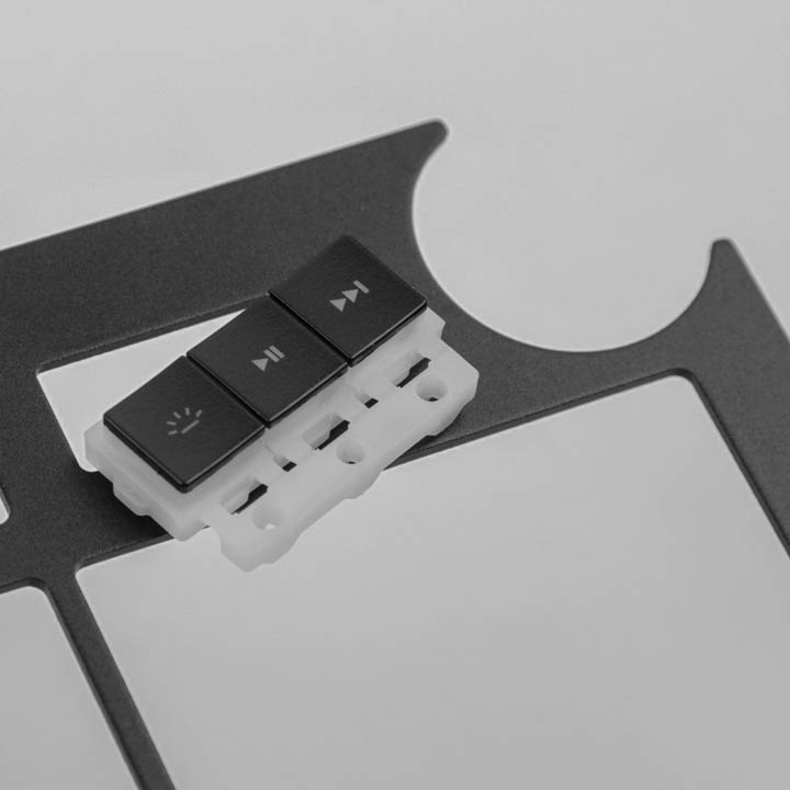
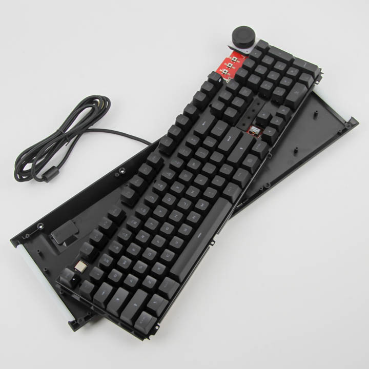
Disassembly of the Das Keyboard 5Q is fairly easy, as with most metal-frame keyboards today. There are eight button head screws accessible from the bottom, which, when removed, allows for the removal of the aluminium frame off the top of the keyboard as seen above. Turning this around, we can see the keycaps for the media keys along with foam pieces to electrically isolate the PCB from the metal to prevent shorting and damage. The keycaps in question can easily be pushed through and out, and we can also better see the cutout to accommodate the volume wheel here.
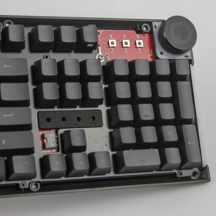
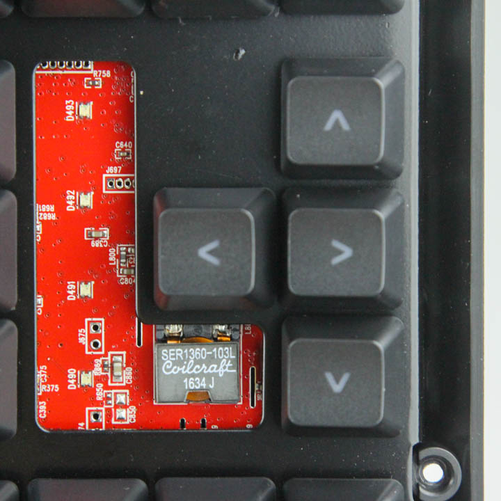
With the frame removed, we can see parts of the PCB exposed, and boy is there a lot to see here! Even before we get to remove the plastic case panel on the bottom, we can see the three switches alongside the volume wheel and associated LEDs in the top-right corner. There is another foam piece in a cutout over the arrow-key cluster for electrical isolation, and underneath is a Coilcraft SER1360 high-current-shielded power inductor. There are more screws to be removed, this time from the front and using a Phillips head screwdriver, to dislodge the case off the rest of the keyboard.
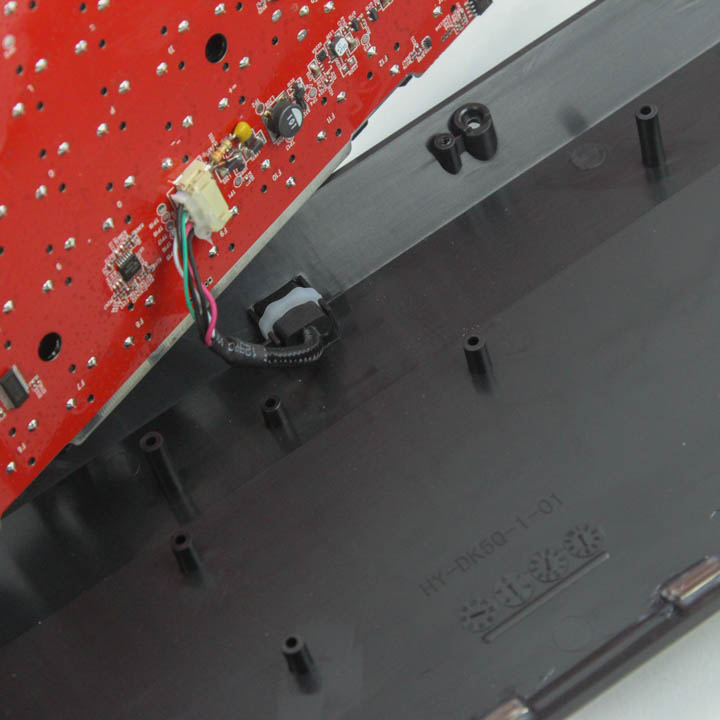
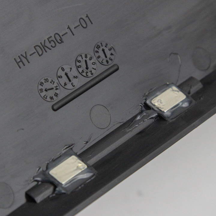
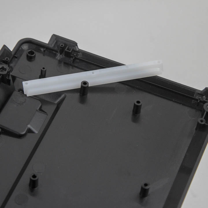
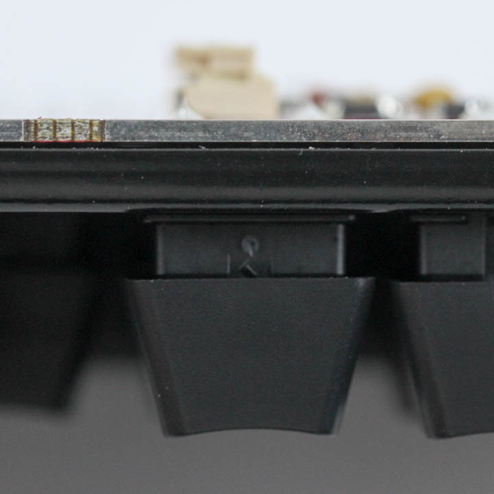
Note that the internal USB cable has to be dislodged off the connector on the PCB first before you can fully separate the two pieces. The case piece is made out of ABS plastic, has two magnets glued in place to use with the wrist rest we saw before, and has two plastic diffuser sections to help with uniform side lighting. The other piece houses the PCB itself, along with a stainless steel plate used for further structural integrity. The switches are soldered into the PCB through the plate and can thus not be removed easily for replacement without de-soldering.
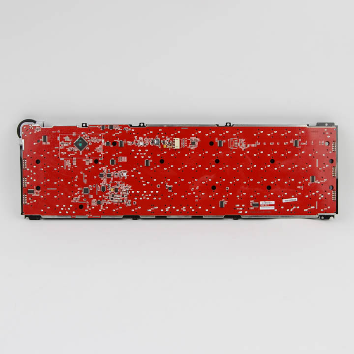
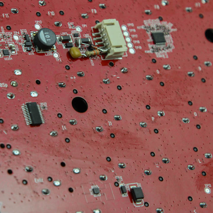
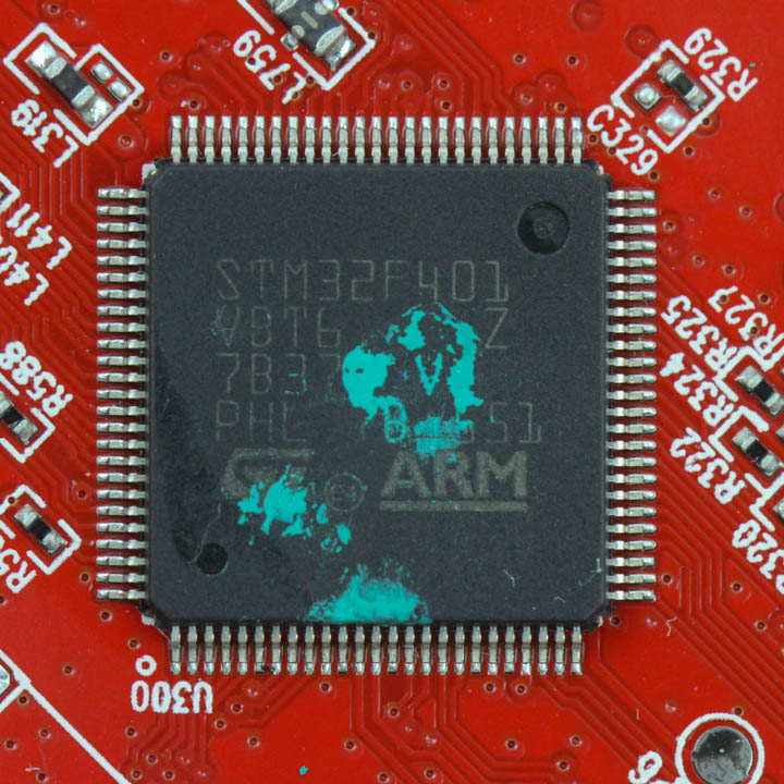
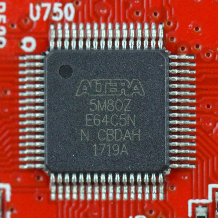
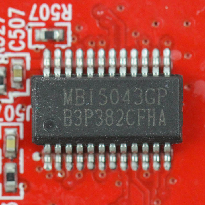
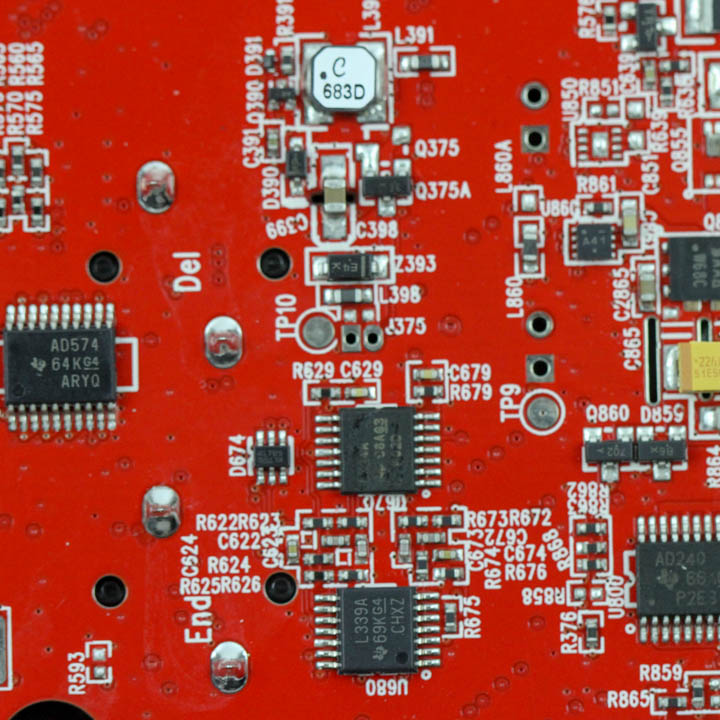
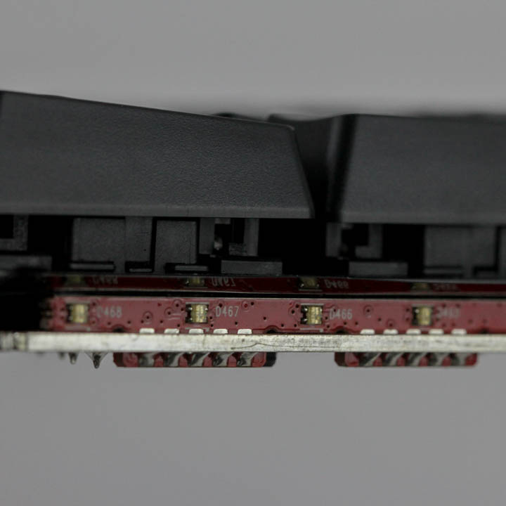
The PCB itself is the most complicated one I have seen used for a PC keyboard to date, including analog control keyboards. There are so many components on both sides of the PCB that the Das Keyboard 5Q comes off more like a concept product to showcase what the company can do, as opposed to a retail product to make money off. Solder quality is really good considering all this as well, so props to them for essentially delivering this knowing that next to no one will ever know. I won't describe every single component because that would take a page or two itself, but onboard is an ARM Cortex STM32F401 32-bit MCU, an Intel/Altera 5M80Z MAX V complex programmable logic device, and multiple Macroblock MBI5043GP 16-bit color PWM, 16-channel LED drivers. Two short daughter PCBs on the sides also host more RGB LEDs for the side lighting we saw signs of before, and everything is soldered on to multi-layered PCBs.
Before we move on, be advised that disassembly will void the warranty and that TechPowerUp is not liable for any damages incurred if you decided to go ahead and do so anyway.
Jul 19th, 2025 00:04 CDT
change timezone
Latest GPU Drivers
New Forum Posts
- What's your latest tech purchase? (24311)
- 9060 XT 8GB or 5060 8GB? (35)
- question for everyone about google play games beta (1)
- Gacha Games - Discussions, Pulls, Updates, etc. (0)
- Idle issue since 5060 ti installed (28)
- Windows 11 General Discussion (6151)
- Have you got pie today? (16795)
- Anime Nation (13054)
- Stalker 2 is looking great. (214)
- Intel Core i9-13980HX Undervolt - Observations and Questions (62)
Popular Reviews
- MSI GeForce RTX 5060 Gaming OC Review
- Razer Blade 16 (2025) Review - Thin, Light, Punchy, and Efficient
- Thermal Grizzly WireView Pro Review
- Pulsar X2 Crazylight Review
- SilverStone SETA H2 Review
- AVerMedia Live Gamer Ultra S (GC553Pro) Review
- Upcoming Hardware Launches 2025 (Updated May 2025)
- Sapphire Radeon RX 9060 XT Pulse OC 16 GB Review - An Excellent Choice
- NVIDIA GeForce RTX 5050 8 GB Review
- Our Visit to the Hunter Super Computer
TPU on YouTube
Controversial News Posts
- Intel's Core Ultra 7 265K and 265KF CPUs Dip Below $250 (288)
- Some Intel Nova Lake CPUs Rumored to Challenge AMD's 3D V-Cache in Desktop Gaming (140)
- AMD Radeon RX 9070 XT Gains 9% Performance at 1440p with Latest Driver, Beats RTX 5070 Ti (131)
- NVIDIA Launches GeForce RTX 5050 for Desktops and Laptops, Starts at $249 (124)
- NVIDIA GeForce RTX 5080 SUPER Could Feature 24 GB Memory, Increased Power Limits (115)
- Microsoft Partners with AMD for Next-gen Xbox Hardware (105)
- NVIDIA DLSS Transformer Cuts VRAM Usage by 20% (99)
- AMD Sampling Next-Gen Ryzen Desktop "Medusa Ridge," Sees Incremental IPC Upgrade, New cIOD (97)