 5
5
Enermax NAXN ADV 650 W Review
Ripple Measurements »Advanced Transient Response Tests
In these tests, we monitor the response of the PSU in two different scenarios. First, a transient load (10 A at +12V, 5 A at 5V, 5 A at 3.3V, and 0.5 A at 5VSB) is applied to the PSU for 200 ms while the latter is working at a 20% load state. In the second scenario, the PSU, while working at 50% load, is hit by the same transient load. In both tests, we measure the voltage drops that the transient load causes using our oscilloscope. The voltages should remain within the regulation limits defined by the ATX specification. We must stress here that the above tests are crucial since they simulate transient loads that a PSU is very likely to handle (e.g., booting a RAID array, an instant 100% load of CPU/VGAs, etc.). We call these tests "Advanced Transient Response Tests", and they are designed to be very tough to master, especially for PSUs with capacities below 500 W.| Advanced Transient Response 20% | ||||
|---|---|---|---|---|
| Voltage | Before | After | Change | Pass/Fail |
| 12 V | 11.860V | 11.431V | 3.62% | Pass |
| 5 V | 5.118V | 4.995V | 2.40% | Pass |
| 3.3 V | 3.347V | 3.182V | 4.93% | Pass |
| 5VSB | 5.043V | 4.988V | 1.09% | Pass |
| Advanced Transient Response 50% | ||||
|---|---|---|---|---|
| Voltage | Before | After | Change | Pass/Fail |
| 12 V | 11.848V | 11.528V | 2.70% | Pass |
| 5 V | 5.076V | 4.960V | 2.29% | Pass |
| 3.3 V | 3.321V | 3.163V | 4.76% | Pass |
| 5VSB | 4.995V | 4.934V | 1.22% | Pass |
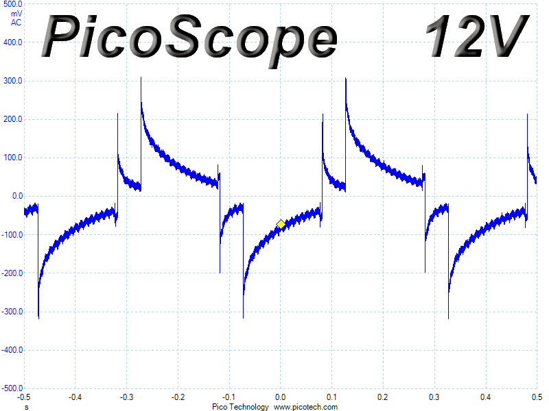
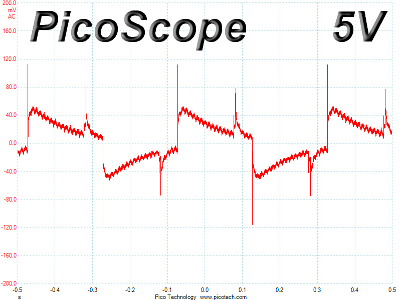
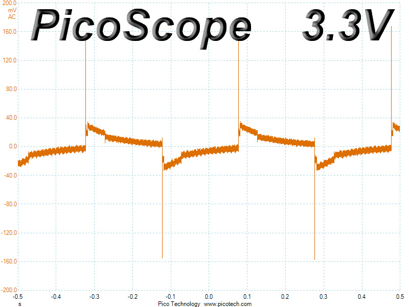
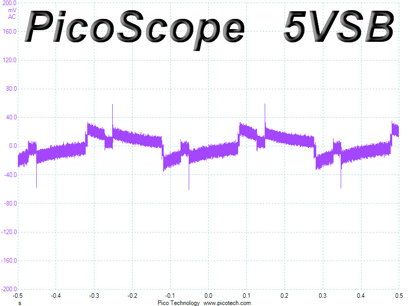
The voltage drops of the +12V rail were pretty high and dangerously close to the lower limit of 11.4 V during the first test. The PSU registered about the same mediocre performance at 3.3V. Voltage drops were small, well-controlled deviations on the 5V and 5VSB rails. The unit's overall performance in these tests was mediocre.
Below, you will find the oscilloscope screenshots we took during Advanced Transient Response Testing.
Transient Response at 20% Load
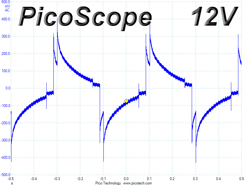
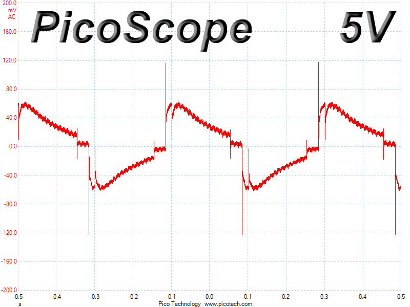
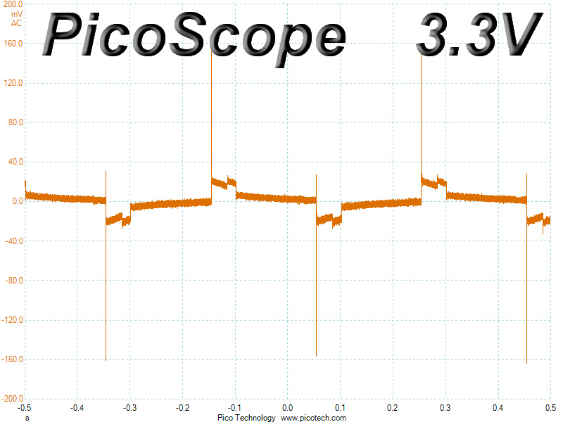
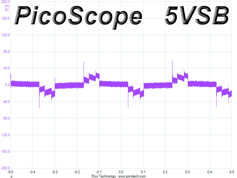
Transient Response at 50% Load
Turn-On Transient Tests
We measure the response of the PSU in simpler scenarios of transient loads—during the power-on phase of the PSU—in the next set of tests. In the first test, we turn the PSU off, dial the maximum current that the 5VSB can output, and then switch on the PSU. In the second test, we dial the maximum load that +12V can handle and start the PSU while the PSU is in standby mode. In the last test, while the PSU is completely switched off (we cut off power or switch off the PSU's on/off switch), we dial the maximum load that the +12V rail can handle before switching the PSU on from the loader and restoring power. The ATX specification states that recorded spikes on all rails should not exceed 10% of their nominal values (e.g., +10% for 12V is 13.2V and 5.5V for 5V).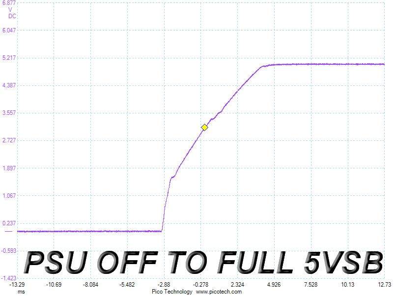
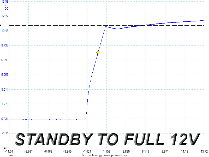
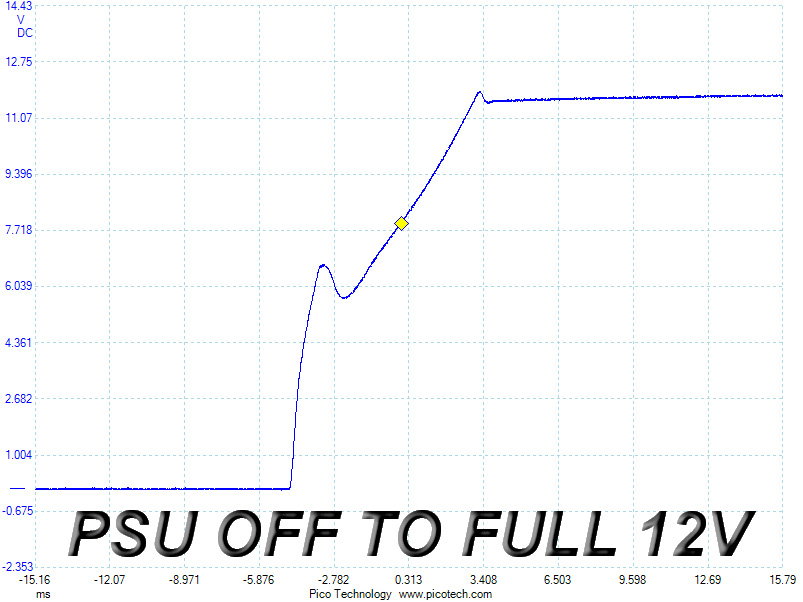
The slope is fine at 5VSB, but the first test at +12V registers a voltage overshoot; however, it is below even the rail's normal voltage. The slope of the last test is not smooth. Not only does it dive at around 6.5 V but it also registers a voltage overshoot.
Jul 14th, 2025 19:01 CDT
change timezone
Latest GPU Drivers
New Forum Posts
- No offense, here are some things that bother me about your understanding of fans. (119)
- AMD 7Ghz? This keeps popping up on my feeds! (23)
- Cryptocoin Value and Market Trend Discussion (1657)
- System stutters with Ryzen 7 9800X3D. (1)
- Dual GPU Motherboard for home VFX (1)
- i7 2860QM how to raise power limit? (24)
- Large Format Plotter WiFi / LAN issue on Laptop (2)
- Is there a WIFI chip I should get? (3)
- How about AMD instead of Intel? (40)
- AI Job Losses: let's count the losses up, total losses to AI so far 94,000 and counting (7)
Popular Reviews
- Lexar NM1090 Pro 4 TB Review
- MSI GeForce RTX 5060 Gaming OC Review
- Our Visit to the Hunter Super Computer
- Fractal Design Epoch RGB TG Review
- NVIDIA GeForce RTX 5050 8 GB Review
- Corsair FRAME 5000D RS Review
- Sapphire Radeon RX 9060 XT Pulse OC 16 GB Review - An Excellent Choice
- Chieftec Iceberg 360 Review
- AMD Ryzen 7 9800X3D Review - The Best Gaming Processor
- Upcoming Hardware Launches 2025 (Updated May 2025)
TPU on YouTube
Controversial News Posts
- Intel's Core Ultra 7 265K and 265KF CPUs Dip Below $250 (288)
- Some Intel Nova Lake CPUs Rumored to Challenge AMD's 3D V-Cache in Desktop Gaming (140)
- AMD Radeon RX 9070 XT Gains 9% Performance at 1440p with Latest Driver, Beats RTX 5070 Ti (131)
- NVIDIA Launches GeForce RTX 5050 for Desktops and Laptops, Starts at $249 (122)
- NVIDIA GeForce RTX 5080 SUPER Could Feature 24 GB Memory, Increased Power Limits (115)
- Microsoft Partners with AMD for Next-gen Xbox Hardware (105)
- Intel "Nova Lake‑S" Series: Seven SKUs, Up to 52 Cores and 150 W TDP (100)
- NVIDIA DLSS Transformer Cuts VRAM Usage by 20% (97)