 3
3
FSP CMT510 Review
Assembly & Finished Looks »A Closer Look - Inside
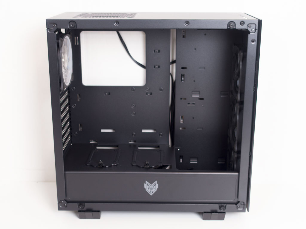
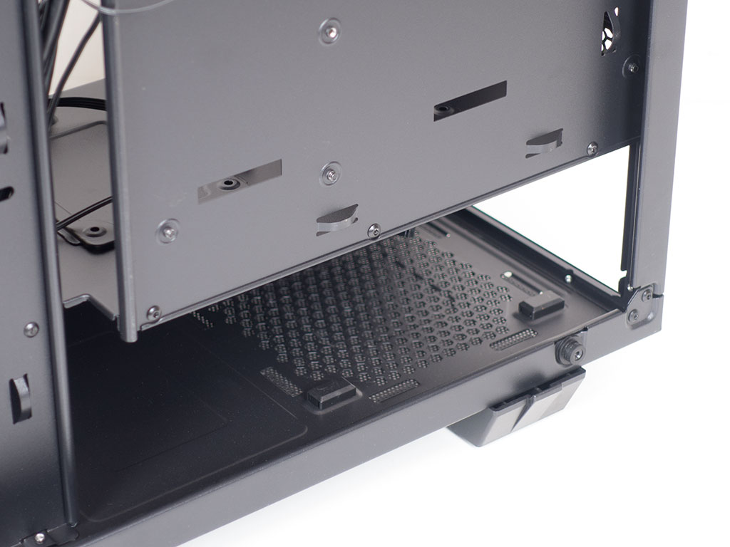
To gain access to the interior of the CMT510, simply remove the thumb screws and pull the panels away from the chassis. At first look, the minimalistic design approach continues on the inside, with the lack of any vertical drive bays. There are no openings for cable management in the motherboard tray. Instead, FSP has opted for a separate, offset plate to create a routing opening. If you look closely, there are two mounting possibilities for SDD trays underneath the CPU cooler's opening. As we will see later on, FSP includes two such bits on the shroud. This means you could move them here if you would rather like to hide them.
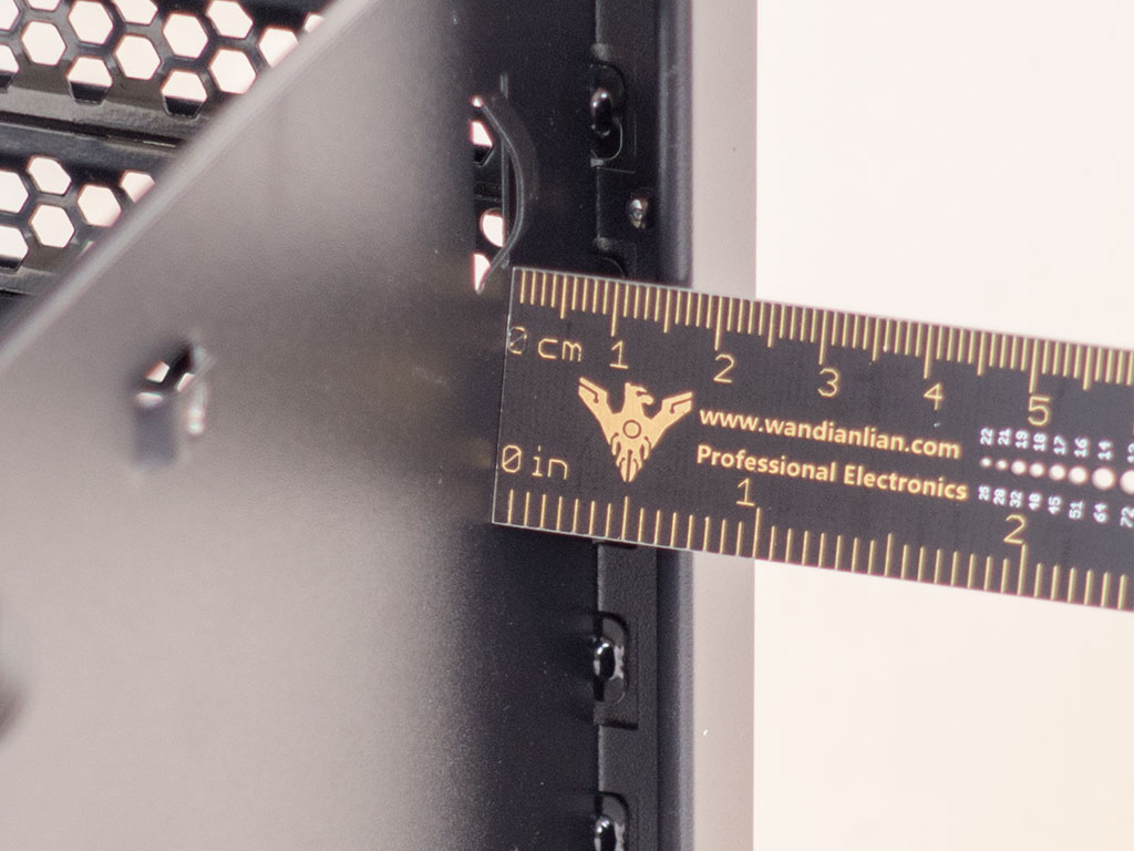
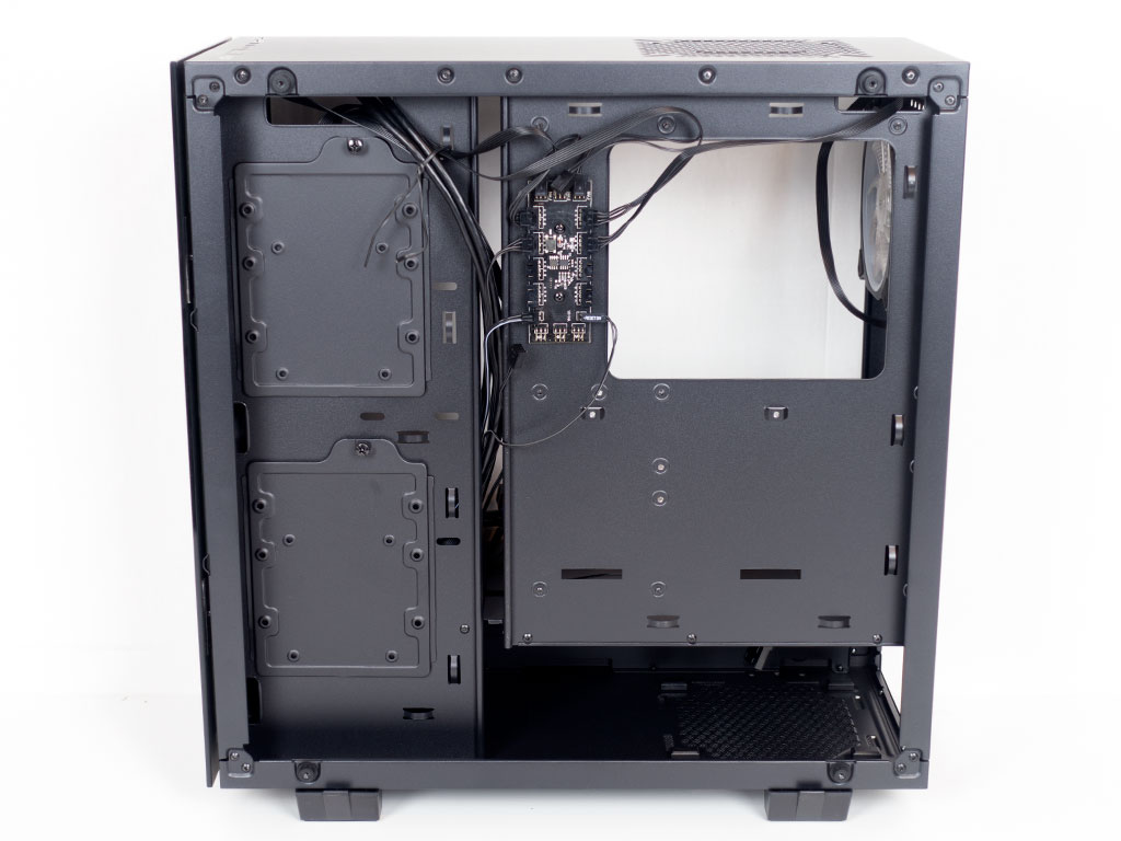
This separate plate has been moved into the chassis a bit more to accommodate 3.5" drives, of which you may install up to two within the CMT510. There is around 17 mm of space between the motherboard tray and glass side panel. While not as much as with other enclosures out there, it should be enough to route everything past this chokepoint.
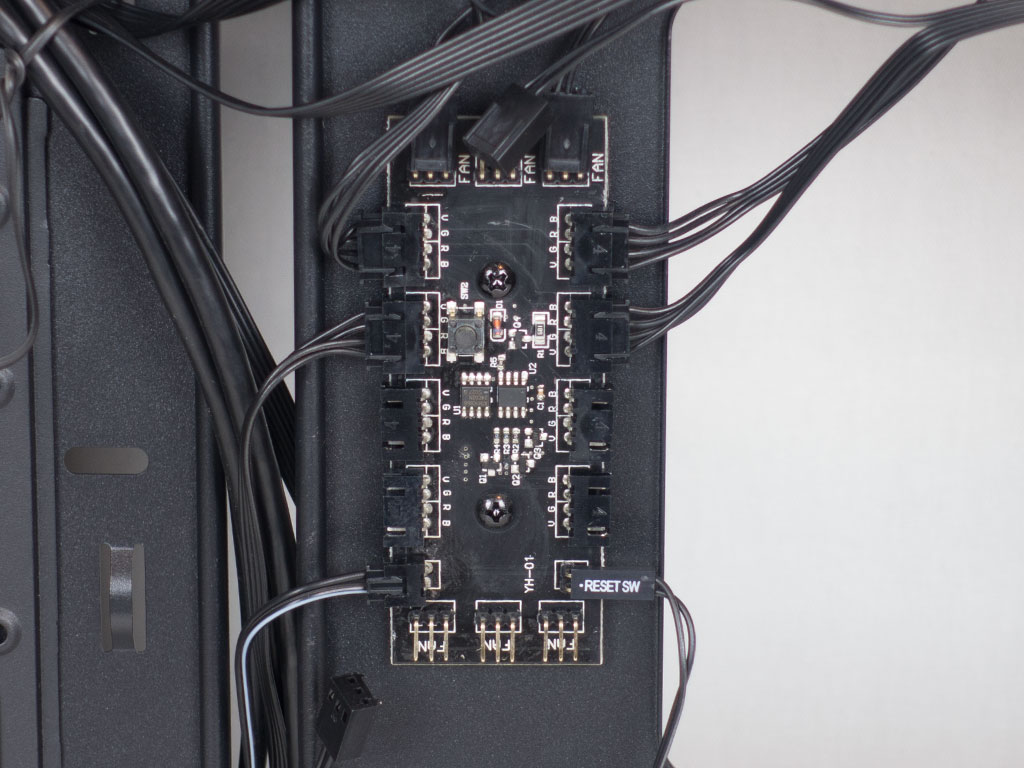
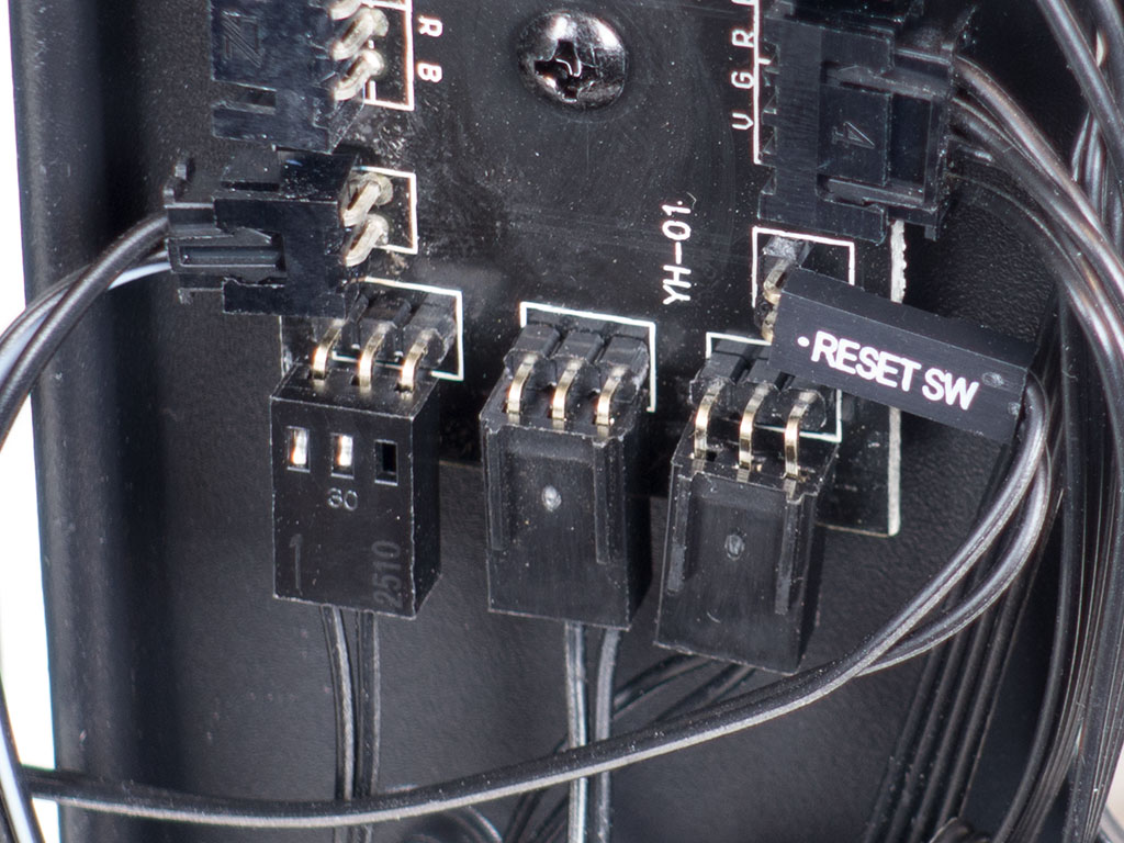
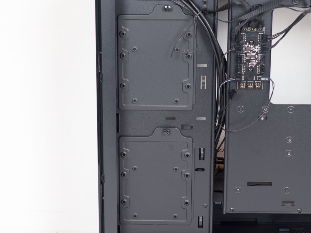
There is also a PCB capable of having up to six fans attached to it present. The RGB fans from FSP come with two headers: one 3-pin for the fan and a separate 4-pin for the LEDs. Unfortunately, the 3-pin headers are just bent pins and do not feature the usual plastic bit for such a connector, which means your fan plugs will end up sliding off the pins very easily.
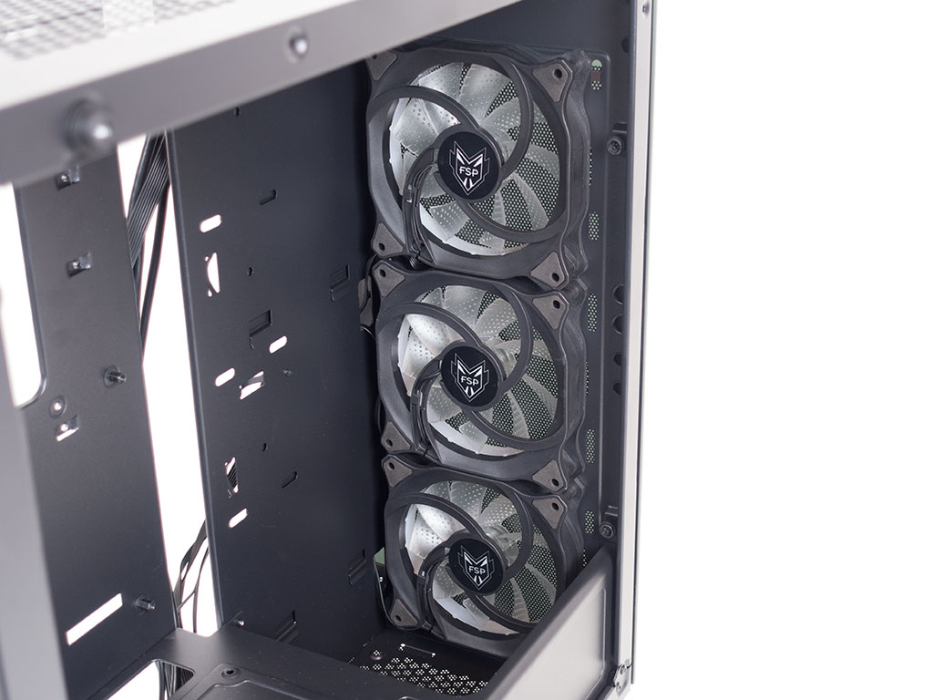
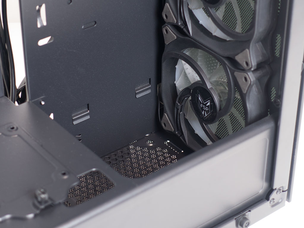
The three high-quality fans the chassis comes with out of the box in front take up all the fan-mounting possibilities there. You may install a thick radiator of up to 360 mm in size here without issue as well.
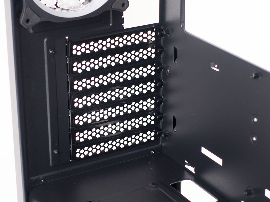
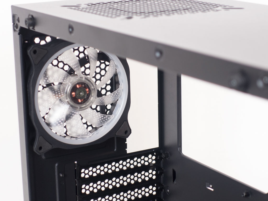
In the rear, the PSU bay underneath the metal shroud comes with four rubber bits as an anti-vibration measure. Above that, the expansion bays may be released from outside of the case, which makes the CMT510 a little bit more compact. In the very top, the fourth retail-grade fan can be found. It is identical to the ones in the front, which means your whole system will be lit evenly once turned on.
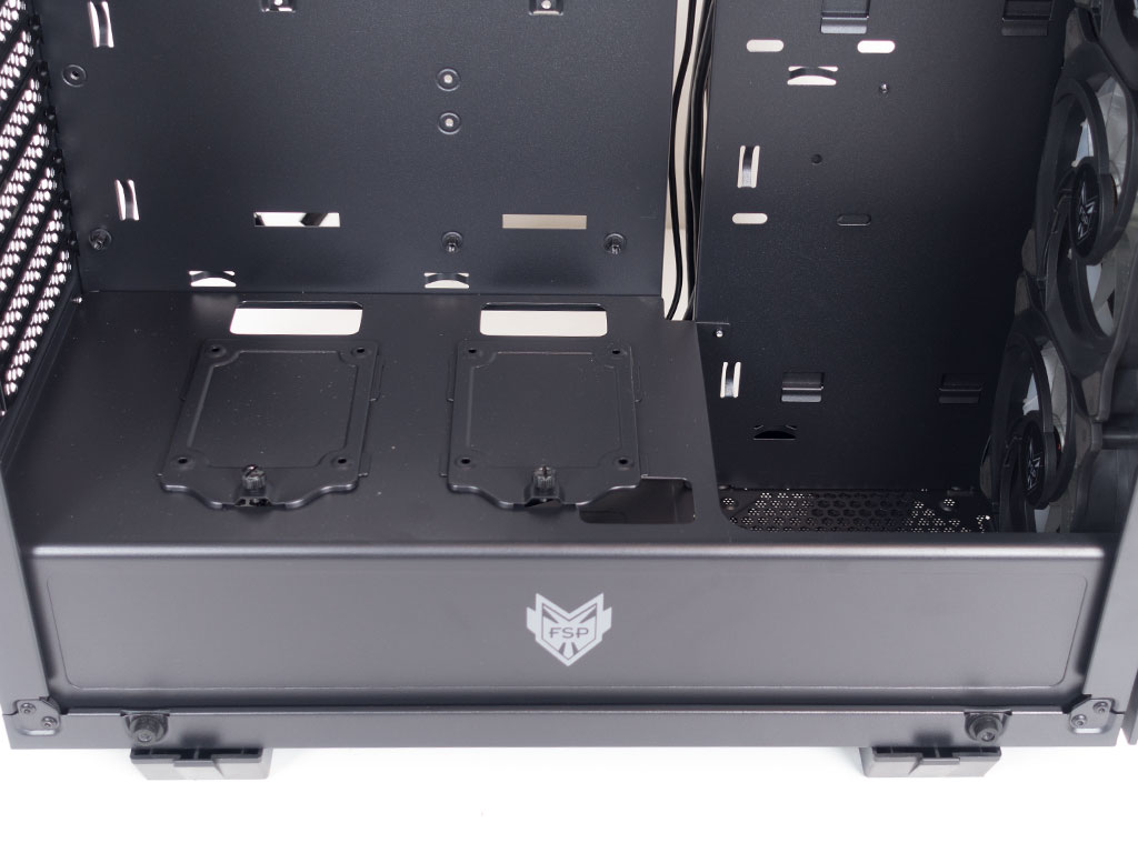
The aforementioned shroud is made out of metal as well, which means there is essentially no plastic anywhere to be found within the FSP CMT510. An FSP logo adds a little splash of branding here as there is no logo on any of the glass panels.
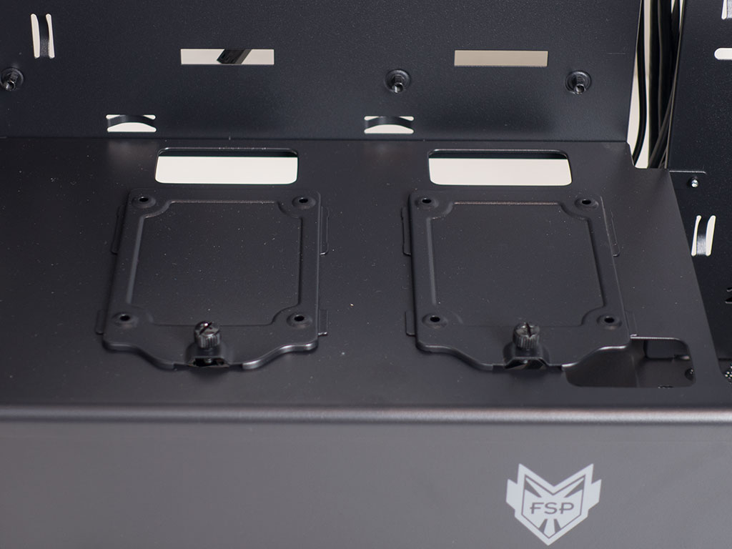
As stated previously, there is a large gap in the shroud, which means you shouldn't run into issues with adding potent liquid-cooling setups all across the front of the chassis. The two SSD trays are held in place by thumb screws and may easily be removed for a quick and painless assembly.
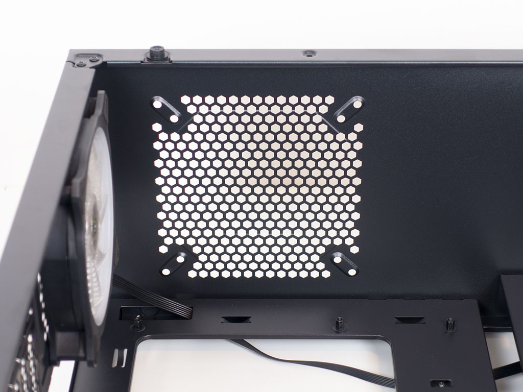
You will find a single 120/140 mm fan opening in the ceiling. While some may criticize the lack of more for large liquid cooling in this area of the chassis, the reality is that most users won't be utilizing such a possibility anyways. However, viewing the opening from this direction unfortunately confirms that there is no dust filter to keep grime from getting into the chassis through this opening over time.
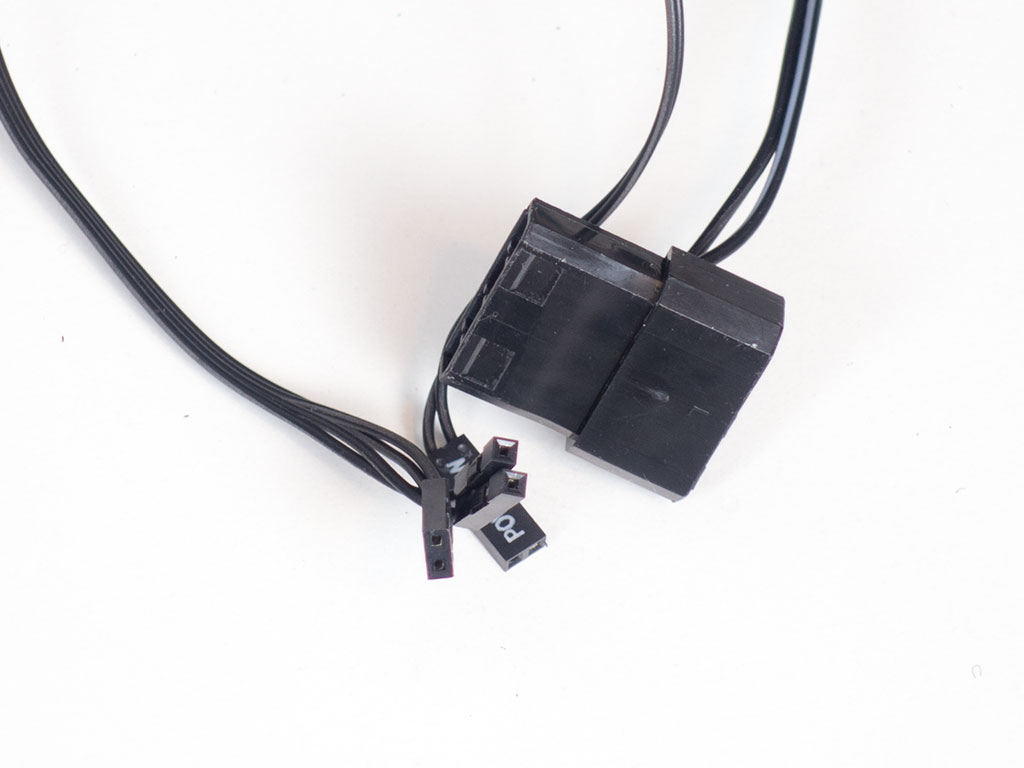
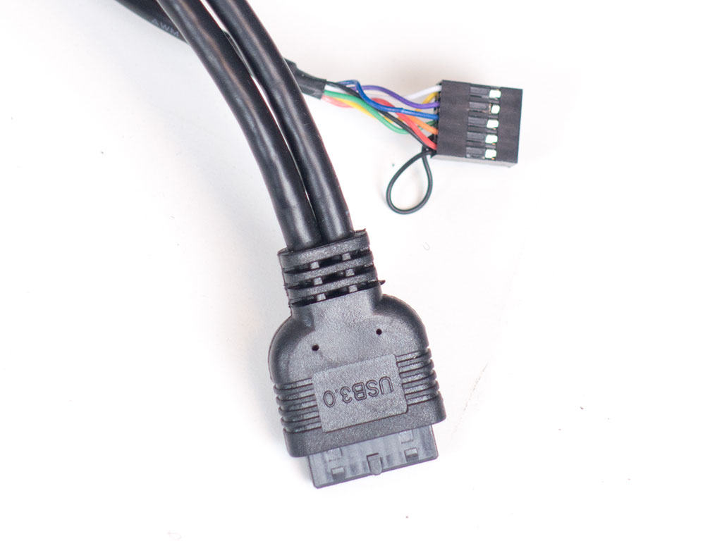
All the cables within the CMT510 are of the standard variety. The PCB is powered by a pass-through Molex connector. An interesting tidbit is the fact that FSP has re-purposed the reset lead as an LED color toggle. This means you can still use the button on top of the case as a reset button.
Jul 10th, 2025 02:38 CDT
change timezone
Latest GPU Drivers
New Forum Posts
- Do you still use Antivirus software on your latest hardware? (75)
- Screen burn-in (21)
- TPU's Nostalgic Hardware Club (20493)
- 3DMARK "LEGENDARY" (326)
- Post Your TIMESPY, PCMARK10 & FIRESTRIKE SCORES! (2019) (321)
- 5070ti overclock...what are your settings? (47)
- 'NVIDIA App' not usable offline? (1)
- G-Sync Not Working in Borderless / Window Mode - Windows 11 (5)
- [GPU-Z Test Build] New Kernel Driver, Everyone: Please Test (78)
- Friend's monitor randomly loses signal (3)
Popular Reviews
- NZXT N9 X870E Review
- NVIDIA GeForce RTX 5050 8 GB Review
- Fractal Design Epoch RGB TG Review
- Corsair FRAME 5000D RS Review
- Fractal Design Scape Review - Debut Done Right
- AMD Ryzen 7 9800X3D Review - The Best Gaming Processor
- Sapphire Radeon RX 9060 XT Pulse OC 16 GB Review - An Excellent Choice
- Upcoming Hardware Launches 2025 (Updated May 2025)
- Sapphire Radeon RX 9070 XT Nitro+ Review - Beating NVIDIA
- PowerColor ALPHYN AM10 Review
TPU on YouTube
Controversial News Posts
- Intel's Core Ultra 7 265K and 265KF CPUs Dip Below $250 (288)
- Some Intel Nova Lake CPUs Rumored to Challenge AMD's 3D V-Cache in Desktop Gaming (140)
- NVIDIA Launches GeForce RTX 5050 for Desktops and Laptops, Starts at $249 (117)
- AMD Radeon RX 9070 XT Gains 9% Performance at 1440p with Latest Driver, Beats RTX 5070 Ti (116)
- NVIDIA GeForce RTX 5080 SUPER Could Feature 24 GB Memory, Increased Power Limits (115)
- Microsoft Partners with AMD for Next-gen Xbox Hardware (105)
- Intel "Nova Lake‑S" Series: Seven SKUs, Up to 52 Cores and 150 W TDP (100)
- NVIDIA DLSS Transformer Cuts VRAM Usage by 20% (97)