 3
3
FSP Hydro X Series 550 W Review
Load Regulation, Hold-up Time & Inrush Current »A Look Inside & Component Analysis
Before reading this page, we strongly suggest a look at this article, which will help you understand the internal components of a PSU much better. Our main tool for the disassembly of the PSU is a Thermaltronics TMT-9000S soldering and rework station. It is of extreme quality and is equipped with a matching de-soldering gun. With such equipment in hand, breaking apart every PSU is like a walk in the park!| FSP HGX550 Parts Description | |
|---|---|
| Primary Side | |
| Transient Filter | 4x Y caps, 1x X caps, 2x CM chokes, 1x MOV |
| Bridge Rectifier(s) | 1x GBJ1506 (600V, 15A @ 100°C) |
| Inrush Current Protection | NTC Thermistor & Relay |
| APFC Mosfets | 2x STMicroelectronics STF18N60M2 (650V, 8A @ 100°C, 0.28Ω) |
| APFC Boost Diode | 1x STMicroelectronics STTH8R06FP (600V, 8A @ 100°C) |
| Hold-up Cap(s) | 1x Nippon Chemi-Con (450V, 390uF, 105°C, KMR series, 2000h @ 105°C) |
| Main Switchers | 2x Toshiba TK12A60W (600V, 11.5A @ 150°C, 0.265Ω @ 25°C) |
| APFC Controller | Infineon ICE2PCS02 Supporting IC: Fairchild KA393A APFC Disconnect: SEN013DG |
| Switching Controller | Champion CM6901T2X |
| Topology | Primary side: Half-Bridge & LLC Resonant Converter Secondary side: Synchronous Rectification & DC-DC converters |
| Secondary Side | |
| +12V | 2x Toshiba TPHR8504PL (U-MOSIX-H Series, 40V, 150A @ 25°C, 0.85 mohm @ VGS = 10 V) |
| 5V & 3.3V | DC-DC Converters: 6x International Rectifier IRLR8726PbF FETs (30V, 61A @ 100 °C, 5.8 mohm) PWM Controllers: 1x ANPEC APW7159C |
| Filtering Capacitors | Electrolytics: Nippon Chemi-Con (105 °C, KY, KZE), Rubycon (105 °C, 6000~10000 hours, ZLH) Polymers: Teapo (Taiwan), CapXon (Taiwan) |
| Supervisor IC | PS223 (OVP, UVP, OCP, SCP, OTP ) |
| Fan Model | Power Logic PLA12025B12M (12V, 0.20A, 65.15 CFM, 33.3 dB[A], 1800 RPM, Double Ball-Bearing) |
| 5VSB Circuit | |
| Rectifying Diode | International Rectifier IRFR1018E |
| Standby PWM Controller | Power Integrations SC1225K |
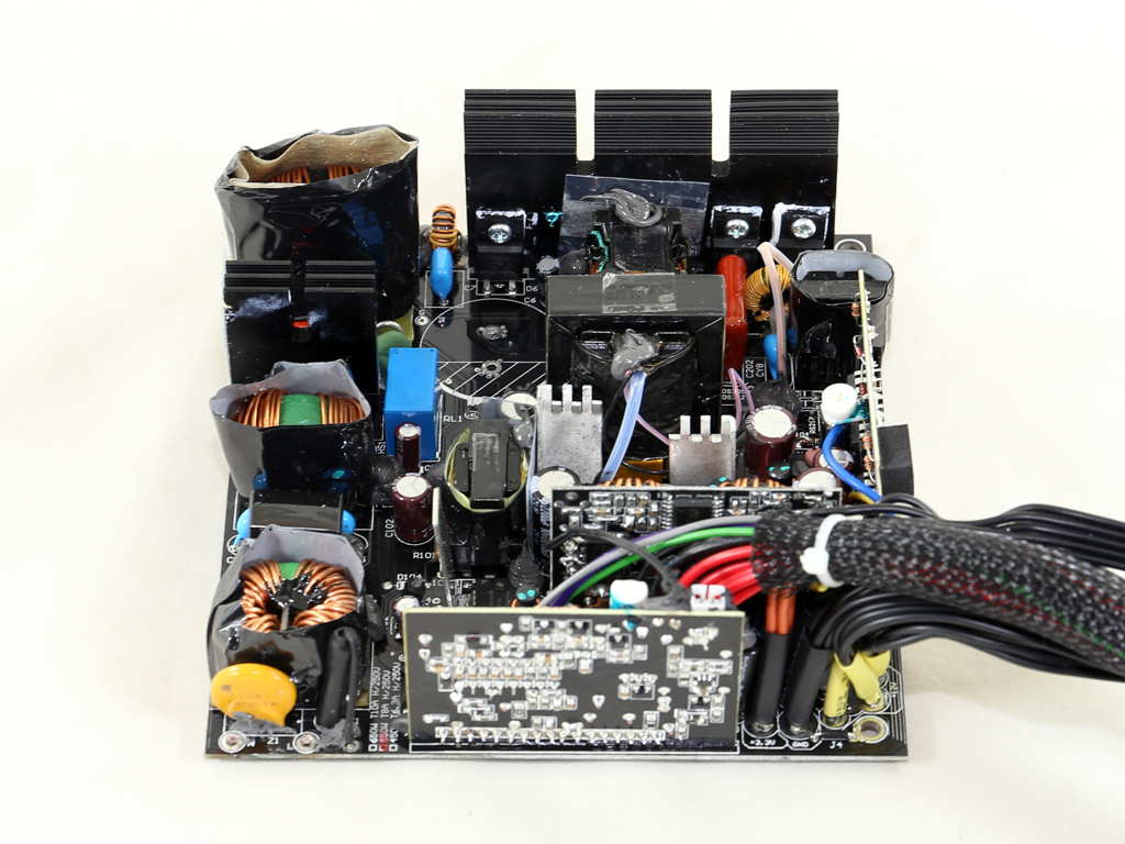
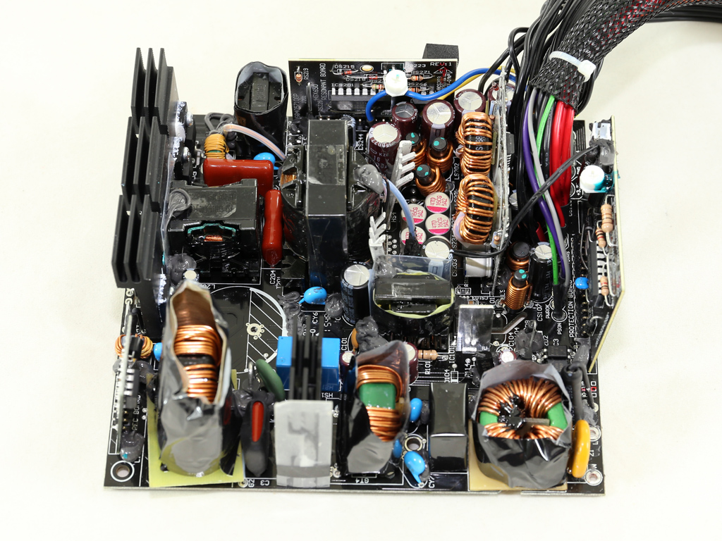
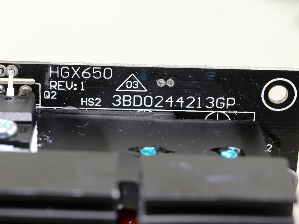
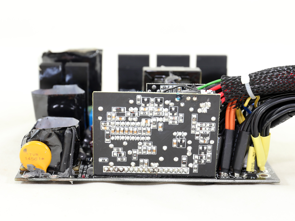
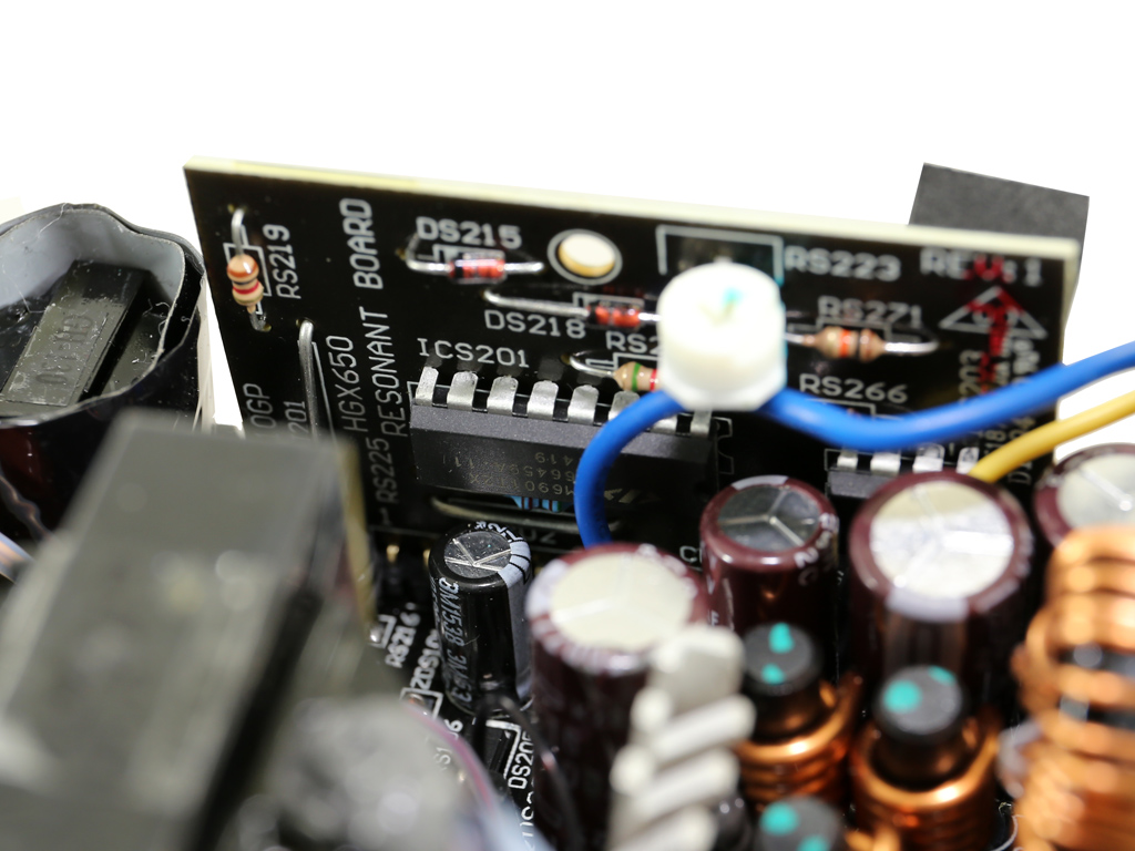
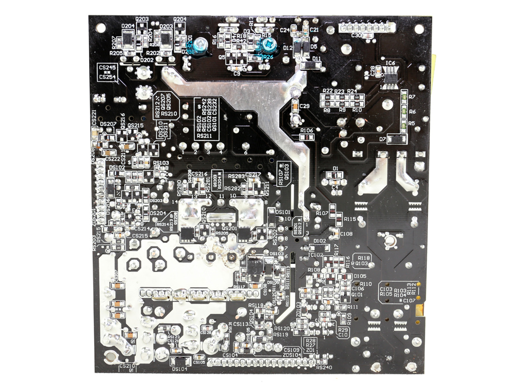
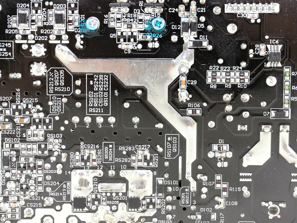
The PCB is pretty small and isn't choke-full of components since the PSU's capacity is low. The primary heatsink is large enough, but there are only two small heasinks in the secondary side. While the enclosure will help, these heatsinks are supposed to handle the heat the +12V FETs produce. The primary switchers are arranged into a half-bridge topology, and an LLC resonant converter is used to boost efficiency. A synchronous design is used in the secondary side, with two DC-DC converters that generate the minor rails. All electrolytic caps are by Japanese manufacturers, and we also spotted several polymer caps by Teapo and CapXon.
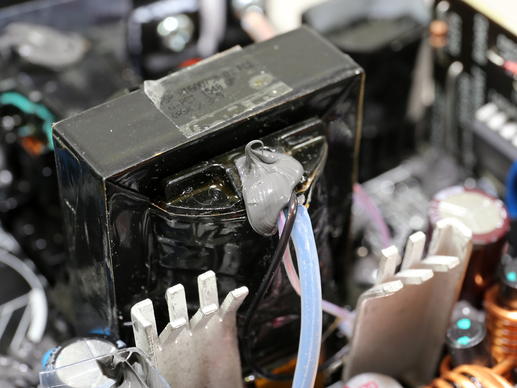
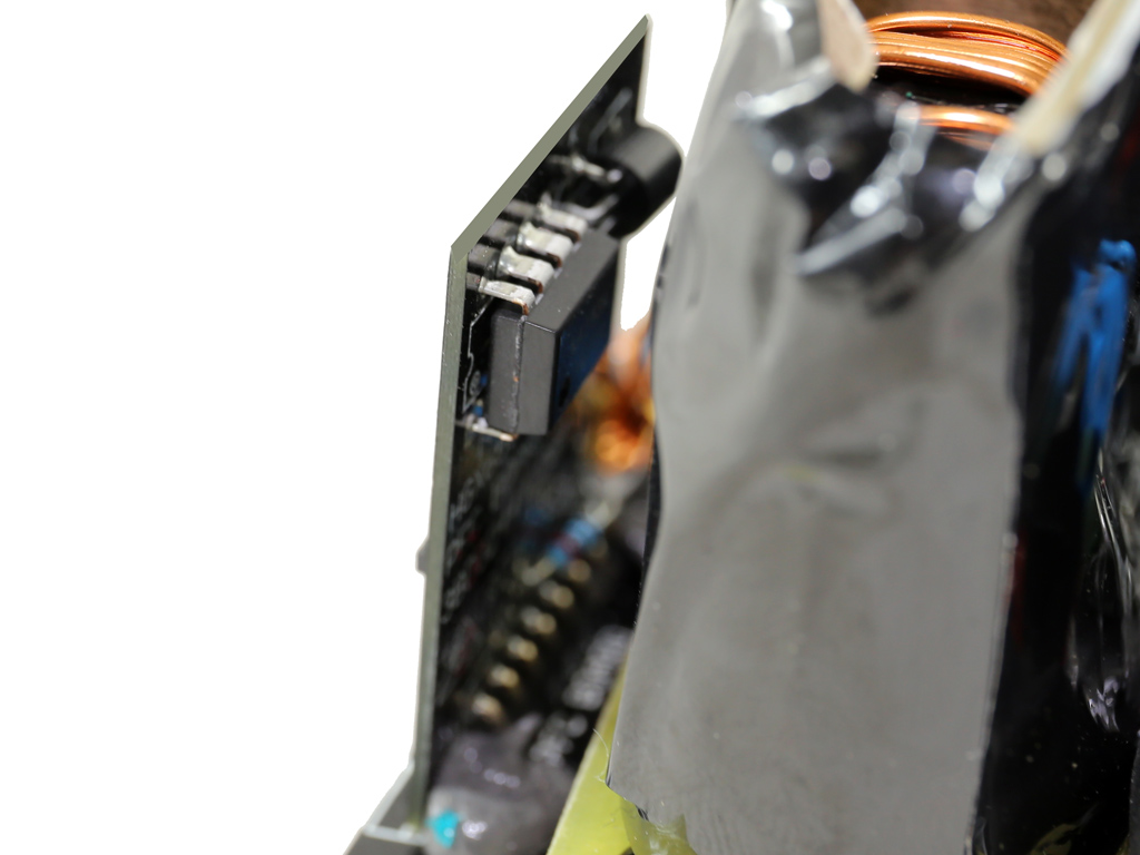
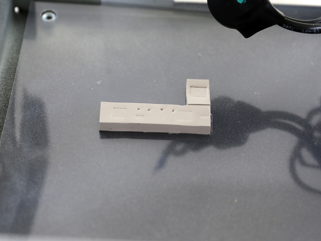
The only thing that doesn't look nice internally is this cable for the fan-control thermistor. A little longer and it could be routed properly. The thermistor is attached to the main transformer and doesn't provide accurate information to the fan-control circuit despite FSP's claims that it does, which has the fan spin at roughly the same speed regardless of whether the PSU is running hot or not. To make matters worse, the lowest fan-speed setting is way too high for a Gold-certified mid-capacity PSU. FSP should look into optimizing this PSU's fan profile as soon as possible.
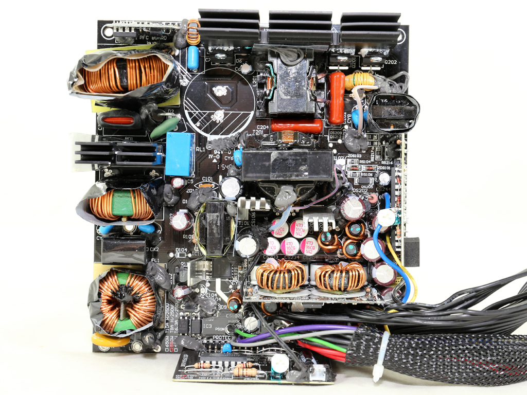
The AC receptacle only holds two Y caps. The rest of the EMI filter is on the main PCB and consists of an X and two Y caps, two CM chokes, and a pretty large MOV. We would like to see another X cap included.

An NTC thermistor protects the unit against large inrush currents, and it is supported by a bypass relay, which allows for it to cool down faster.
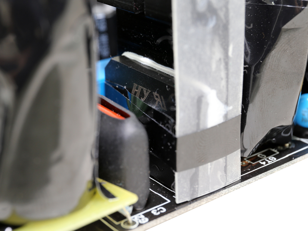
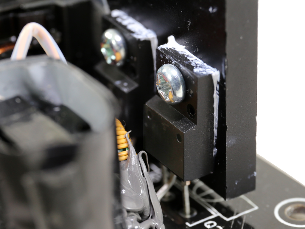
The single bridge rectifier is a GBJ1506, bolted to a dedicated heatsink. The rectifier is wrapped in duct tape for reasons we aren't privy to.
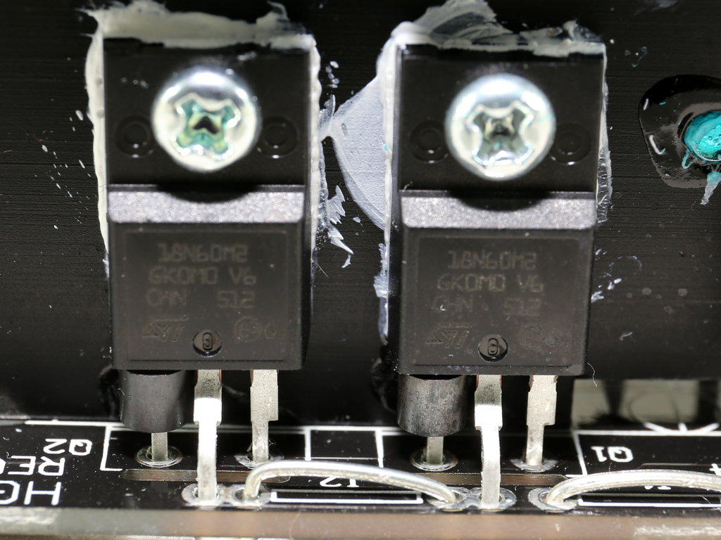
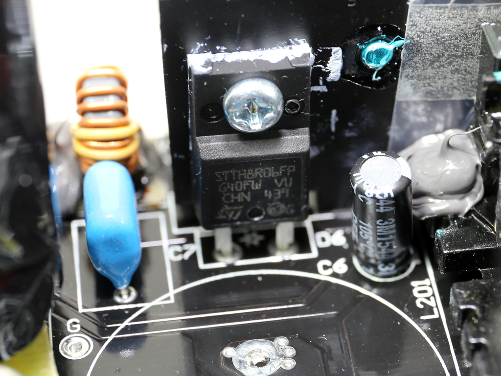
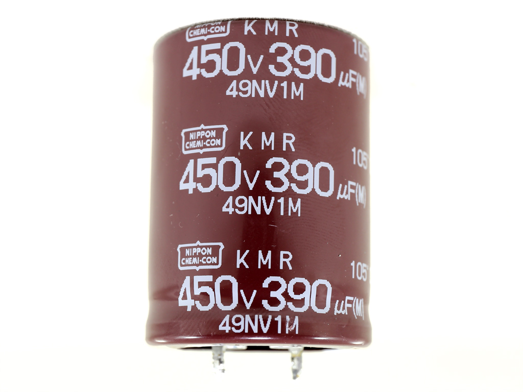
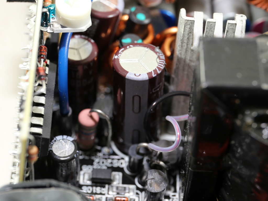
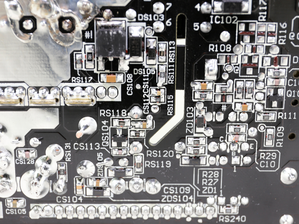
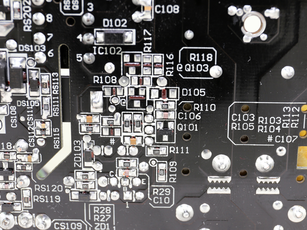
The APFC converter uses two STMicroelectronics STF18N60M2 FETs and a STTH8R06FP boost diode, both of which are by the same manufacturer. The bulk cap is a Chemi-Con KMR (450 V, 390 uF, 105 °C, 2000h @ 105 °C), a bulk cap with a pretty high voltage rating. Most manufacturers use 420 V or 400 V caps here, while the APFC's bus voltage is around 380 VDC.
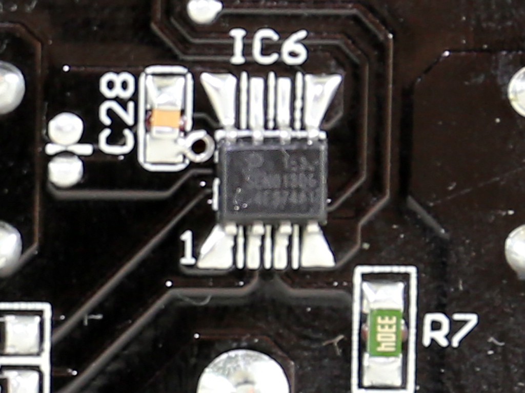
Right under the APFC's coil and on the solder side of the mainboard is a SEN013DG IC that disconnects the APFC converter while the PSU is in standby mode, which reduces energy consumption. This little trick will also increase the 5VSB rail's efficiency.
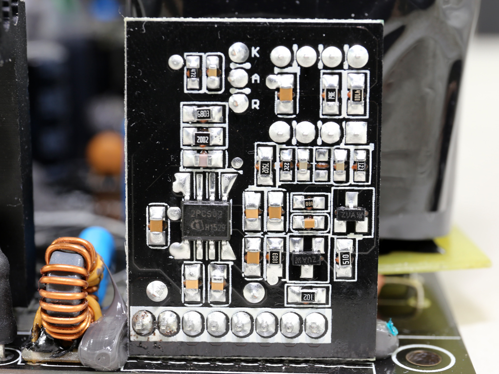
The APFC controller is on a small PCB. It is an Infineon ICE2PCS02 and is supported by a Fairchild KA393A operation amplifier (op-amp).
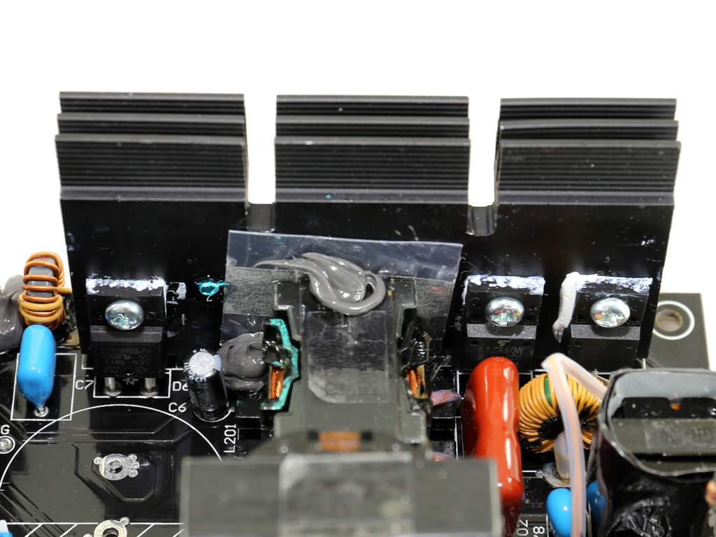
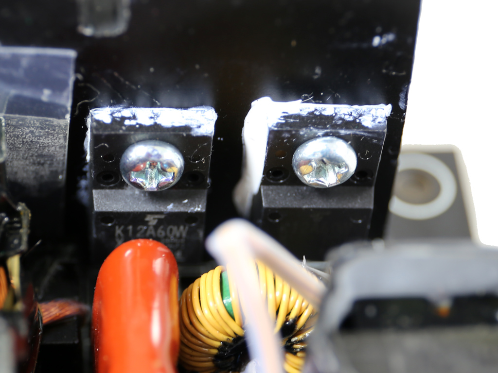
The main switchers are a pair of Toshiba TK12A60W FETs FSP arranged into a half-bridge topology. An LLC resonant converter is also utilized to increase efficiency.
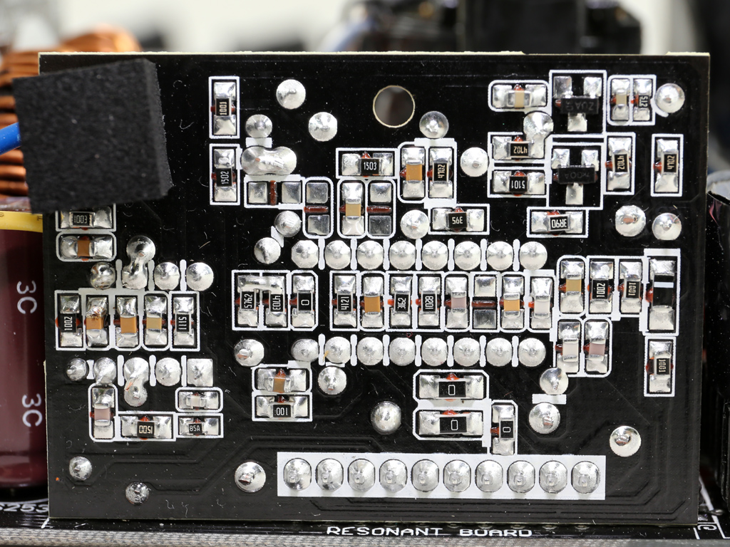
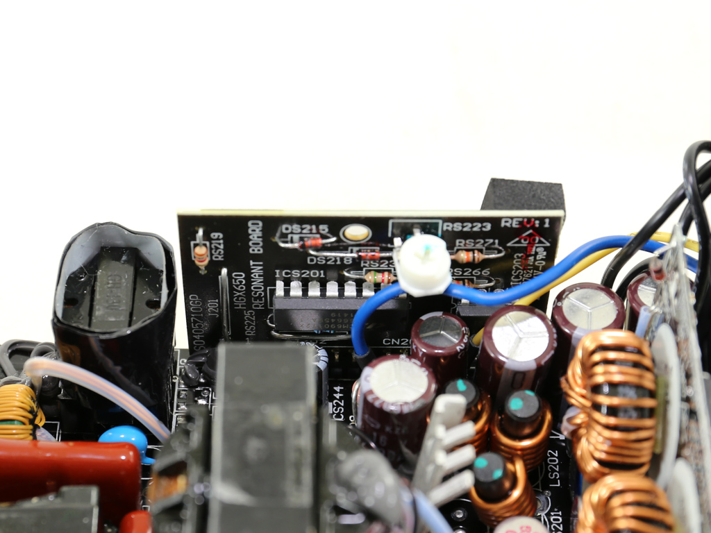
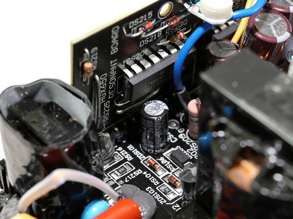
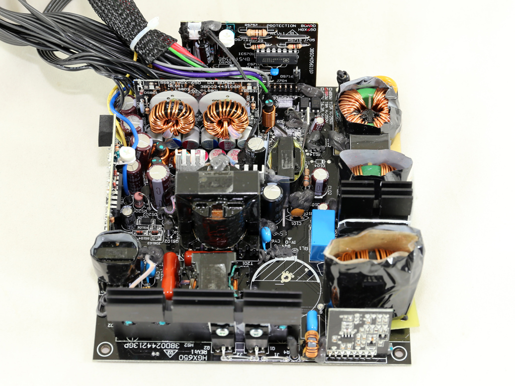
A vertical PCB holds the LLC resonant converter, a Champion CM6901T2X, the LLC resonant converter for Gold- and Platinum-certified PSUs. There is also an op-amp on the board, well hidden behind the filtering caps of the secondary side.
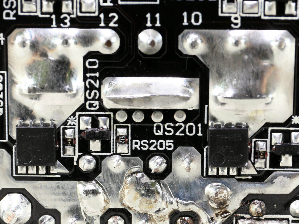
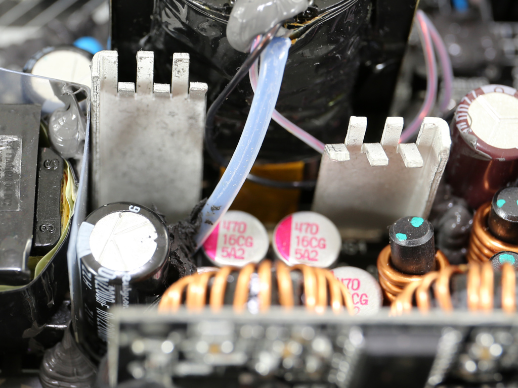
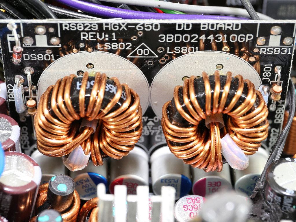
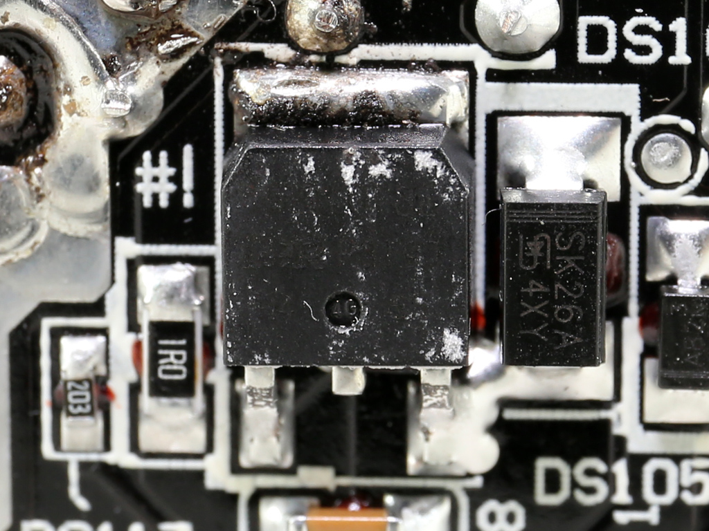
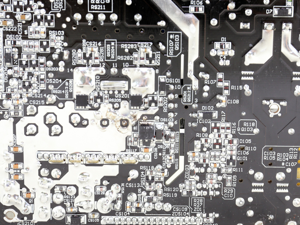
The FETs that regulate the +12V rail on the secondary side are two Toshiba TPHR8504PLs. These don't look like regular FETs because they have eight instead of three pins; four of these pins are used by the drain and three by the source, and the last one is the gate. Heat dissipation on the main board's primary side is handled by two small heatsinks right above the +12V FETs and the PSU's chassis.
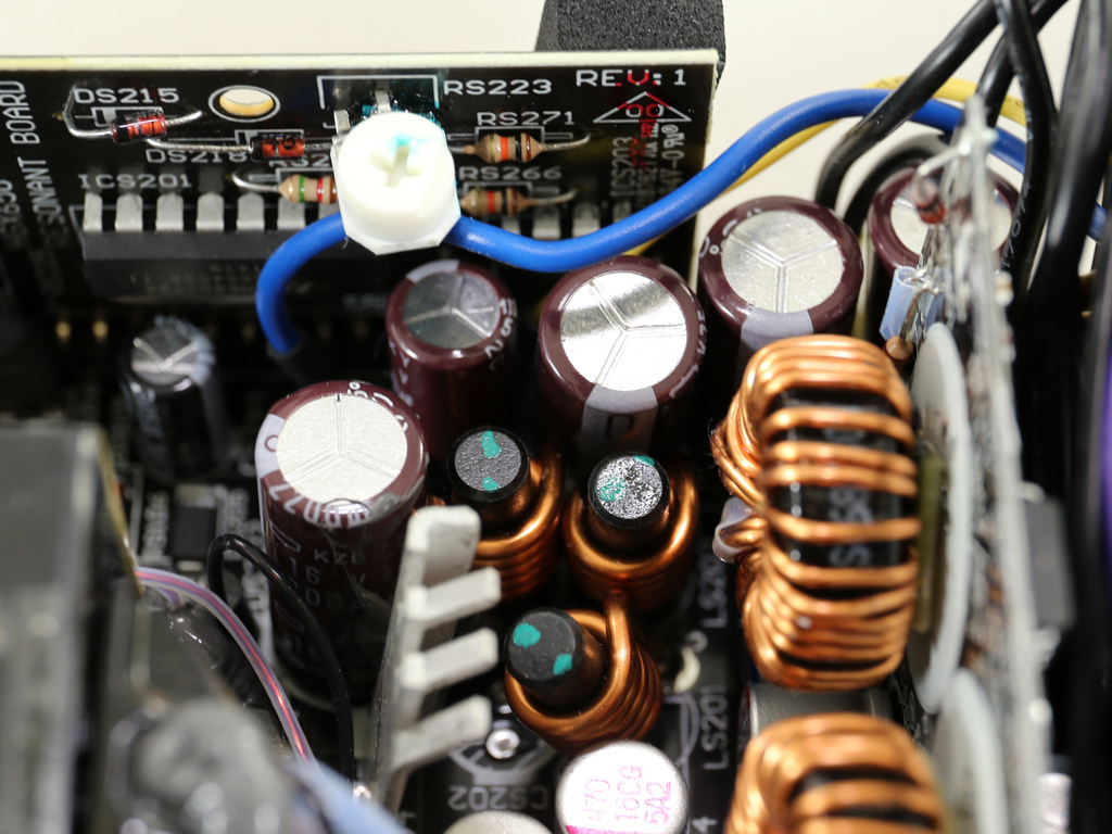
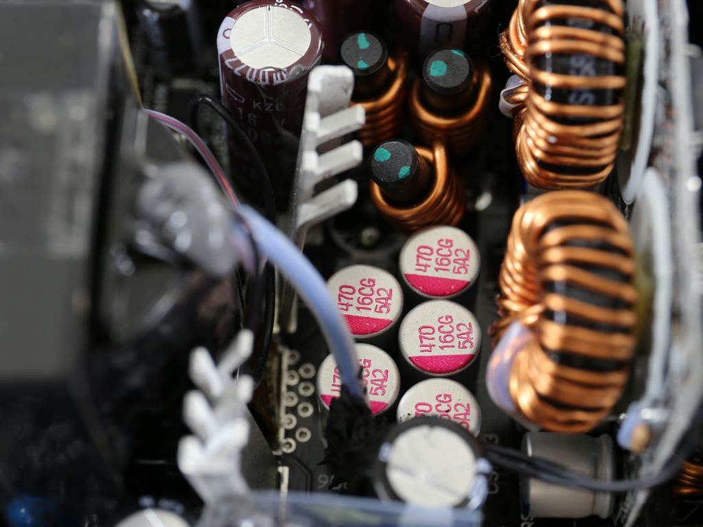
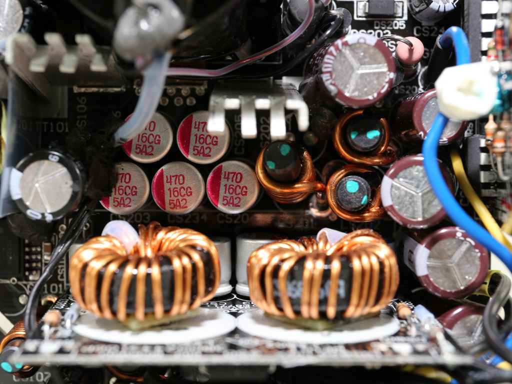
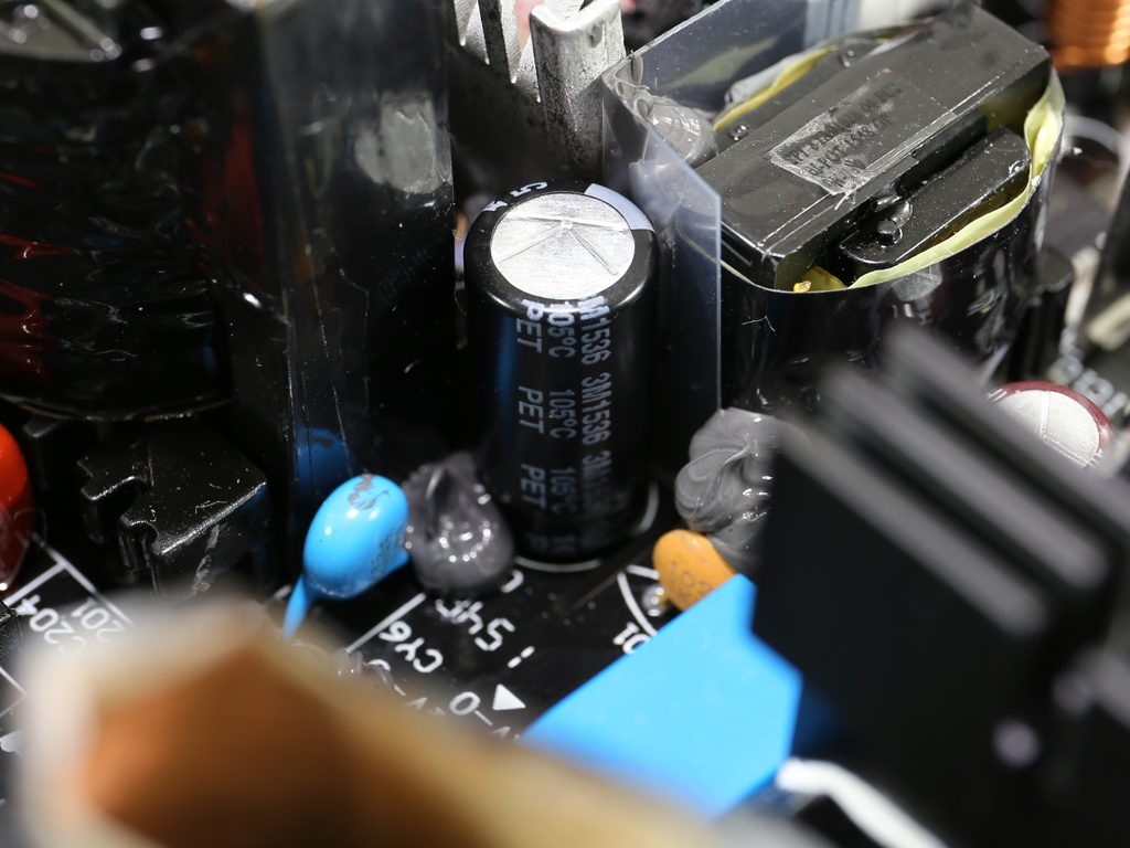
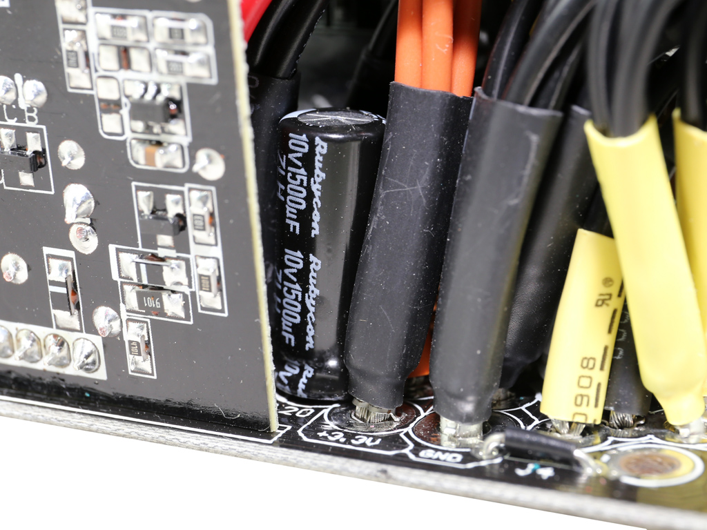
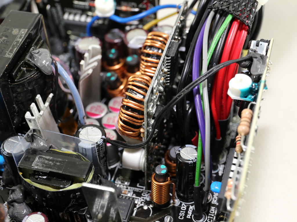
There are several filtering Chemi-Con electrolytic caps (105 °C, KY, KZE) on the secondary side, and we also found a number of high quality Rubycon caps (105 °C, 6000~10000 hours, ZLH). Some polymer caps by Teapo are also used to filter the +12V rail.
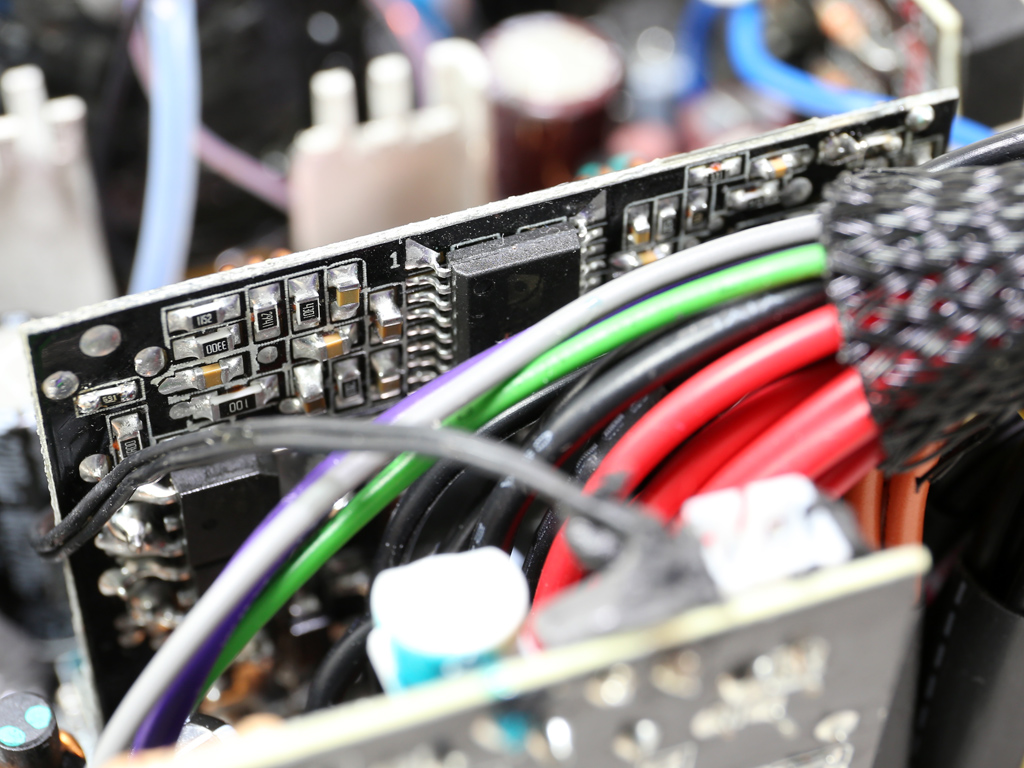
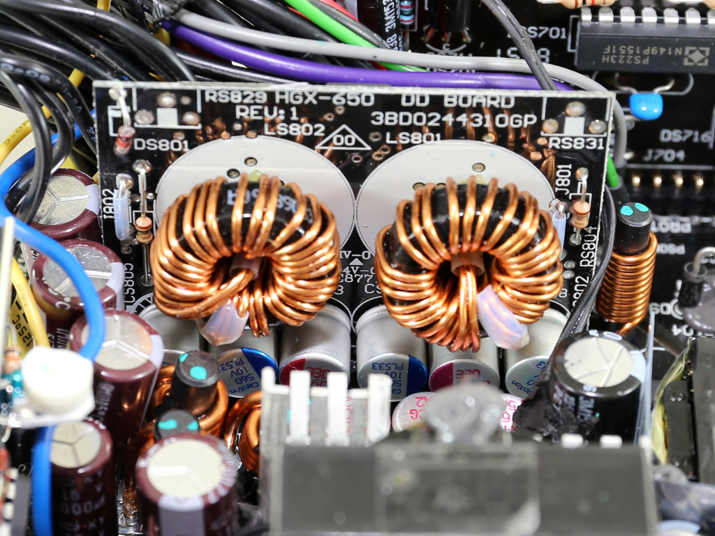
Two DC-DC converters generate the minor rails. Each of these uses three International Rectifier IRLR8726PbF FETs, and their common PWM controller is an ANPEC APW7159C IC. A mix of Teapo and CapXon polymer caps filter the minor rails. Some of you probably won't like the use of CapXon caps, but these won't pose a problem as the unit ages because they don't contain any liquid electrolyte.
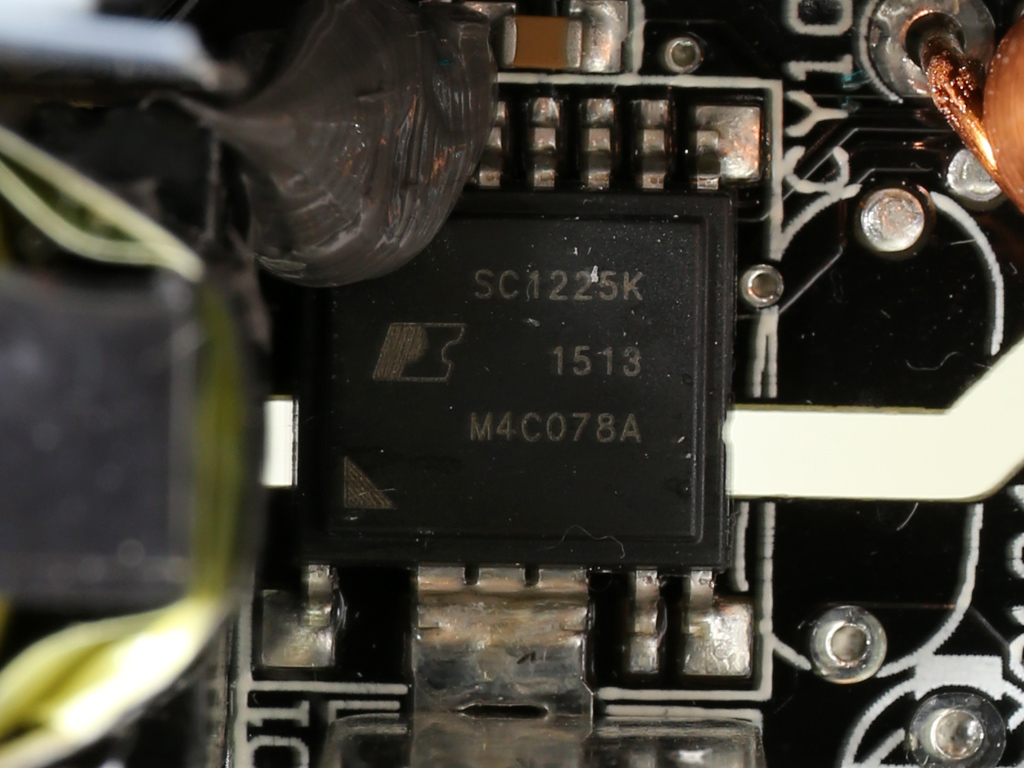
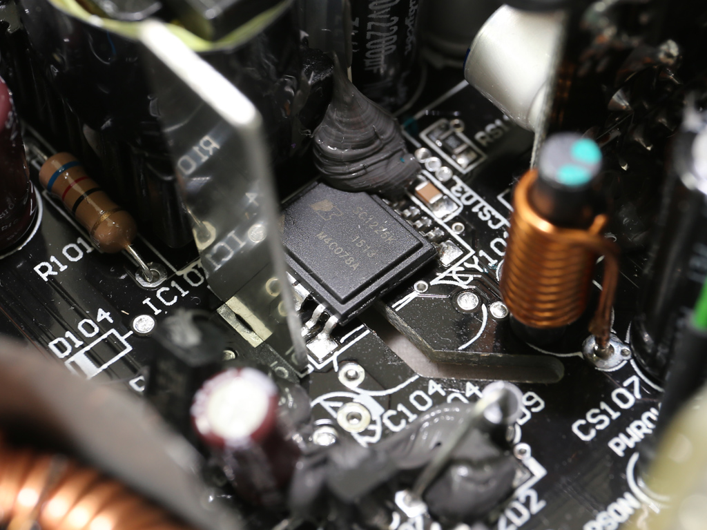
The standby PWM controller is a Power Integrations SC1225K, while the FET that regulates the 5VSB rail is an IRFR1018E by International Rectifier. This FET is installed on the PCB's solder side.
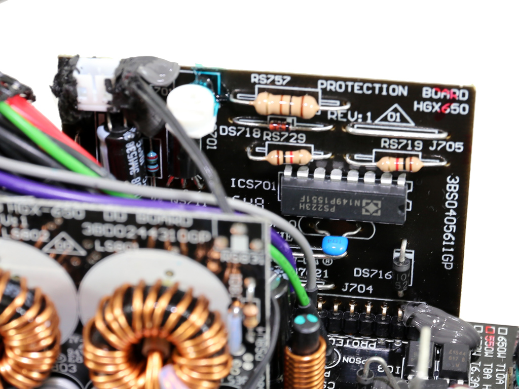
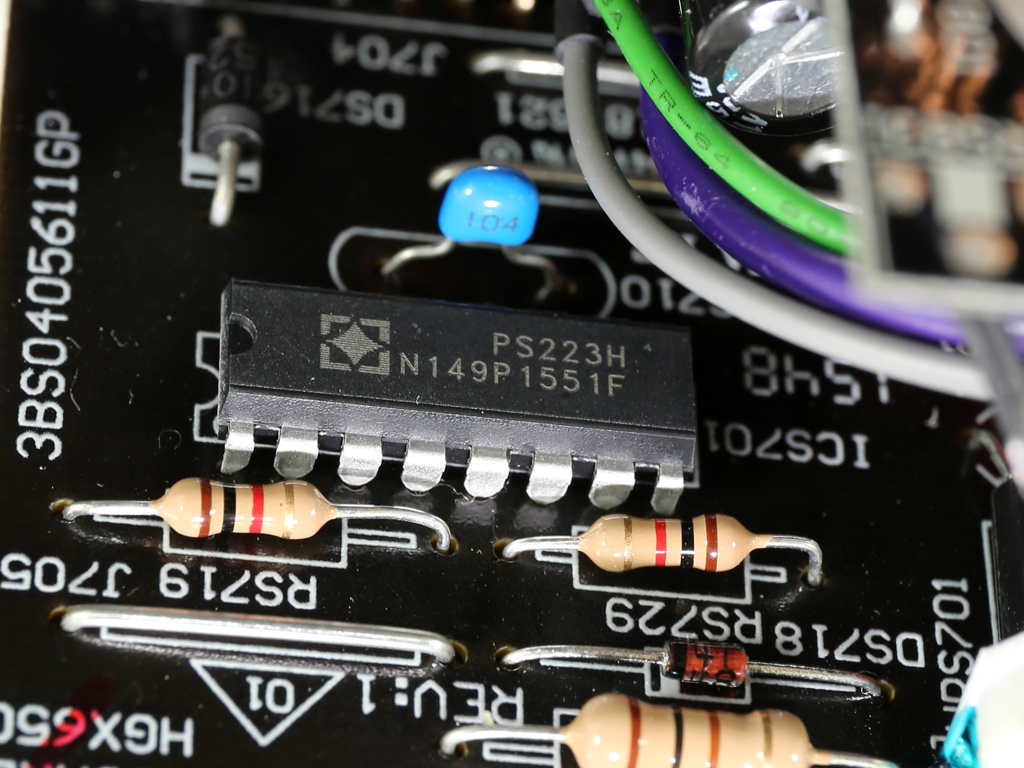
The protections IC is a SITI PS223, one of the very few supervisor ICs with Over Temperature Protection (OTP) out of the box. The same IC also supports OCP for two +12V channels, but this PSU only has one.
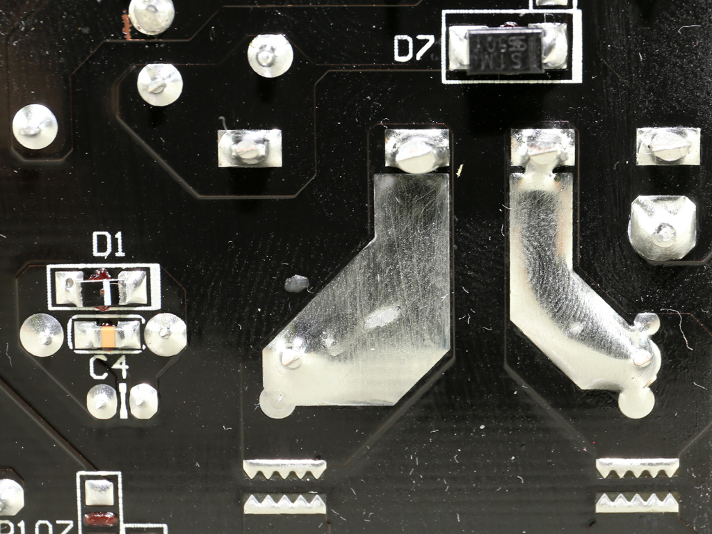
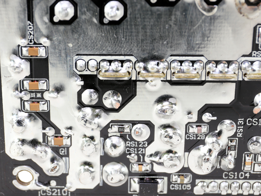
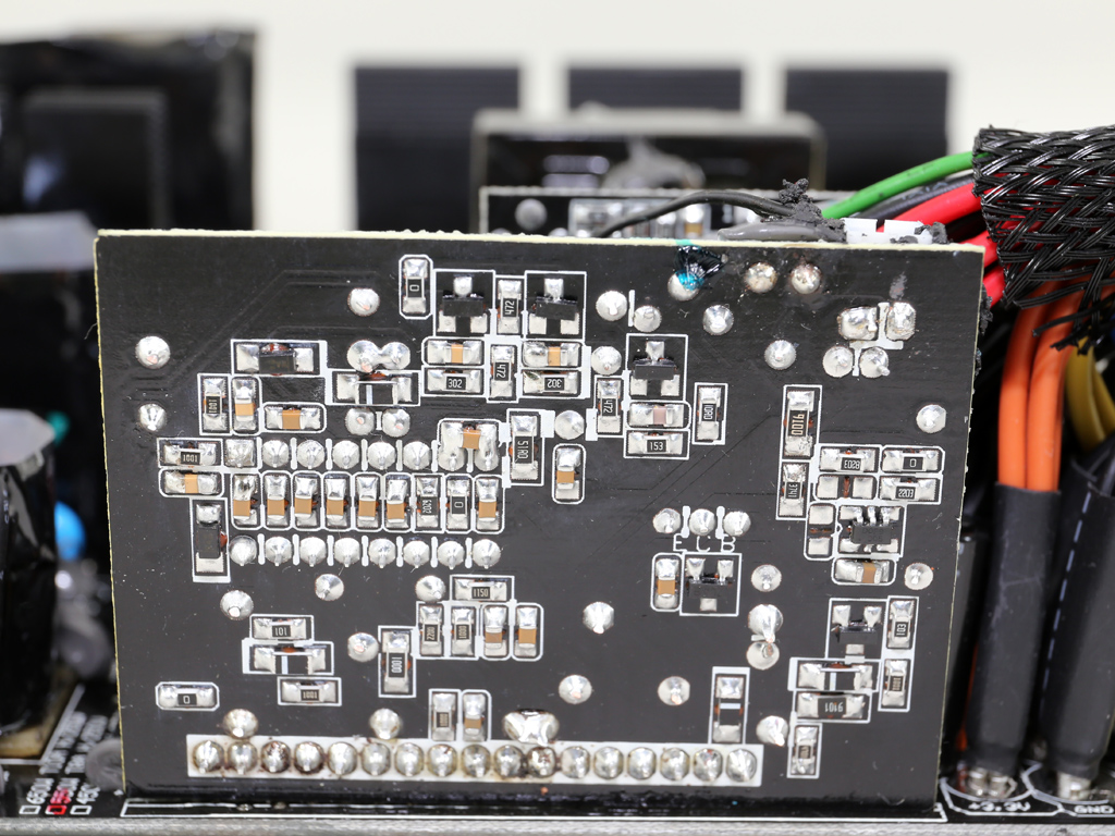
Soldering quality is quite good overall, and we didn't spot any long component leads that could cause problems.
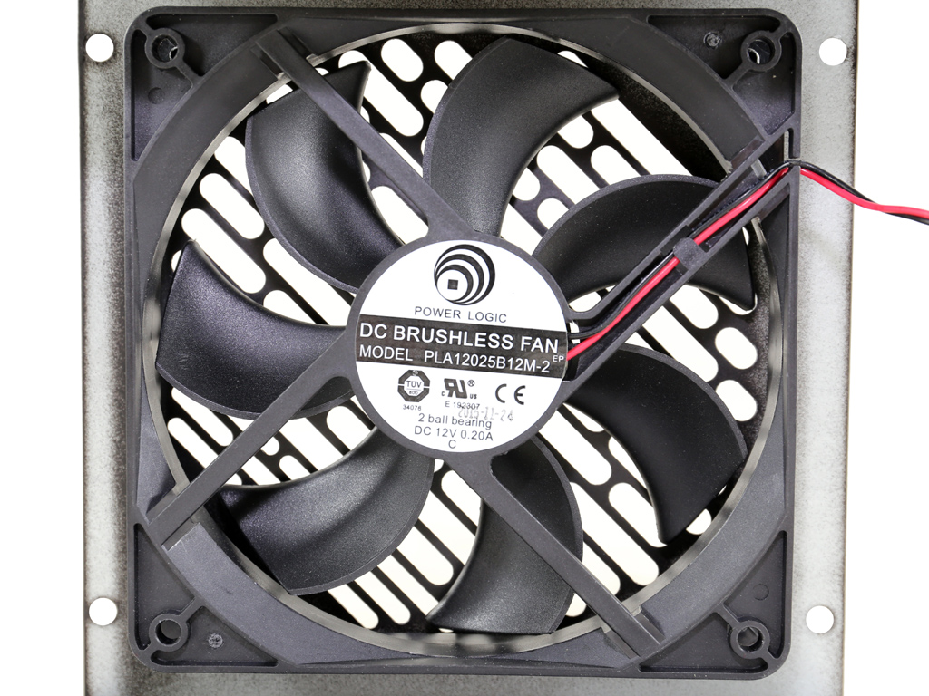
The fan is by Power Logic, and its model number is PLA12025B12M (12V, 0.20A, 65.15 CFM, 33.3 dB[A], 1800 RPM, Double Ball-Bearing). It uses double ball-bearings, which will have it last longer. The only downside looks to be the fan profile that is almost nonexistent since the fan operates at around 1200 RPM most of the time.
Jul 5th, 2025 16:17 CDT
change timezone
Latest GPU Drivers
New Forum Posts
- Do you use Linux? (677)
- Optane performance on AMD vs Intel (58)
- Frametime spikes and stuttering after switching to AMD CPU? (521)
- Stalker 2 is looking great. (187)
- b550m aorus elite not posting with new ram (7)
- Gigabyte graphic cards - TIM gel SLIPPAGE problem (131)
- Can you guess Which game it is? (203)
- How do you view TPU & the internet in general? (With poll) (74)
- EVGA XC GTX 1660 Ti 8GB ROM (9)
- What are you playing? (23892)
Popular Reviews
- NVIDIA GeForce RTX 5050 8 GB Review
- Fractal Design Scape Review - Debut Done Right
- Crucial T710 2 TB Review - Record-Breaking Gen 5
- ASUS ROG Crosshair X870E Extreme Review
- PowerColor ALPHYN AM10 Review
- Sapphire Radeon RX 9060 XT Pulse OC 16 GB Review - An Excellent Choice
- Upcoming Hardware Launches 2025 (Updated May 2025)
- AMD Ryzen 7 9800X3D Review - The Best Gaming Processor
- Sapphire Radeon RX 9070 XT Nitro+ Review - Beating NVIDIA
- NVIDIA GeForce RTX 5060 8 GB Review
TPU on YouTube
Controversial News Posts
- Intel's Core Ultra 7 265K and 265KF CPUs Dip Below $250 (288)
- NVIDIA Grabs Market Share, AMD Loses Ground, and Intel Disappears in Latest dGPU Update (212)
- Some Intel Nova Lake CPUs Rumored to Challenge AMD's 3D V-Cache in Desktop Gaming (140)
- NVIDIA GeForce RTX 5080 SUPER Could Feature 24 GB Memory, Increased Power Limits (115)
- Microsoft Partners with AMD for Next-gen Xbox Hardware (105)
- NVIDIA Launches GeForce RTX 5050 for Desktops and Laptops, Starts at $249 (105)
- AMD Radeon RX 9070 XT Gains 9% Performance at 1440p with Latest Driver, Beats RTX 5070 Ti (102)
- Intel "Nova Lake‑S" Series: Seven SKUs, Up to 52 Cores and 150 W TDP (100)