 6
6
FSP Twins 500 W Redundant PSU Review
Ripple Measurements »Advanced Transient Response Tests
We monitor the response of the PSU in two different scenarios in these tests. First, a transient load (10 A at +12V, 5 A at 5V, 5 A at 3.3V, and 0.5 A at 5VSB) is applied to the PSU for 200 ms while the latter is working at 20% load. In the second scenario, the PSU, while working at 50% load, is hit by the same transient load. In both tests, we measure the voltage drops the transient load causes using our oscilloscope. The voltages should remain within the regulation limits defined by the ATX specification. We must stress here that these tests are crucial since they simulate transient loads a PSU is very likely to handle (e.g., booting a RAID array, an instant 100% load of CPU/VGAs, etc.). We call these tests Advanced Transient Response tests, and they are designed to be very tough to master, especially for a PSU with a capacity below 500 W.| Advanced Transient Response 20% - 5 Hz | ||||
|---|---|---|---|---|
| Voltage | Before | After | Change | Pass/Fail |
| 12 V | 12.034V | 11.838V | 1.63% | Pass |
| 5 V | 4.985V | 4.843V | 2.85% | Pass |
| 3.3 V | 3.305V | 3.173V | 3.99% | Pass |
| 5VSB | 5.031V | 4.972V | 1.17% | Pass |
| Advanced Transient Response 50% - 5 Hz | ||||
|---|---|---|---|---|
| Voltage | Before | After | Change | Pass/Fail |
| 12 V | 11.975V | 11.783V | 1.60% | Pass |
| 5 V | 4.946V | 4.806V | 2.83% | Pass |
| 3.3 V | 3.278V | 3.118V | 4.88% | Fail |
| 5VSB | 4.977V | 4.913V | 1.29% | Pass |
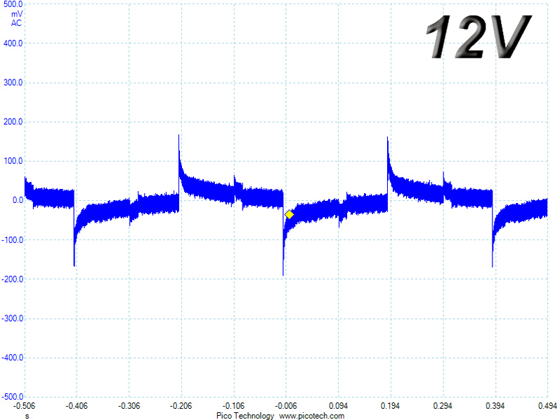
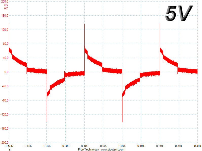
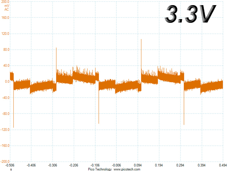
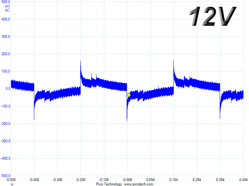
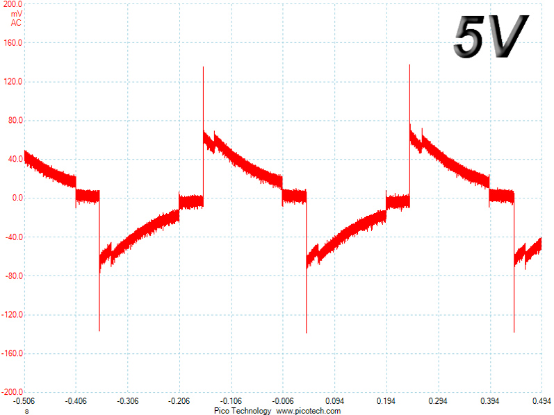
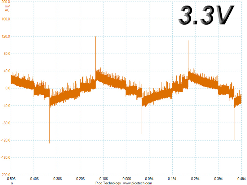
The transient response at +12V is decent. Performance isn't that good at 5V and 3.3V, while the 5VSB rail is probably the only one that manages to distinguish itself.
Below are the oscilloscope screenshots we took during Advanced Transient Response testing.
Transient Response at 20% Load
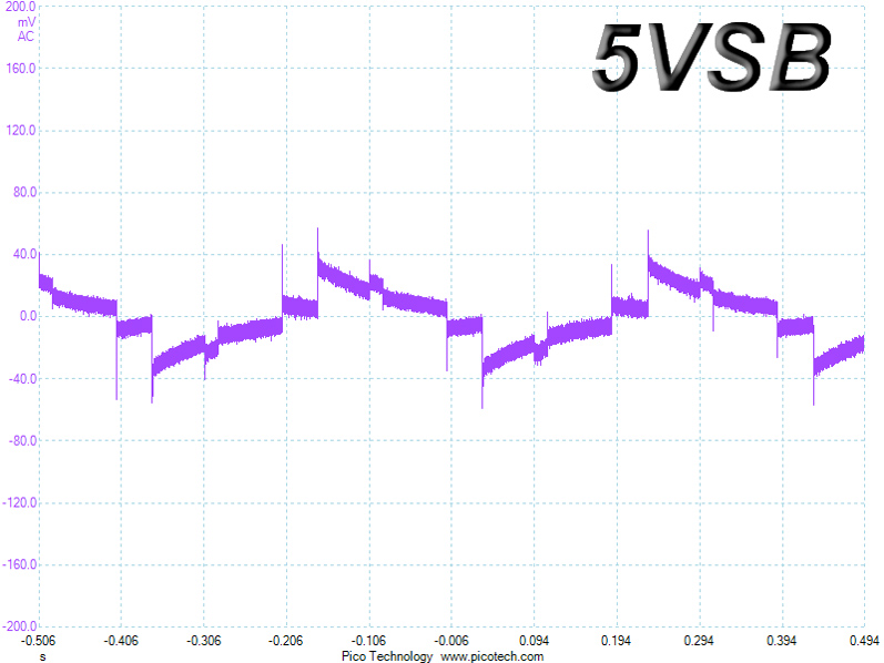
Transient Response at 50% Load
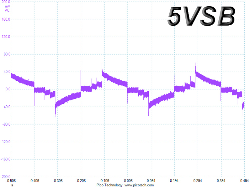
Turn-On Transient Tests
We measure the response of the PSU in simpler scenarios of transient load—during the power-on phase of the PSU—in the next set of tests. In the first test, we turn the PSU off, dial the maximum current the 5VSB can output, and switch the PSU on. In the second test, we dial the maximum load +12V can handle and start the PSU while the PSU is in standby mode. In the last test, while the PSU is completely switched off (we cut off power or switch the PSU off by flipping its on/off switch), we dial the maximum load the +12V rail can handle before switching the PSU on from the loader and restoring power. The ATX specification states that recorded spikes on all rails should not exceed 10% of their nominal values (e.g., +10% for 12V is 13.2V and 5.5V for 5V).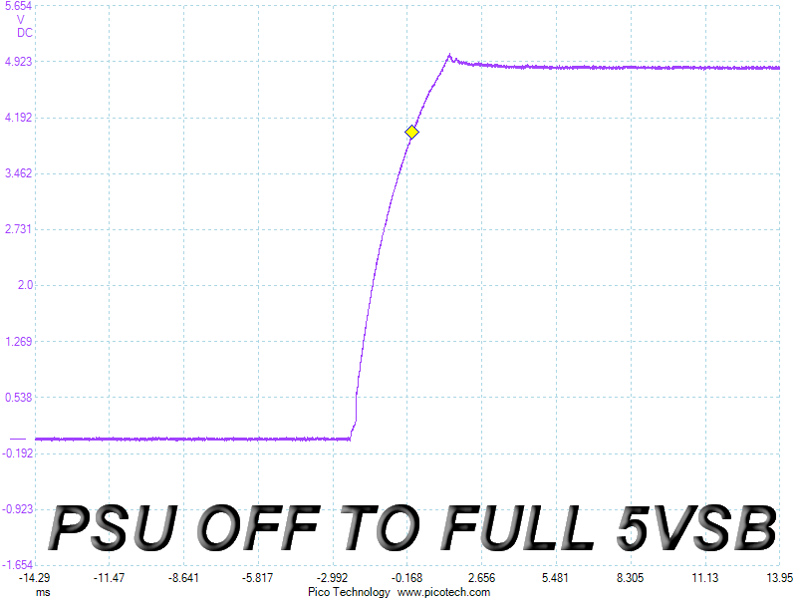
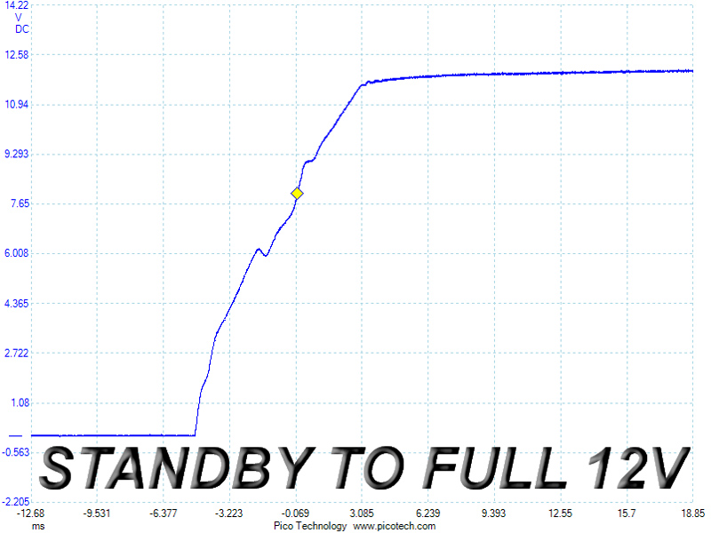
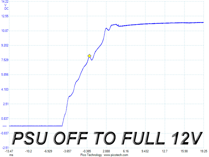
There's a small voltage overshoot at 5VSB, and the slopes in the next two tests don't look that nice; not a terrible result, it isn't very good either.
Jul 12th, 2025 01:12 CDT
change timezone
Latest GPU Drivers
New Forum Posts
- 'NVIDIA App' not usable offline? (8)
- Can you guess Which game it is? (222)
- What are you playing? (23920)
- RX 9070 XT freezing/locking up only on desktop, anyone else? (43)
- NVIDIA RTX PRO 6000 Workstation Runs Much Hotter Than 5090 FE (22)
- Quick charging your USB devicesUSB 3.2 Gen 2x2 Type-C® front-panel. (1)
- GTX 1050 GPU Owners Club (12)
- ASUS ProArt GeForce RTX 4060 Ti OC Edition 16GB GDDR6 Gaming - nvflash64 VBIOS mismatch (2)
- Will you buy a RTX 5090? (640)
- No offense, here are some things that bother me about your understanding of fans. (33)
Popular Reviews
- Fractal Design Epoch RGB TG Review
- Corsair FRAME 5000D RS Review
- Lexar NM1090 Pro 4 TB Review
- NVIDIA GeForce RTX 5050 8 GB Review
- NZXT N9 X870E Review
- Sapphire Radeon RX 9060 XT Pulse OC 16 GB Review - An Excellent Choice
- AMD Ryzen 7 9800X3D Review - The Best Gaming Processor
- Upcoming Hardware Launches 2025 (Updated May 2025)
- Our Visit to the Hunter Super Computer
- Chieftec Iceberg 360 Review
TPU on YouTube
Controversial News Posts
- Intel's Core Ultra 7 265K and 265KF CPUs Dip Below $250 (288)
- Some Intel Nova Lake CPUs Rumored to Challenge AMD's 3D V-Cache in Desktop Gaming (140)
- AMD Radeon RX 9070 XT Gains 9% Performance at 1440p with Latest Driver, Beats RTX 5070 Ti (131)
- NVIDIA Launches GeForce RTX 5050 for Desktops and Laptops, Starts at $249 (119)
- NVIDIA GeForce RTX 5080 SUPER Could Feature 24 GB Memory, Increased Power Limits (115)
- Microsoft Partners with AMD for Next-gen Xbox Hardware (105)
- Intel "Nova Lake‑S" Series: Seven SKUs, Up to 52 Cores and 150 W TDP (100)
- NVIDIA DLSS Transformer Cuts VRAM Usage by 20% (97)