 8
8
GamaKay LK75 Wireless Mechanical Keyboard Review
Software »Disassembly
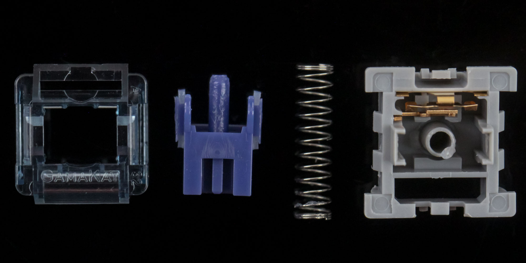
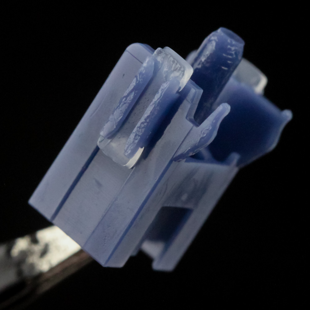
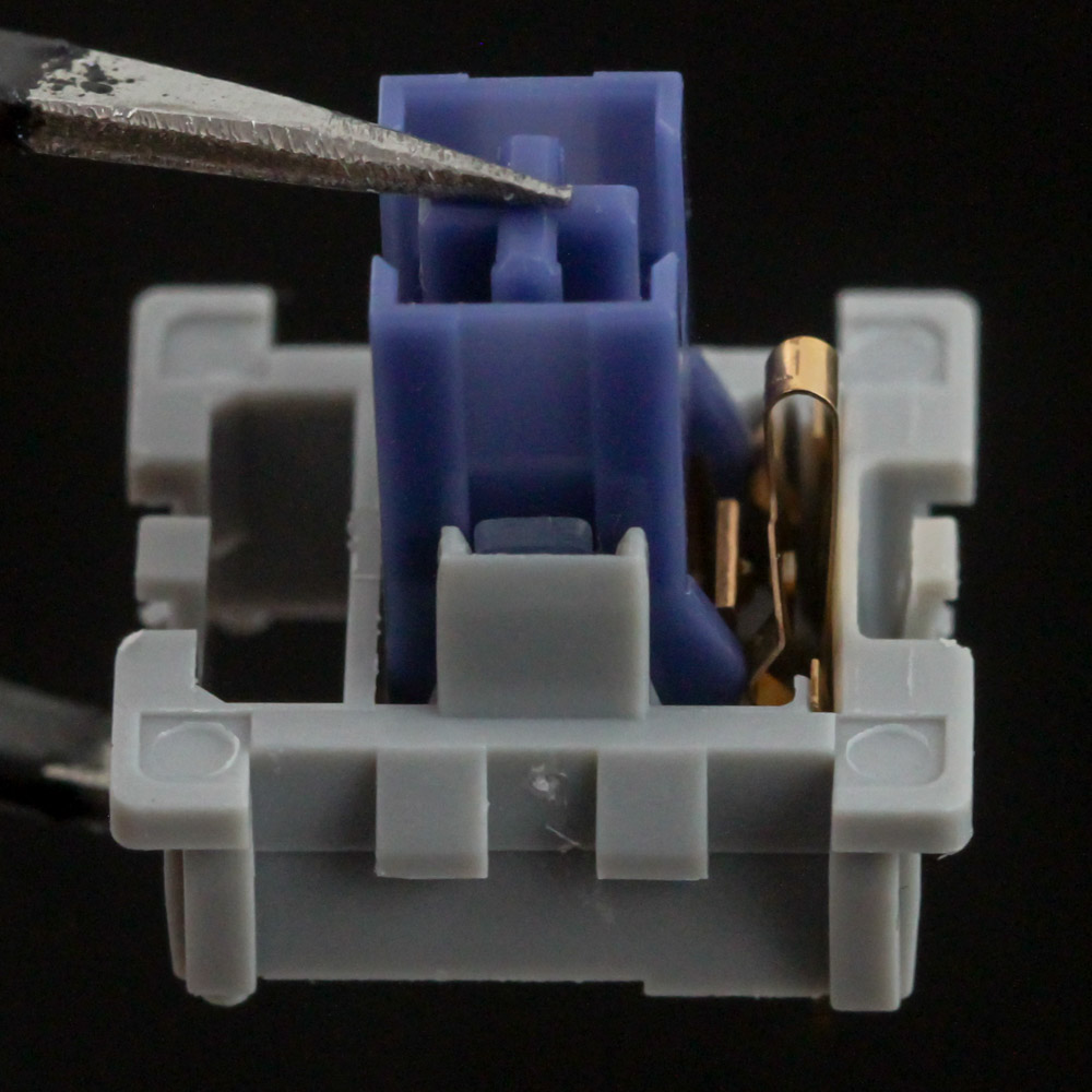
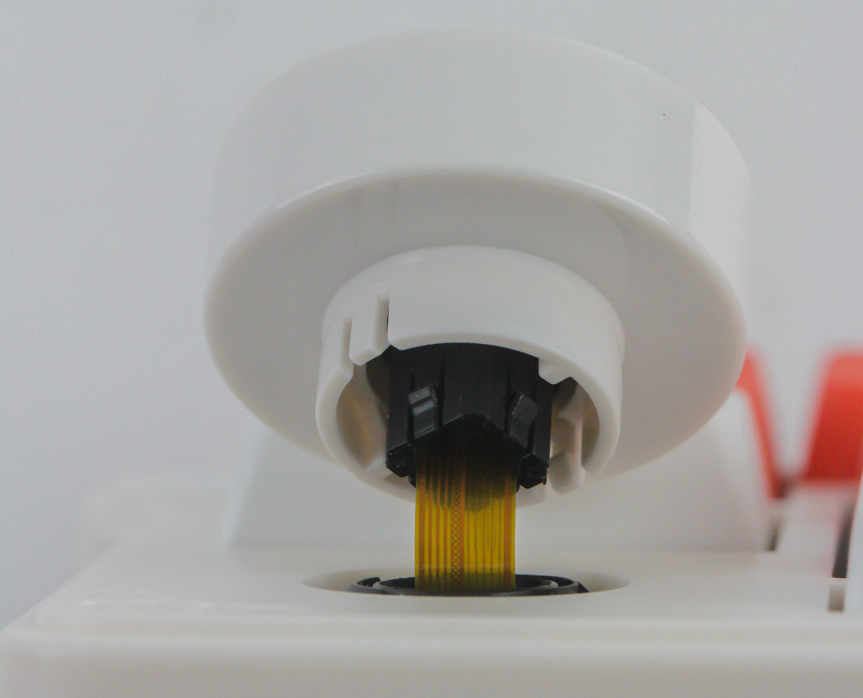
Given the hot-swappable switches here, I wanted to begin this section with a look inside the GamaKay Pegasus switches that came on this sample. This is a tactile switch with a pre-lubed stem and spring, and well lubed to where I don't expect to gain much from taking these apart for cleaning and re-lubing. It is also a silent switch in having a dampened bottom housing where the stem hits when bottoming out, but otherwise the switch design is quite similar to other such Cherry MX-style switches in that stem pushes the copper contacts in the bottom housing together to initiate switch actuation that is read by the microcontroller on the keyboard.
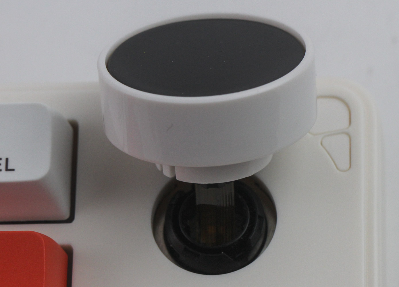
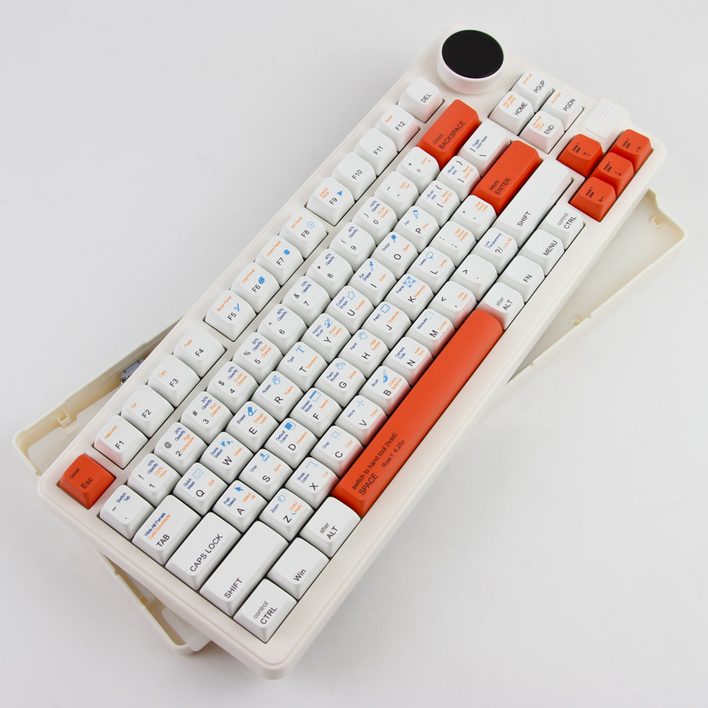
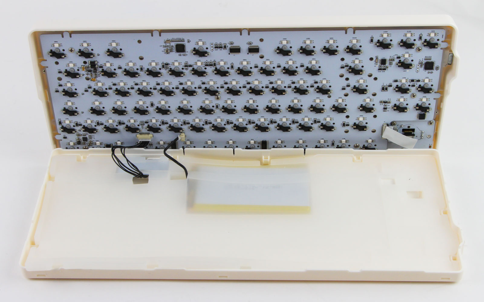
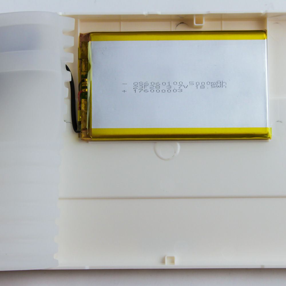
Normally with such two-piece plastic case keyboards that have a knob on the top, the first thing to do is remove the knob cover and then pull off the top panel. However, this one is complicated by having the LCD display also attached via a thin ribbon cable. I also observed that the knob cover is fully plastic, as are the connecting parts inside, so time will tell how well this lasts over time given there is currently a satisfying ratchety rotary motion. There is no easy way to remove the cable from this side although we do get a look at the button underneath you can press inwards, but thankfully GamaKay has gone with a top mount for the LK75 meaning the PCB/plate is connected to the top pieces rather than resting on the bottom. At this point, carefully place the knob back inside and use a thin, flat object to pry apart the interlocking plastic tabs in the case. The bottom panel comes loose enough to remove the two internal cables securing the daughter PCB and the battery to the primary PCB. Now we can see the thick silicone sheet placed between the PCB and the bottom panel as well as the relatively large 5000 mAh battery inside.
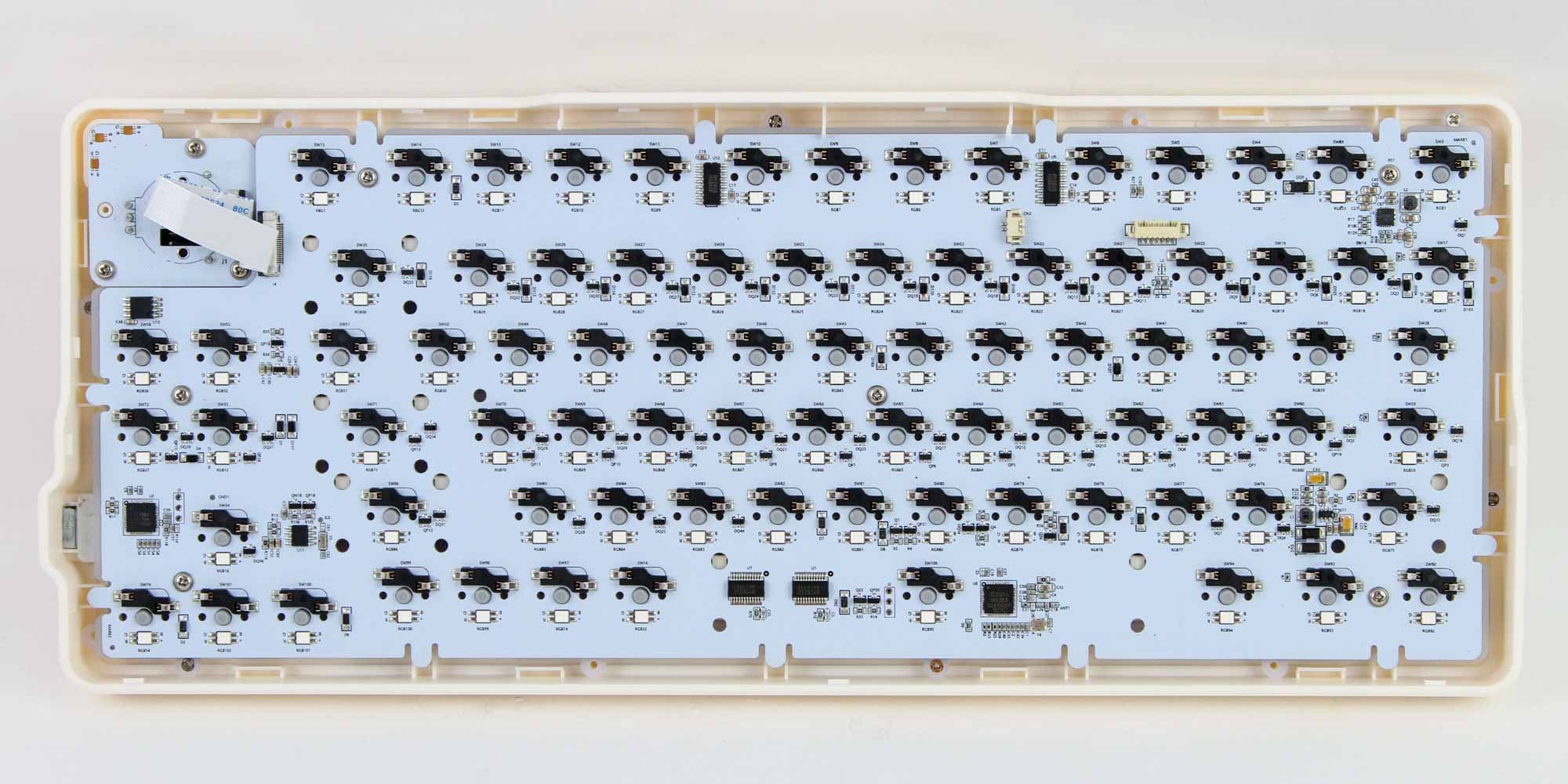
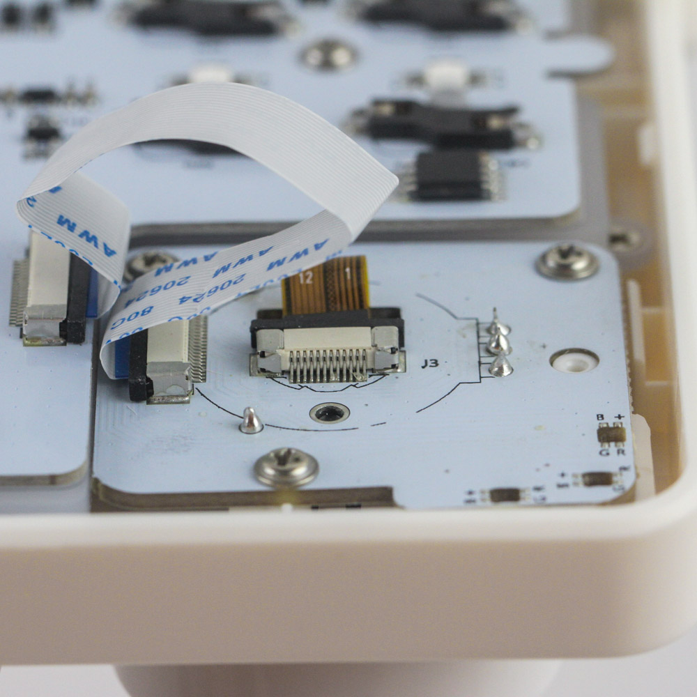
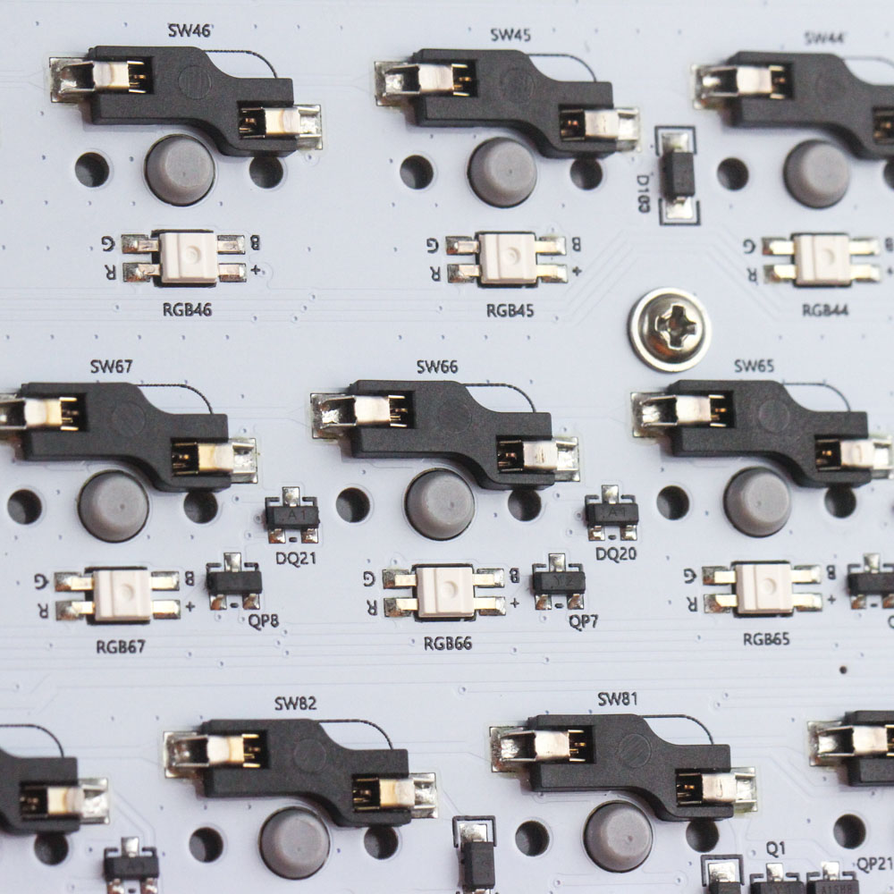
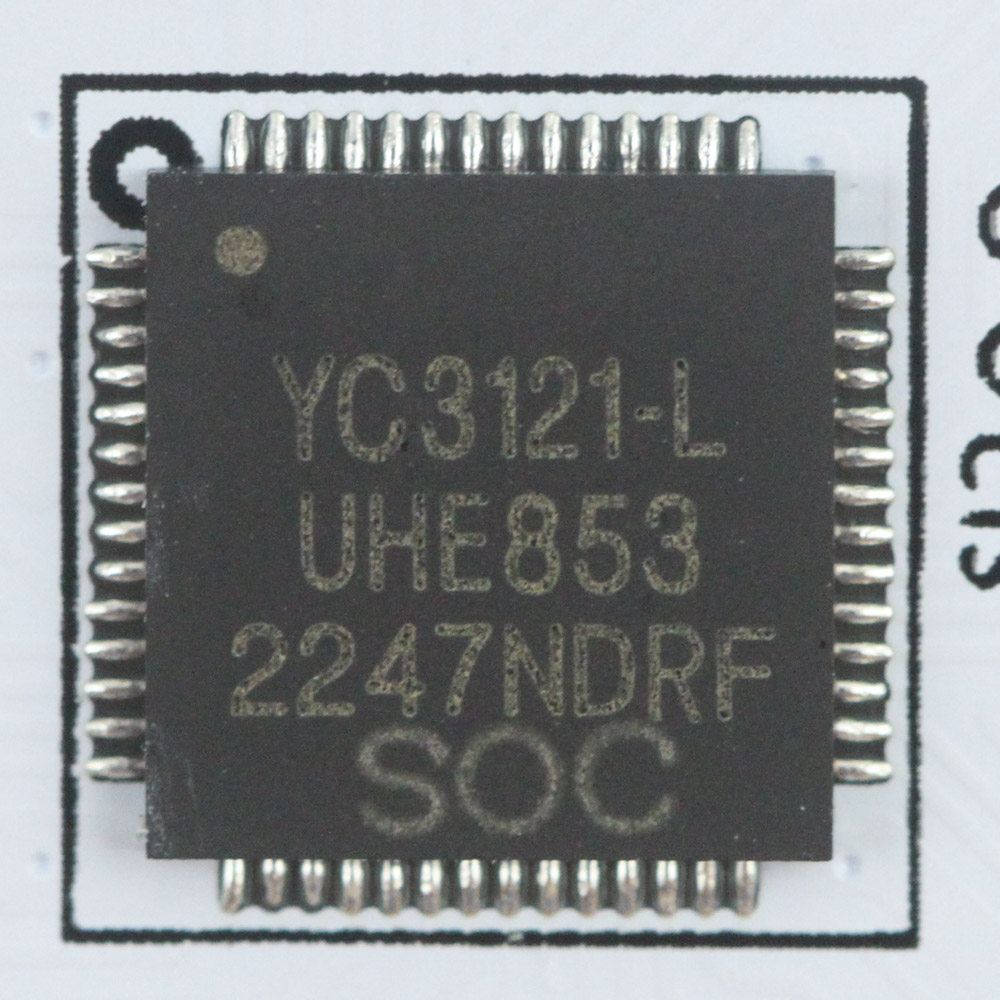
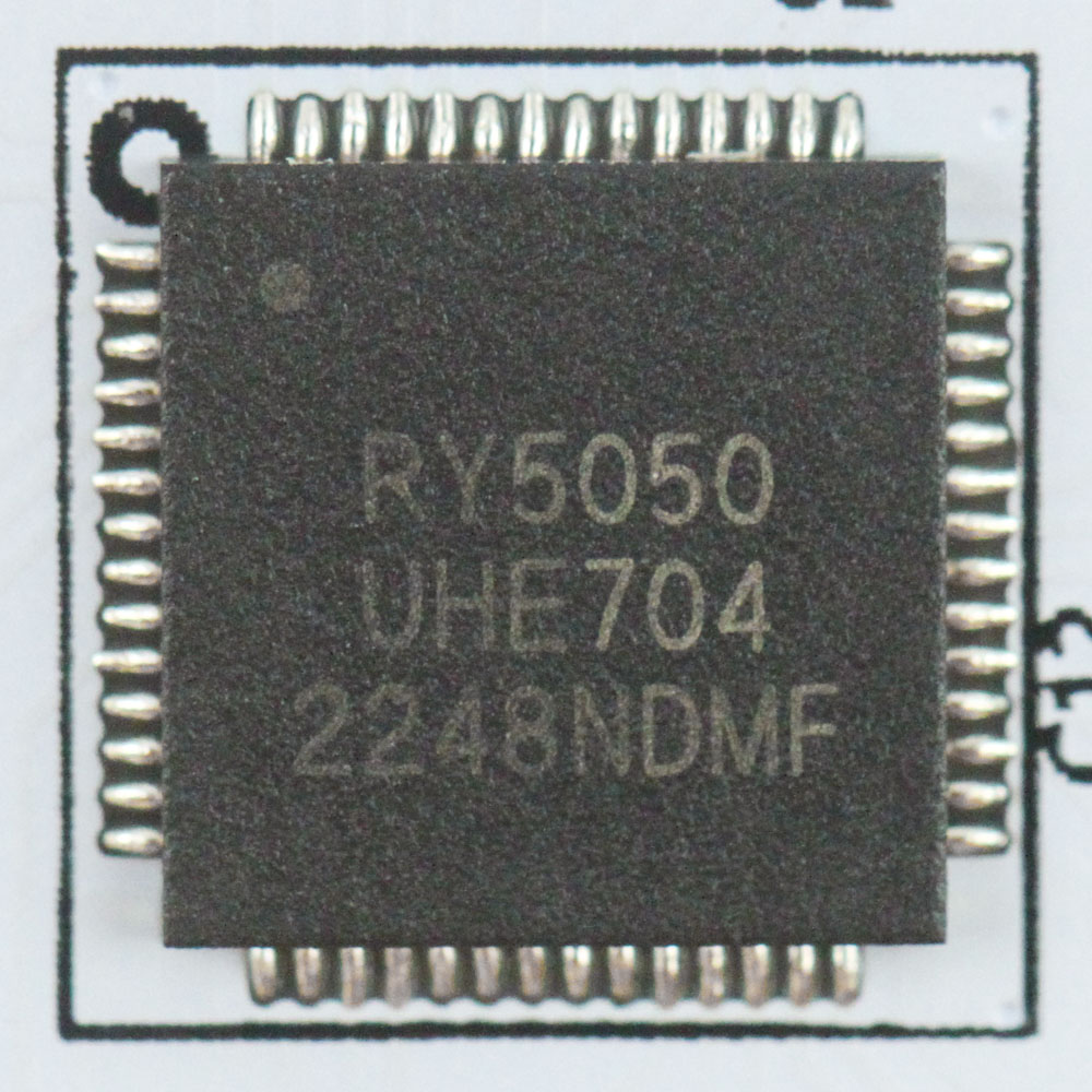
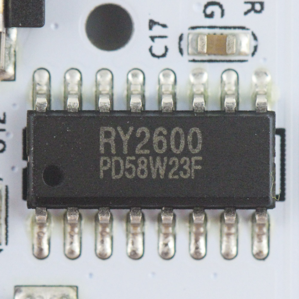
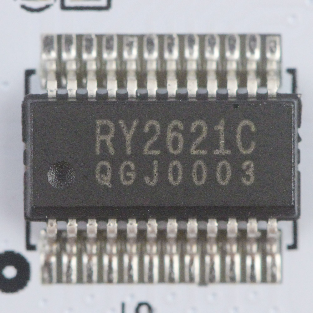
There is another daughter PCB which fits neatly into the cutout of the primary one and has two ribbon cables going back and forth—one for the rotary encoder and the other for the display. The white PCB is nice to see but probably just a coincidence here. There are unmarked hot-swap switch sockets in use as well as a YiChip YC3x-series hardware driver which is a 32-bit RISC architecture USB microcontroller as well as Bluetooth 5.0 transceiver. There are a few other harder-to-identify drivers here that might well be for LED control in addition to hosting a 2.4 GHz SoC. All the components, including the switch sockets, SMD LEDs, and capacitors, are soldered to a multi-layered PCB.
Before we move on, be advised that disassembly may void the warranty and that TechPowerUp is not liable for any damages incurred if you decide to go ahead and do so anyway.
Jul 4th, 2025 03:20 CDT
change timezone
Latest GPU Drivers
New Forum Posts
- Do you use Linux? (669)
- They're b...a....c....k.... (20)
- RDNA 4 Fine Wine? (HUB Vid) (58)
- Gigabyte graphic cards - TIM gel SLIPPAGE problem (128)
- Will you buy a RTX 5090? (616)
- [GPU-Z Test Build] New Kernel Driver, Everyone: Please Test (38)
- What Windows is overall the best to you and why? (272)
- How often do you (re)install your OS? (206)
- What would you buy? (53)
- Need help with X-Fi xtremegamer Fatal1ty card (1)
Popular Reviews
- Fractal Design Scape Review - Debut Done Right
- ASUS ROG Crosshair X870E Extreme Review
- Crucial T710 2 TB Review - Record-Breaking Gen 5
- PowerColor ALPHYN AM10 Review
- Sapphire Radeon RX 9060 XT Pulse OC 16 GB Review - An Excellent Choice
- Upcoming Hardware Launches 2025 (Updated May 2025)
- AMD Ryzen 7 9800X3D Review - The Best Gaming Processor
- Sapphire Radeon RX 9070 XT Nitro+ Review - Beating NVIDIA
- SCHENKER KEY 18 Pro (E25) Review - Top-Tier Contender
- AVerMedia CamStream 4K Review
TPU on YouTube
Controversial News Posts
- Intel's Core Ultra 7 265K and 265KF CPUs Dip Below $250 (288)
- NVIDIA Grabs Market Share, AMD Loses Ground, and Intel Disappears in Latest dGPU Update (212)
- Some Intel Nova Lake CPUs Rumored to Challenge AMD's 3D V-Cache in Desktop Gaming (140)
- NVIDIA GeForce RTX 5080 SUPER Could Feature 24 GB Memory, Increased Power Limits (115)
- Microsoft Partners with AMD for Next-gen Xbox Hardware (105)
- NVIDIA Launches GeForce RTX 5050 for Desktops and Laptops, Starts at $249 (105)
- Intel "Nova Lake‑S" Series: Seven SKUs, Up to 52 Cores and 150 W TDP (100)
- NVIDIA DLSS Transformer Cuts VRAM Usage by 20% (97)