 5
5
Kingwin Stryker Fanless 500 W Review
Ripple Measurements »Advanced Transient Response Tests
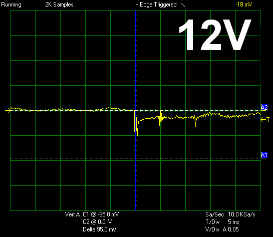
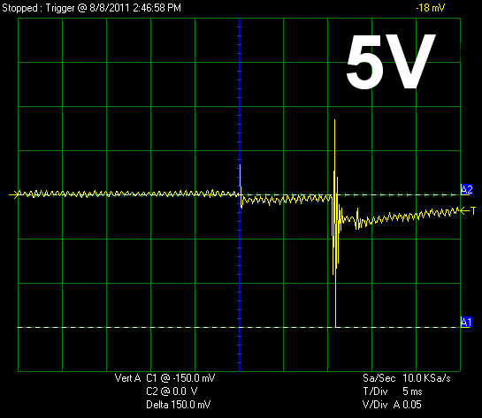
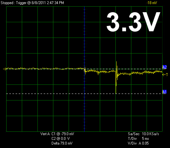
In these tests we monitor the response of the PSU in two different scenarios. First a transient load (11A at +12V, 5A at 5V, 6A at 3.3V and 0.5A at 5VSB) is applied for 50 ms to the PSU, while the latter is working at a 20% load state. In the second scenario the PSU, while working with 50% load, is hit by the same transient load. In both tests, we measure the voltage drops that the transient load causes, using our oscilloscope. In any case voltages should remain within the regulation limits specified by the ATX specification. We must stress here, that the above tests are crucial, since they simulate transient loads that a PSU is very likely to handle (e.g. starting of a RAID array, an instant 100% load of CPU/VGAs etc.) We call these tests “Advanced Transient Response Tests” and they are designed to be very tough to master, especially for PSUs with capacities lower than 500W.| Advanced Transient Response 20% | ||||
|---|---|---|---|---|
| Voltage | Before | After | Change | Pass/Fail |
| 12 V | 12.216V | 12.121V | 0.78% | Pass |
| 5 V | 5.154V | 5.004V | 2.91% | Pass |
| 3.3 V | 3.373V | 3.294V | 2.34% | Pass |
| 5VSB | 5.091V | 5.064V | 0.53% | Pass |
| Advanced Transient Response 50% | ||||
|---|---|---|---|---|
| Voltage | Before | After | Change | Pass/Fail |
| 12 V | 12.159V | 12.076V | 0.68% | Pass |
| 5 V | 5.082V | 4.932V | 2.95% | Pass |
| 3.3 V | 3.320V | 3.208V | 3.37% | Pass |
| 5VSB | 5.064V | 5.038V | 1.05% | Pass |
Even though its small capacity is a huge handicap in these tests, the STR-500 didn't have a problem passing all of them successfully. Voltage drops were within 5% at all time and the higher than normal voltage levels on all rails greatly helped in keeping the rails away from the ATX voltage regulation's lower limits.
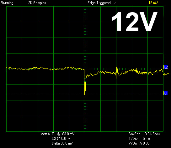
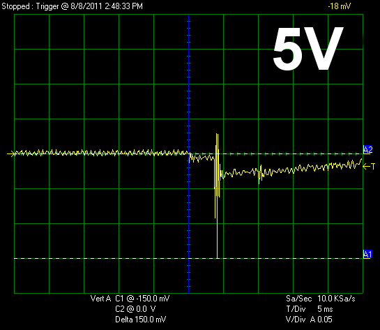
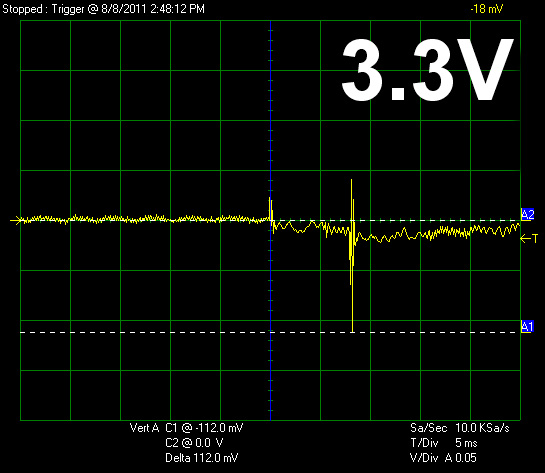
Below you will find the oscilloscope screenshots that we took during Advanced Transient Response Testing.
Transient Response at 20% Load
Transient Response at 50% Load
Turn-On Transient Tests
In the next set of tests we measure the response of the PSU in simpler scenarios of transient loads, during the turn on phase of the PSU. In the first test we turn off the PSU, dial 2.5A load at 5VSB and then switch on the PSU. In the second test, while the PSU is in standby, we dial the maximum load that +12V can handle and we start the PSU. In the last test, while the PSU is completely switched off (we cut off power or switch off the PSU's On/Off switch), we dial the maximum load that +12V can handle and then we switch on the PSU from the loader and we restore power. The ATX specification states that recorded spikes on all rails should not exceed 10% of their nominal values (e.g. +10% for 12V is 13.2V and for 5V is 5.5V).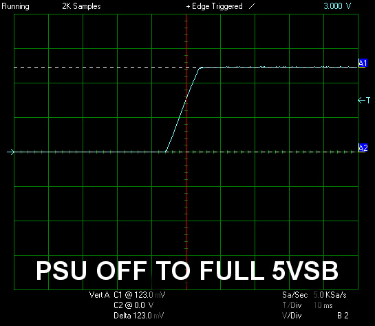
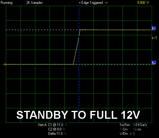
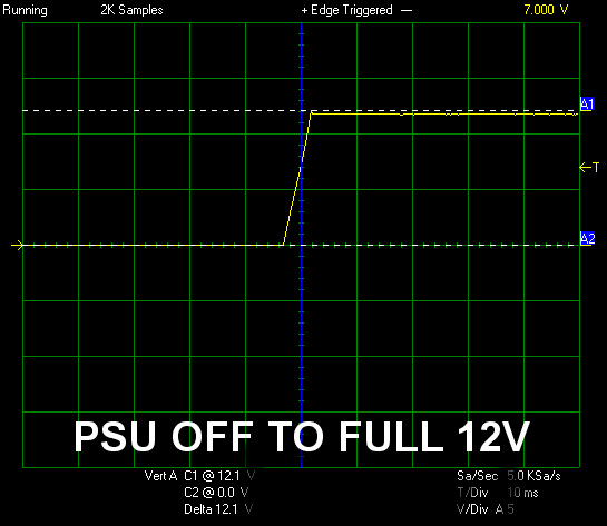
We noticed only a tiny voltage overshoot at "PSU Off to Full 12V" test. In the remaining two tests the rails did not register any voltage spikes. Overall the unit performed excellent here and the rise time on all three tests is within ATX spec range (0.2 - 20 ms).
Jul 5th, 2025 18:36 CDT
change timezone
Latest GPU Drivers
New Forum Posts
- [GPU-Z Test Build] New Kernel Driver, Everyone: Please Test (69)
- How do you view TPU & the internet in general? (With poll) (80)
- EVGA XC GTX 1660 Ti 8GB ROM (11)
- Rx580 subsystem id (0)
- What are you playing? (23893)
- Do you use Linux? (677)
- Optane performance on AMD vs Intel (58)
- Frametime spikes and stuttering after switching to AMD CPU? (521)
- Stalker 2 is looking great. (187)
- b550m aorus elite not posting with new ram (7)
Popular Reviews
- NVIDIA GeForce RTX 5050 8 GB Review
- Fractal Design Scape Review - Debut Done Right
- Crucial T710 2 TB Review - Record-Breaking Gen 5
- ASUS ROG Crosshair X870E Extreme Review
- PowerColor ALPHYN AM10 Review
- Sapphire Radeon RX 9060 XT Pulse OC 16 GB Review - An Excellent Choice
- Upcoming Hardware Launches 2025 (Updated May 2025)
- AMD Ryzen 7 9800X3D Review - The Best Gaming Processor
- Sapphire Radeon RX 9070 XT Nitro+ Review - Beating NVIDIA
- NVIDIA GeForce RTX 5060 8 GB Review
TPU on YouTube
Controversial News Posts
- Intel's Core Ultra 7 265K and 265KF CPUs Dip Below $250 (288)
- NVIDIA Grabs Market Share, AMD Loses Ground, and Intel Disappears in Latest dGPU Update (212)
- Some Intel Nova Lake CPUs Rumored to Challenge AMD's 3D V-Cache in Desktop Gaming (140)
- NVIDIA GeForce RTX 5080 SUPER Could Feature 24 GB Memory, Increased Power Limits (115)
- Microsoft Partners with AMD for Next-gen Xbox Hardware (105)
- NVIDIA Launches GeForce RTX 5050 for Desktops and Laptops, Starts at $249 (105)
- AMD Radeon RX 9070 XT Gains 9% Performance at 1440p with Latest Driver, Beats RTX 5070 Ti (102)
- Intel "Nova Lake‑S" Series: Seven SKUs, Up to 52 Cores and 150 W TDP (100)