 12
12
Andyson Titanium N 700 W Review
Ripple Measurements »Advanced Transient Response Tests
In these tests, we monitor the response of the PSU in two different scenarios. First, a transient load (10 A at +12V, 5 A at 5V, 5 A at 3.3V, and 0.5 A at 5VSB) is applied to the PSU for 200 ms while the latter is working at 20% load. In the second scenario, the PSU, while working at 50% load, is hit by the same transient load. In both tests, we measure the voltage drops the transient load causes using our oscilloscope. The voltages should remain within the regulation limits defined by the ATX specification. We must stress here that these tests are crucial since they simulate transient loads a PSU is very likely to handle (e.g., booting a RAID array, an instant 100% load of CPU/VGAs, etc.). We call these tests Advanced Transient Response tests, and they are designed to be very tough to master, especially for a PSU with a capacity below 500 W.| Advanced Transient Response 20% | ||||
|---|---|---|---|---|
| Voltage | Before | After | Change | Pass/Fail |
| 12 V | 12.134V | 11.884V | 2.06% | Pass |
| 5 V | 5.037V | 4.970V | 1.33% | Pass |
| 3.3 V | 3.328V | 3.247V | 2.43% | Pass |
| 5VSB | 5.023V | 4.967V | 1.11% | Pass |
| Advanced Transient Response 50% | ||||
|---|---|---|---|---|
| Voltage | Before | After | Change | Pass/Fail |
| 12 V | 12.109V | 12.022V | 0.72% | Pass |
| 5 V | 5.020V | 4.959V | 1.22% | Pass |
| 3.3 V | 3.309V | 3.226V | 2.51% | Pass |
| 5VSB | 5.000V | 4.948V | 1.04% | Pass |
Deviations on the +12V rail were about 2% higher in the first test because the main switchers operate in PWM mode at light loads, which slows their response times. Deviations were very well controlled in all other tests, and even the 3.3V rail stayed within 3%. All in all, the Andyson Titanium unit performed pretty well in these tests.
Below are the oscilloscope screenshots we took during Advanced Transient Response testing.
Transient Response at 20% Load
Transient Response at 50% Load
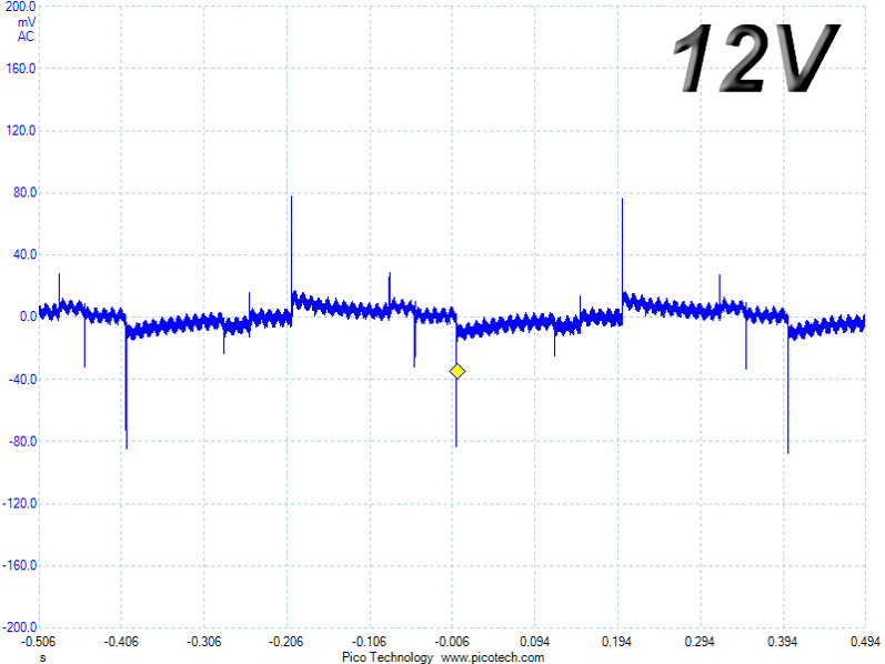
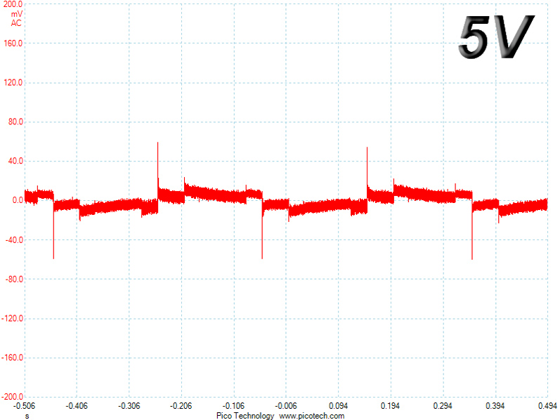
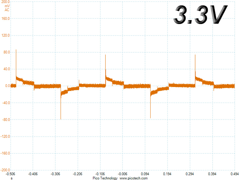
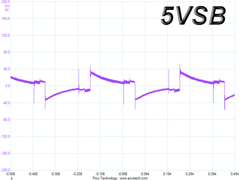
Turn-On Transient Tests
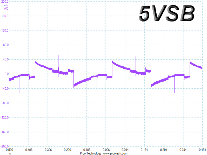
We measure the response of the PSU in simpler scenarios of transient load—during the power-on phase of the PSU—in the next set of tests. In the first test, we turn the PSU off, dial the maximum current the 5VSB can produce, and switch on the PSU. In the second test, we dial the maximum load +12V can handle and start the PSU while the PSU is in standby mode. In the last test, while the PSU is completely switched off (we cut off power or switch the PSU off by flipping its on/off switch), we dial the maximum load the +12V rail can handle before switching the PSU on from the loader and restoring power. The ATX specification states that recorded spikes on all rails should not exceed 10% of their nominal values (e.g., +10% for 12V is 13.2V and 5.5V for 5V).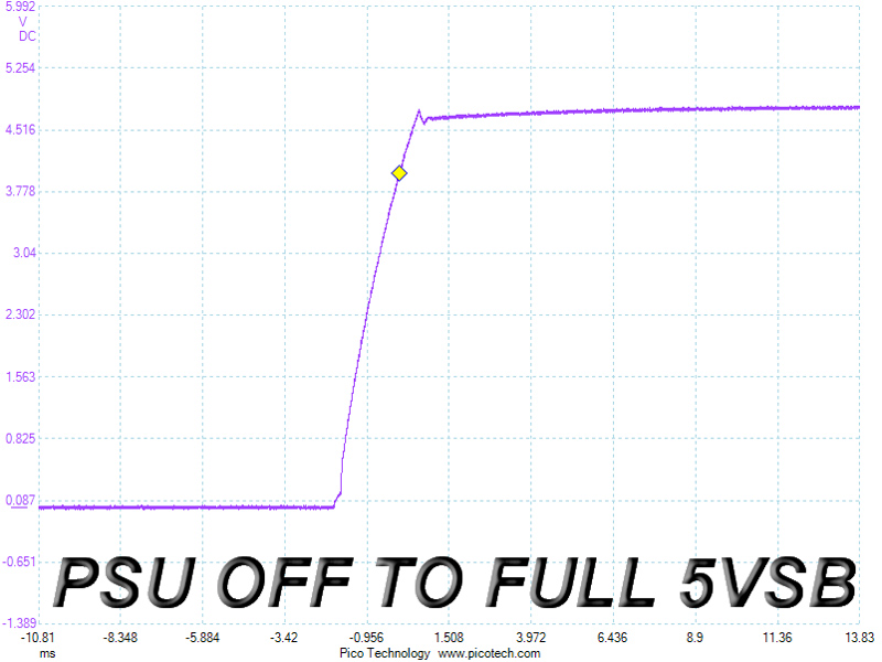
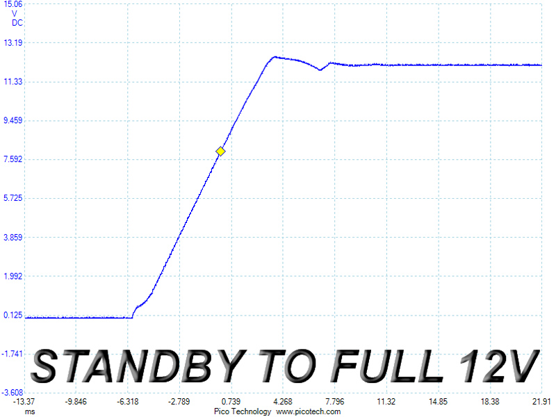
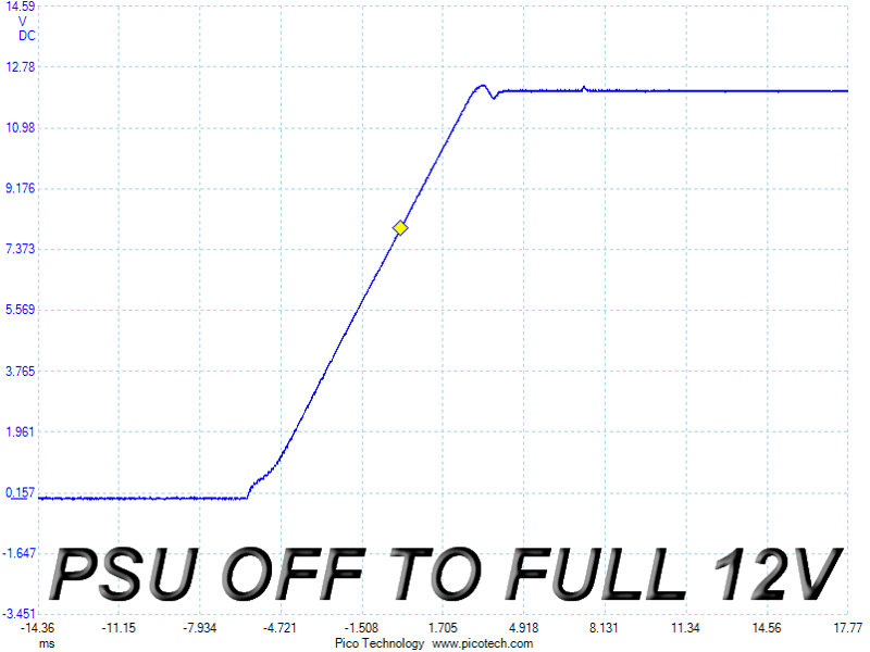
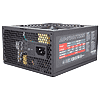
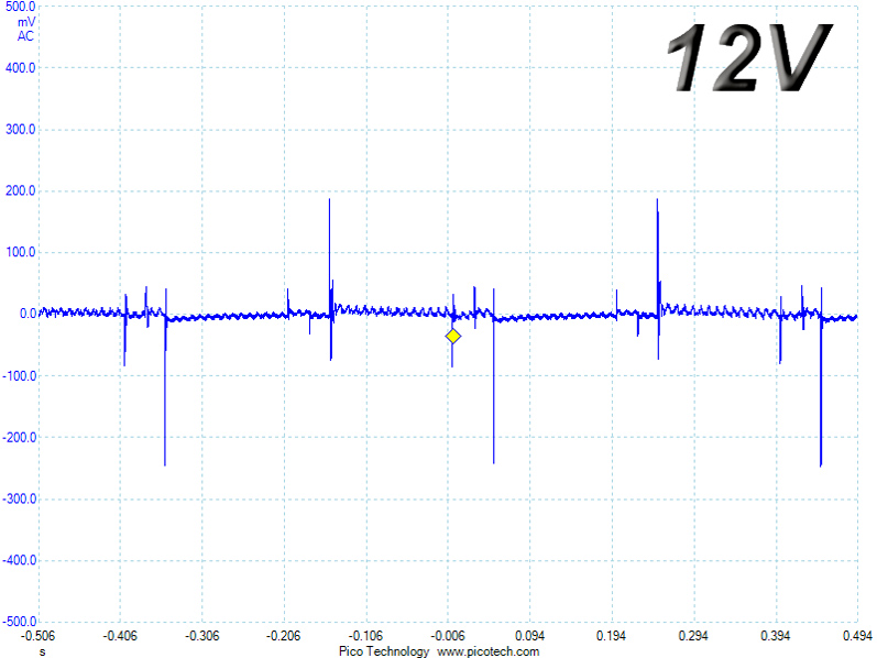
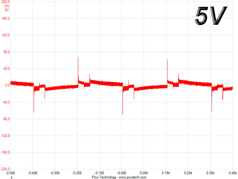
We noticed a minor spike at 5VSB, and there were small steps, both up and downs, in the +12V waveform; that is, before its voltage settled down. None of those spikes should worry you, though, since all of them peaked at well below the ATX specification's corresponding limits. As you can see in all three tests, the waveform also ramps up smoothly, and its rise time was within the specified range (0.2 - 20 ms).
Jul 14th, 2025 15:56 CDT
change timezone
Latest GPU Drivers
New Forum Posts
- AMD 7Ghz? This keeps popping up on my feeds! (6)
- Stupid things one has done with hardware (49)
- No offense, here are some things that bother me about your understanding of fans. (111)
- Choosing the right motherboard (5)
- Best motherboards for XP gaming (151)
- Which CPU to Choose for a 7900 XT? Ryzen 7 7700 or Ryzen 5 9600X? (43)
- Bent pins on an AM5 mobo, any way to test them and also find which ones were on the schematic? (6)
- i7 2860QM how to raise power limit? (20)
- Arc 770a 16gb money pit (9)
- Frametime spikes and stuttering after switching to AMD CPU? (572)
Popular Reviews
- Lexar NM1090 Pro 4 TB Review
- Our Visit to the Hunter Super Computer
- MSI GeForce RTX 5060 Gaming OC Review
- Fractal Design Epoch RGB TG Review
- NVIDIA GeForce RTX 5050 8 GB Review
- Corsair FRAME 5000D RS Review
- Sapphire Radeon RX 9060 XT Pulse OC 16 GB Review - An Excellent Choice
- Chieftec Iceberg 360 Review
- AMD Ryzen 7 9800X3D Review - The Best Gaming Processor
- Upcoming Hardware Launches 2025 (Updated May 2025)
TPU on YouTube
Controversial News Posts
- Intel's Core Ultra 7 265K and 265KF CPUs Dip Below $250 (288)
- Some Intel Nova Lake CPUs Rumored to Challenge AMD's 3D V-Cache in Desktop Gaming (140)
- AMD Radeon RX 9070 XT Gains 9% Performance at 1440p with Latest Driver, Beats RTX 5070 Ti (131)
- NVIDIA Launches GeForce RTX 5050 for Desktops and Laptops, Starts at $249 (122)
- NVIDIA GeForce RTX 5080 SUPER Could Feature 24 GB Memory, Increased Power Limits (115)
- Microsoft Partners with AMD for Next-gen Xbox Hardware (105)
- Intel "Nova Lake‑S" Series: Seven SKUs, Up to 52 Cores and 150 W TDP (100)
- NVIDIA DLSS Transformer Cuts VRAM Usage by 20% (97)