 25
25
ASUS ROG Claymore II Review - Three Keyboards in One!
Disassembly: Part 2 »Disassembly: Part 1

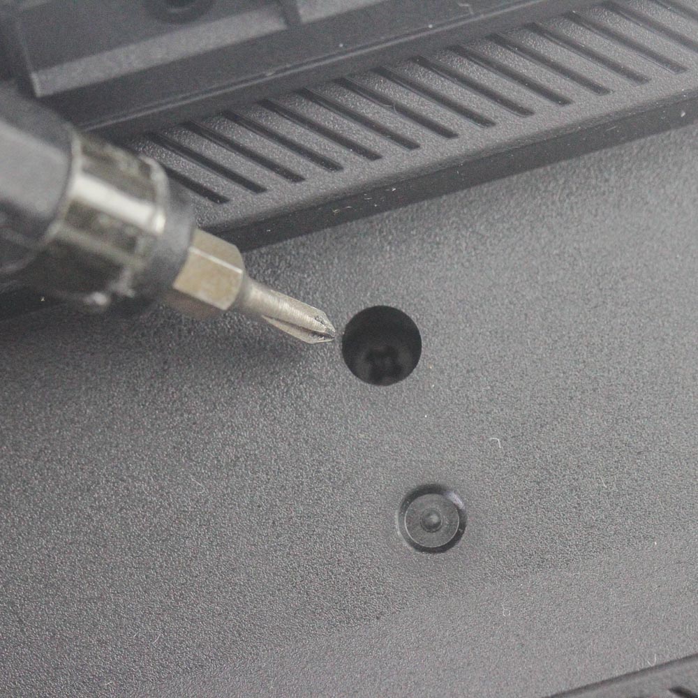
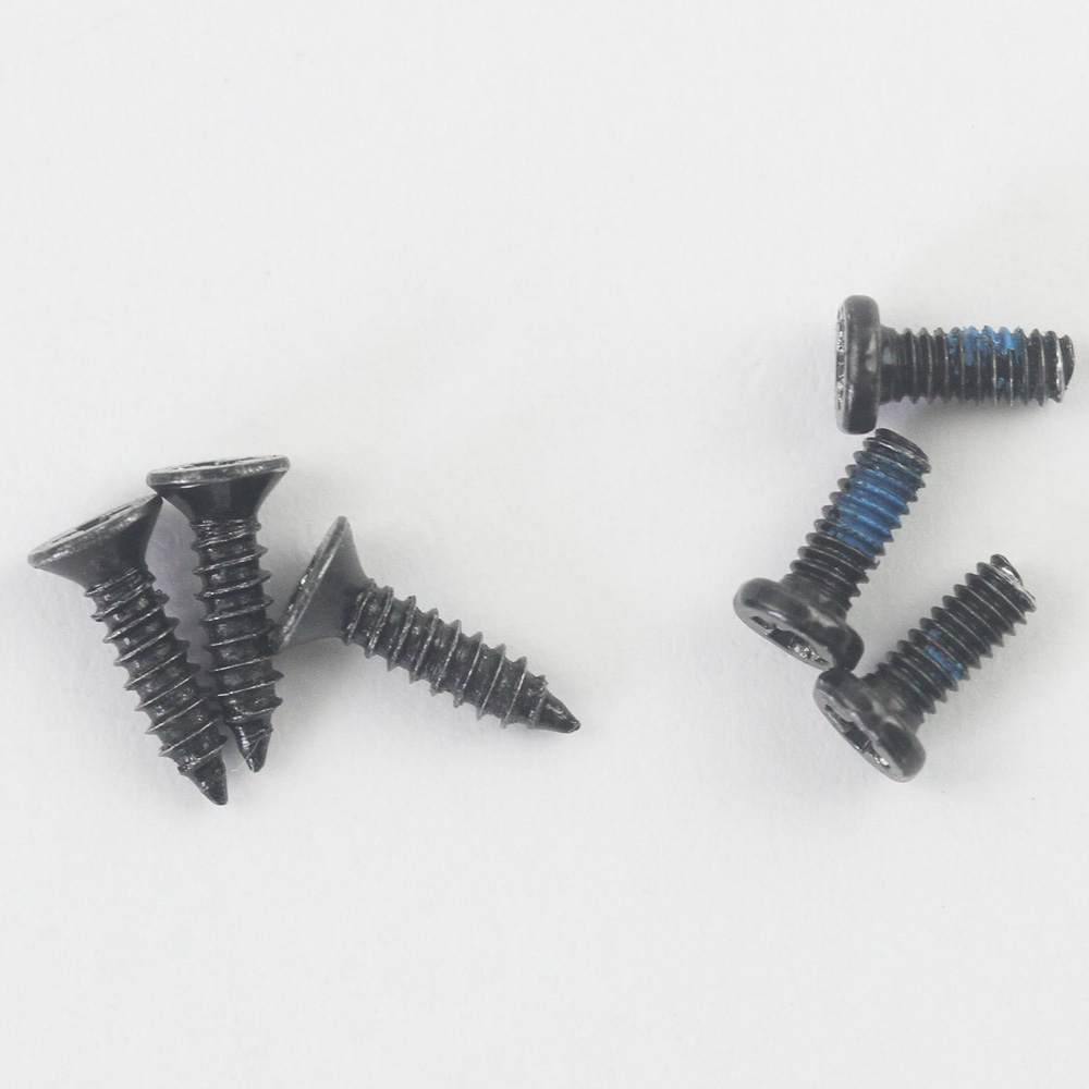
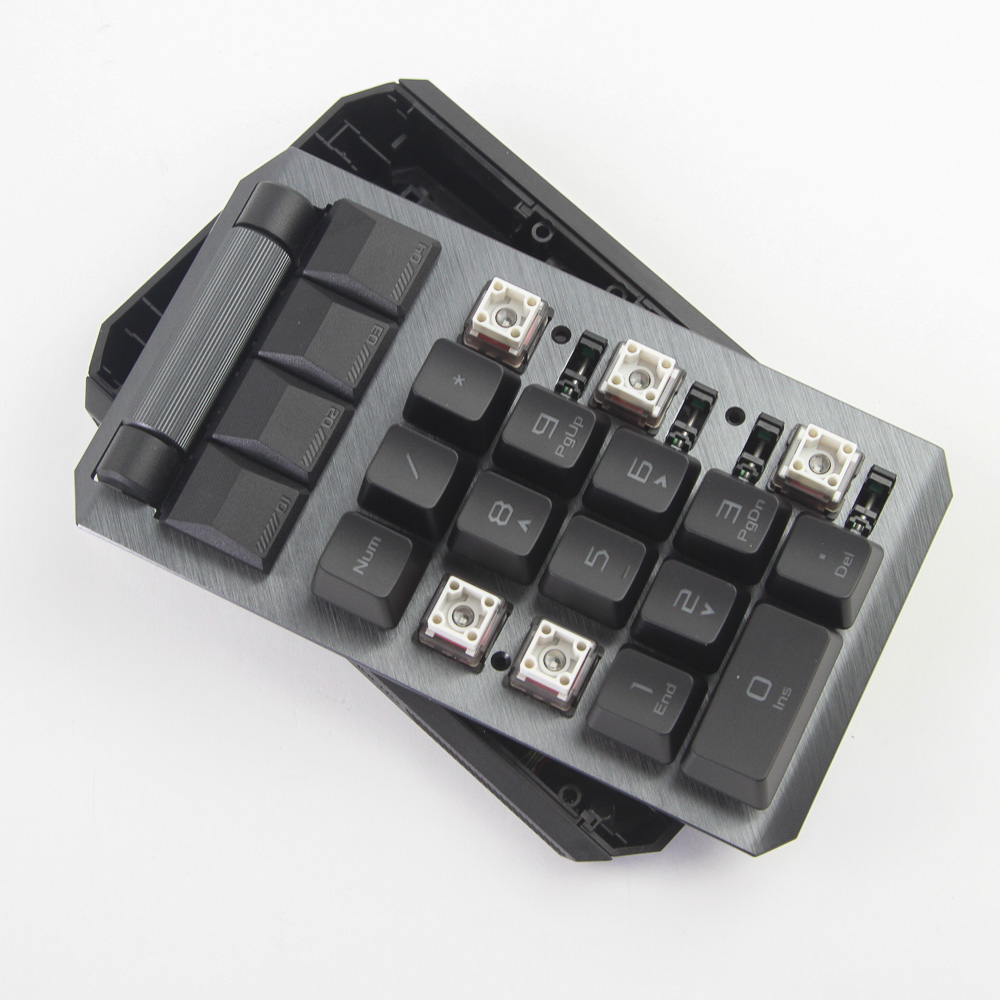
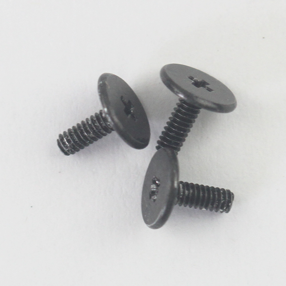
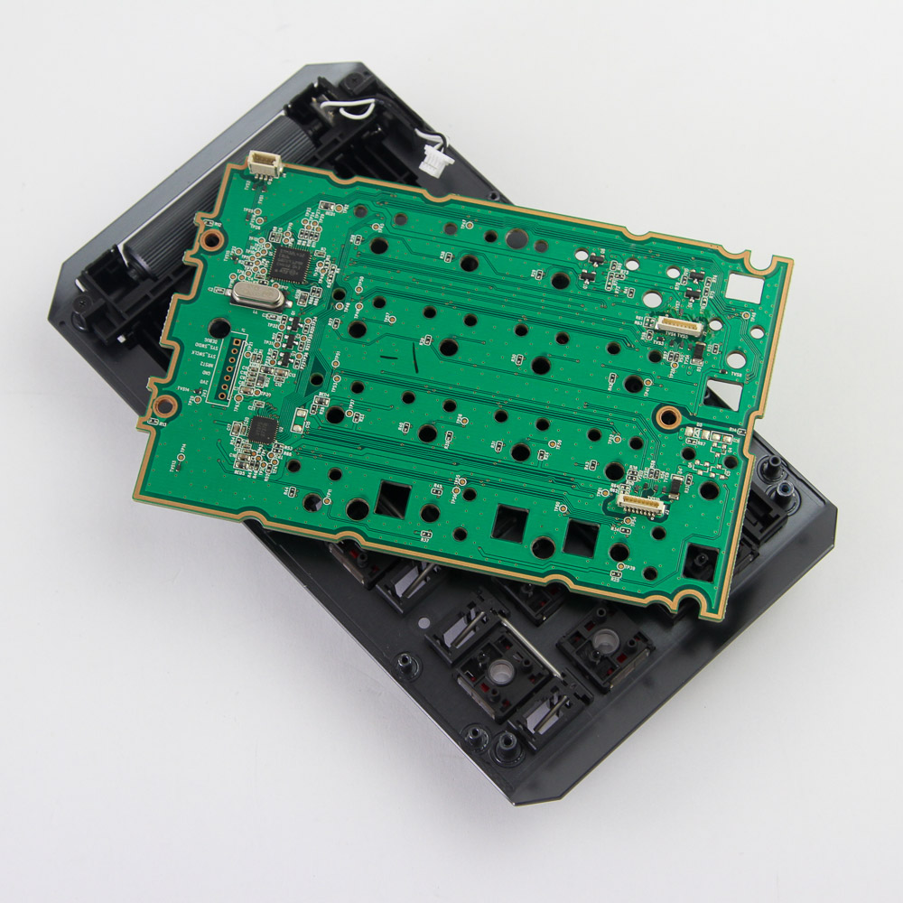
Hold on to your seats—this is a two-part disassembly for the first and hopefully last time ever! Given its smaller size, let's begin with the numpad. Three Phillips head screws underneath keycaps on the front need to be removed as seen above, as do three more hidden screws underneath the rubber pads on the back and the sole foot. Once done, the top aluminium frame can be lifted off the bottom plastic case panel.
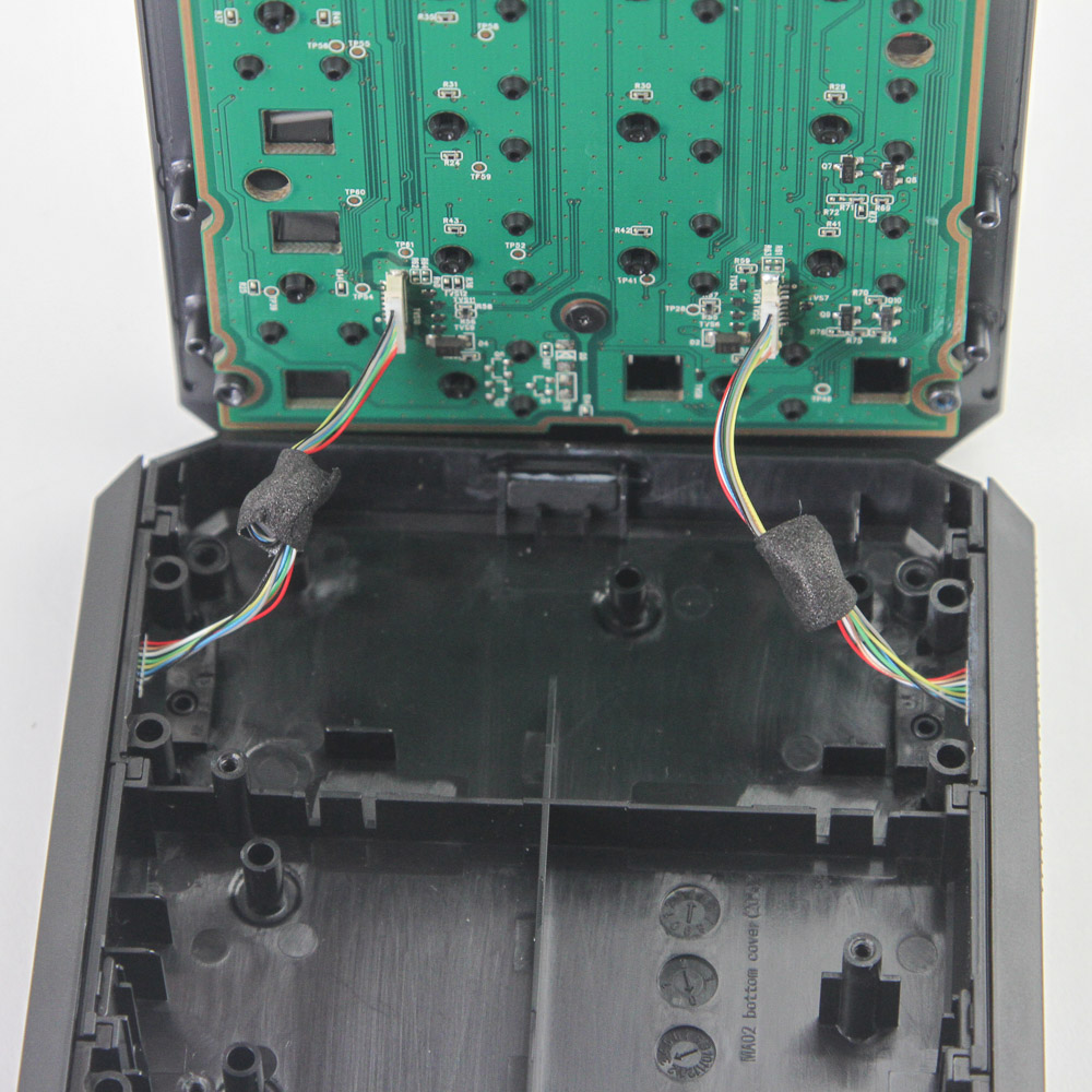
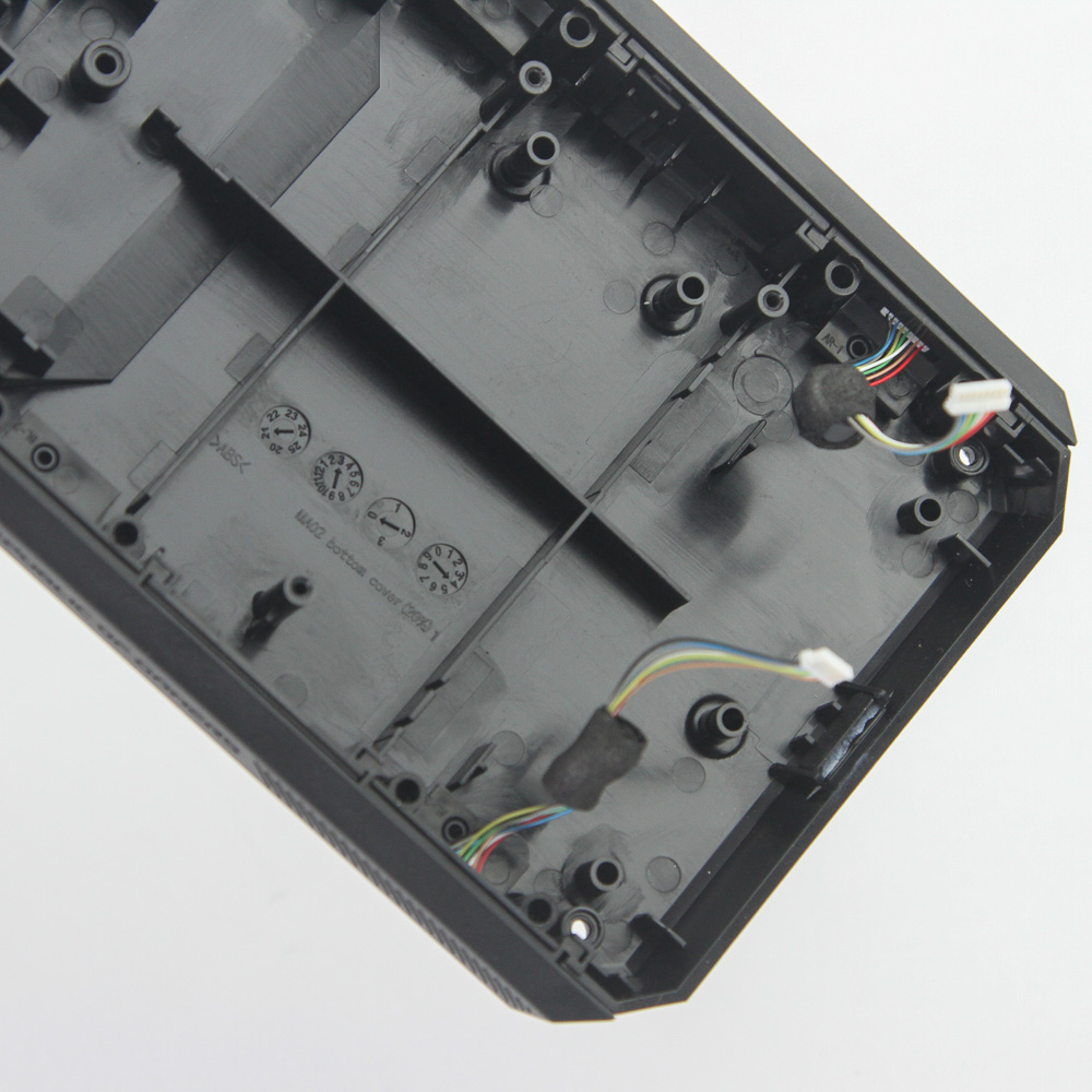
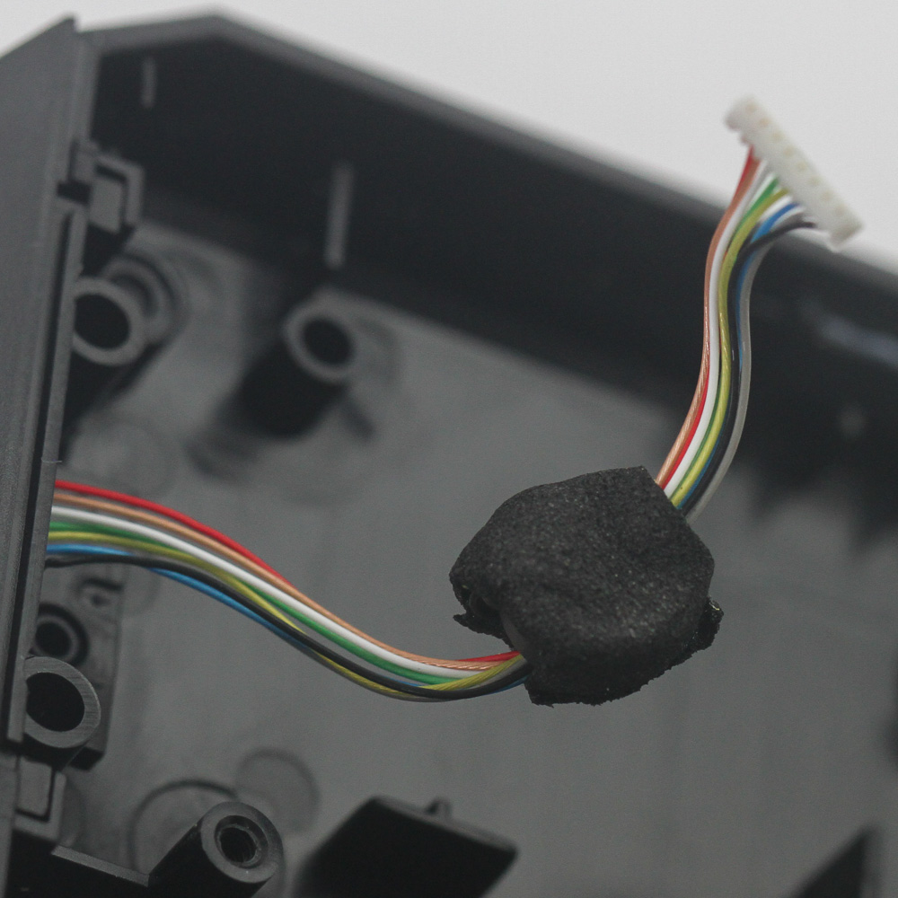
Do so carefully, though, since two short cables connect the side pads to the PCB. These are how the numpad connects to the keyboard on either side, so carefully dislodge the cables before completely separating the two main pieces. There is a lot to see here still, but let's start with the PCB, which is on the aluminium frame.
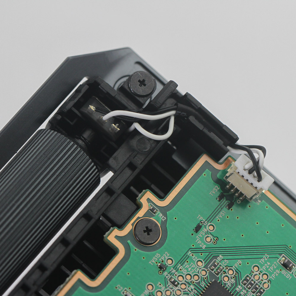
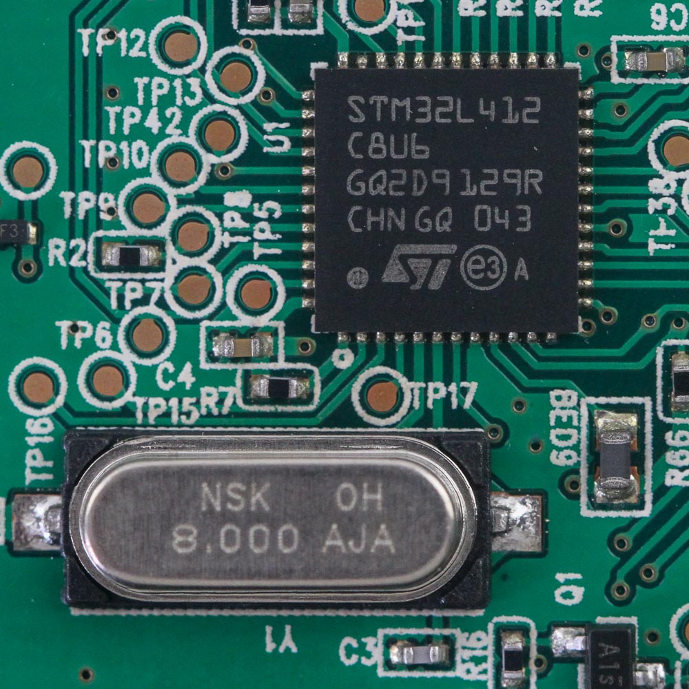
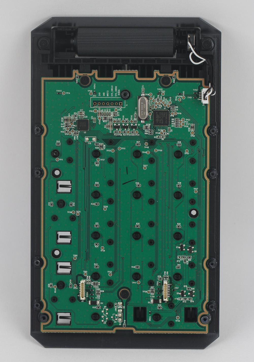
The volume wheel is tied to a rotary encoder, which is connected to the PCB through another cable. The PCB is green and doesn't have much soldering given the switches actuate when an optical signal is interrupted rather than by electrical contact. Interestingly enough, though, the ROG RX switch has three pins, which is two more than the usual optical switch. This can further improve switch stability in the absence of soldering. Powering the numpad is an STMicroelectronics STM32L412C8 ultra-low-power Cortex-M4 microcontroller with 64 KB of integrated flash memory. Further disassembly requires the removal of three more screws holding the PCB in place within the aluminium frame.
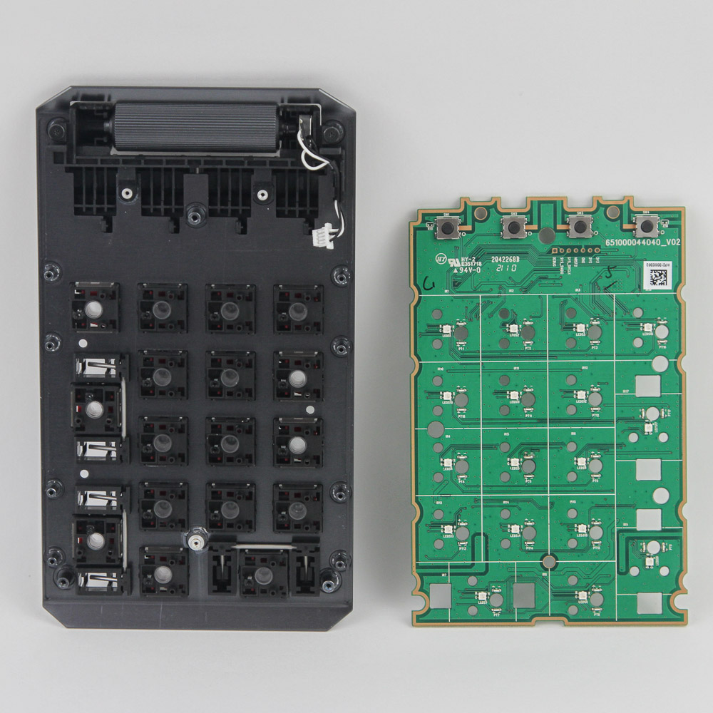
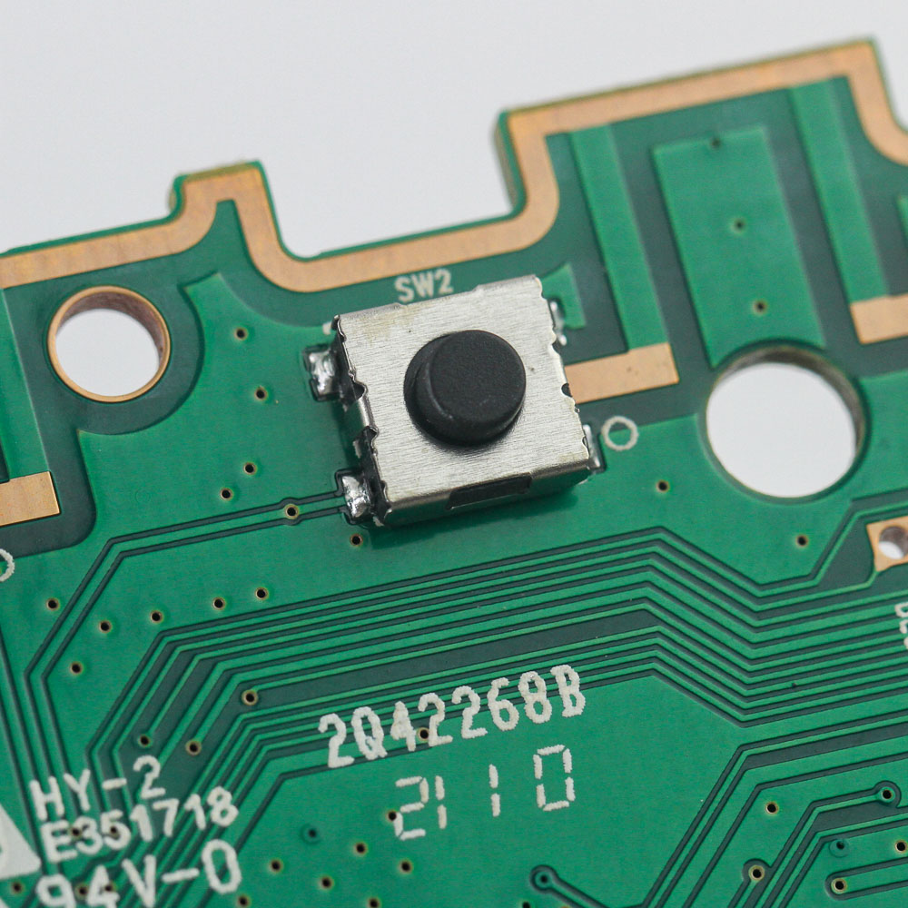
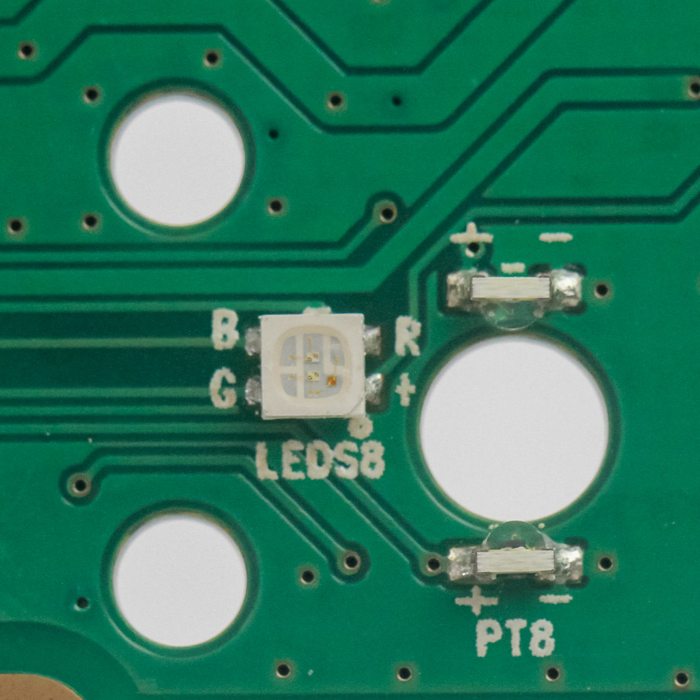
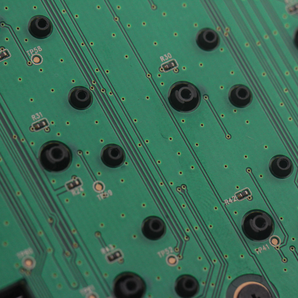
Provided you have disconnected the volume wheel cable too, the PCB can be lifted off completely to expose the other side and the aluminium frame housing the switches. Except for the four buttons that make up the additional keys above the numpad, there is not much to see on the front of the PCB. These are short tactile buttons without any associated LEDs, which instead go to the optical switches for RGB LEDs capable of 8-bit colors on each channel, and a total of 16.8 M colors. Ah wait, we also see the optical source passing through the two diodes used for the actuation mechanism, with the stem of the switch going down as it travels to interrupt the light, which immediately triggers actuation. Compared to mechanical-only switches, this makes for faster actuation and theoretically no debounce.
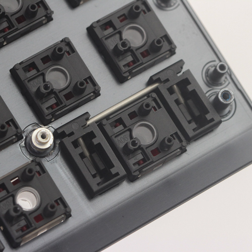
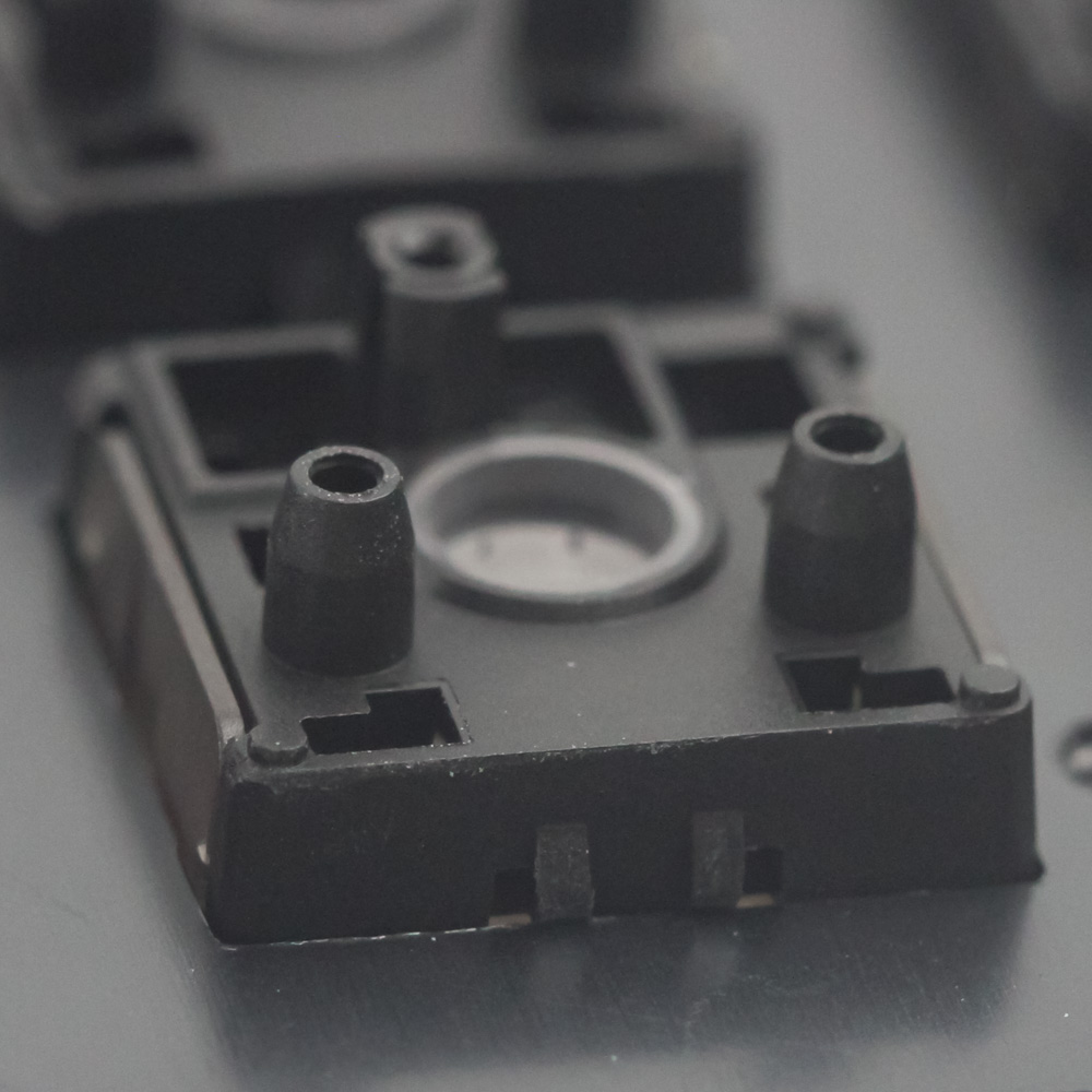
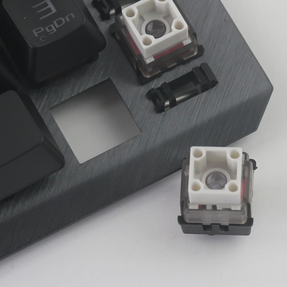
The switches are definitely not soldered to anything, but have retainer clips in the housing push through the cutout in the aluminium frame and hold it in place. This is what makes mechanical hot-swapping from the front difficult. We also get a better look at the stabilizers, should you want to lube them yourself. To remove a switch, and this is the only reason I went this far, push in the retainer clips on one side and then the other. The switch then simply pops out for a closer examination.
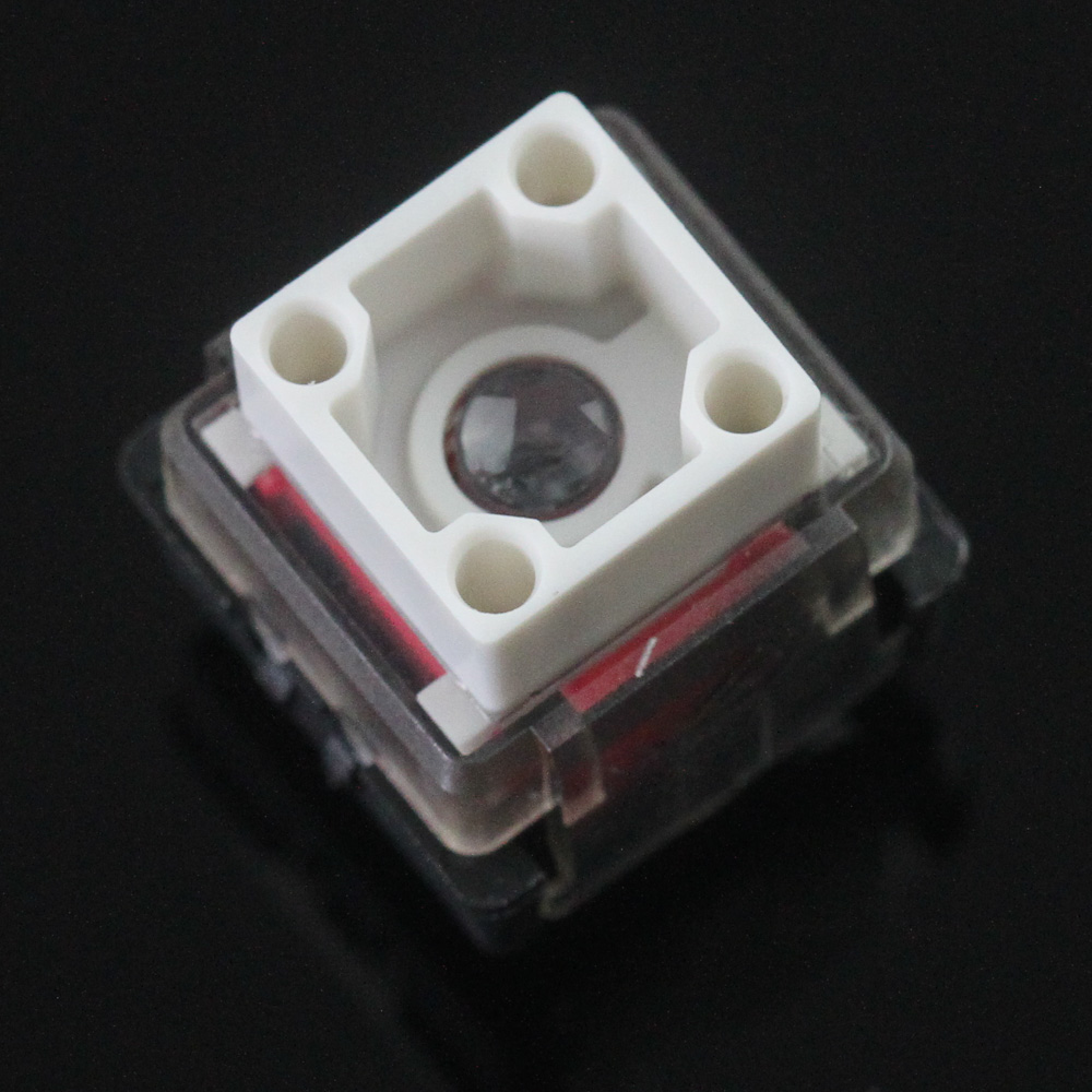
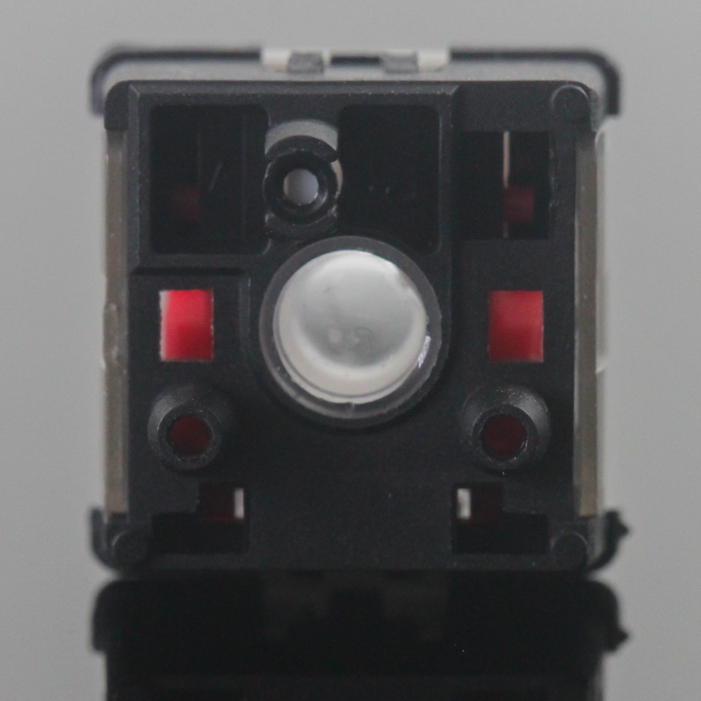
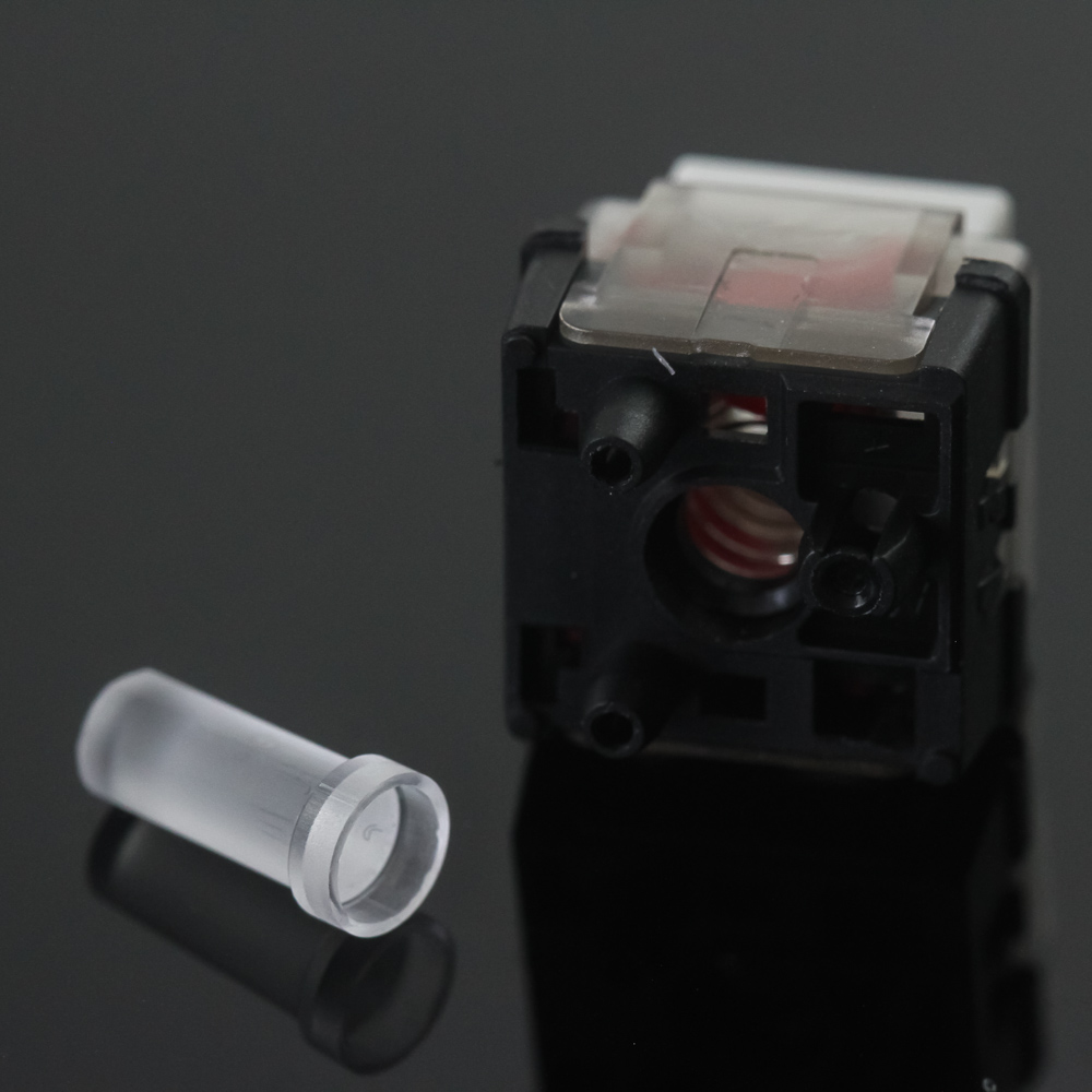
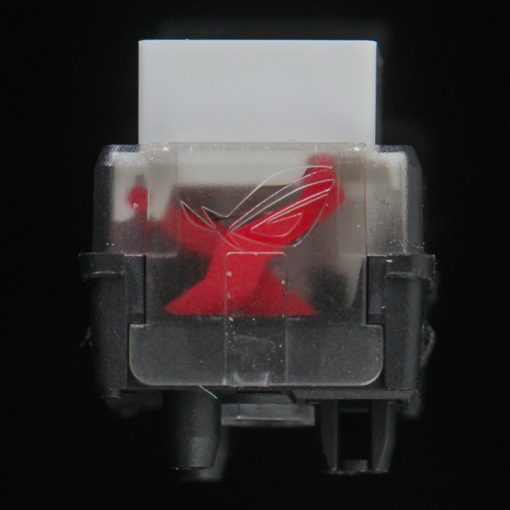
This is definitely the most work I have had to put into taking an optical switch out of a keyboard, but I did it because so many things are different with the ROG RX switches. We saw before how the design allows for central lighting rather than north-facing LEDs shining light through a cutout, as well as openings in the corners the keycap fits into for what should be a more stable typing experience with minimal keycap wobble. A look from the back and sides confirms that this is indeed a switch with three pins, which combine with the clips from earlier to provide a lot of stability to the switch. The light pillar is removed easily enough too, and it diffuses the light shed by the LED for a more uniform and less harsh effect. A look from the side shows the ROG logo on the translucent top, but also teases the innards of the switch, which we will get to on the next page.
Jul 3rd, 2025 22:01 CDT
change timezone
Latest GPU Drivers
New Forum Posts
- GPU-Z Display Bug via DP 2.1? (5)
- [GPU-Z Test Build] New Kernel Driver, Everyone: Please Test (35)
- What Windows is overall the best to you and why? (269)
- How do you view TPU & the internet in general? (With poll) (58)
- HP Zbook 15 G2 GPU Upgrade (12)
- Will you buy a RTX 5090? (610)
- What phone you use as your daily driver? And, a discussion of them. (1756)
- What would you buy? (51)
- A Final Fantasy IX Reminiscence - My love letter and homage to one of the best stories ever told (90)
- GravityMark v1.89 GPU Benchmark (309)
Popular Reviews
- ASUS ROG Crosshair X870E Extreme Review
- Crucial T710 2 TB Review - Record-Breaking Gen 5
- Fractal Design Scape Review - Debut Done Right
- PowerColor ALPHYN AM10 Review
- Sapphire Radeon RX 9060 XT Pulse OC 16 GB Review - An Excellent Choice
- Upcoming Hardware Launches 2025 (Updated May 2025)
- AMD Ryzen 7 9800X3D Review - The Best Gaming Processor
- Sapphire Radeon RX 9070 XT Nitro+ Review - Beating NVIDIA
- SCHENKER KEY 18 Pro (E25) Review - Top-Tier Contender
- AVerMedia CamStream 4K Review
TPU on YouTube
Controversial News Posts
- Intel's Core Ultra 7 265K and 265KF CPUs Dip Below $250 (288)
- NVIDIA Grabs Market Share, AMD Loses Ground, and Intel Disappears in Latest dGPU Update (212)
- Some Intel Nova Lake CPUs Rumored to Challenge AMD's 3D V-Cache in Desktop Gaming (140)
- NVIDIA GeForce RTX 5080 SUPER Could Feature 24 GB Memory, Increased Power Limits (115)
- Microsoft Partners with AMD for Next-gen Xbox Hardware (105)
- NVIDIA Launches GeForce RTX 5050 for Desktops and Laptops, Starts at $249 (105)
- Intel "Nova Lake‑S" Series: Seven SKUs, Up to 52 Cores and 150 W TDP (100)
- NVIDIA DLSS Transformer Cuts VRAM Usage by 20% (97)