 25
25
ASUS ROG Claymore II Review - Three Keyboards in One!
Software »Disassembly: Part 2


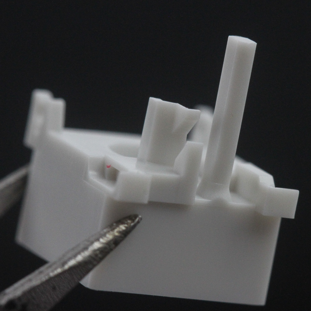
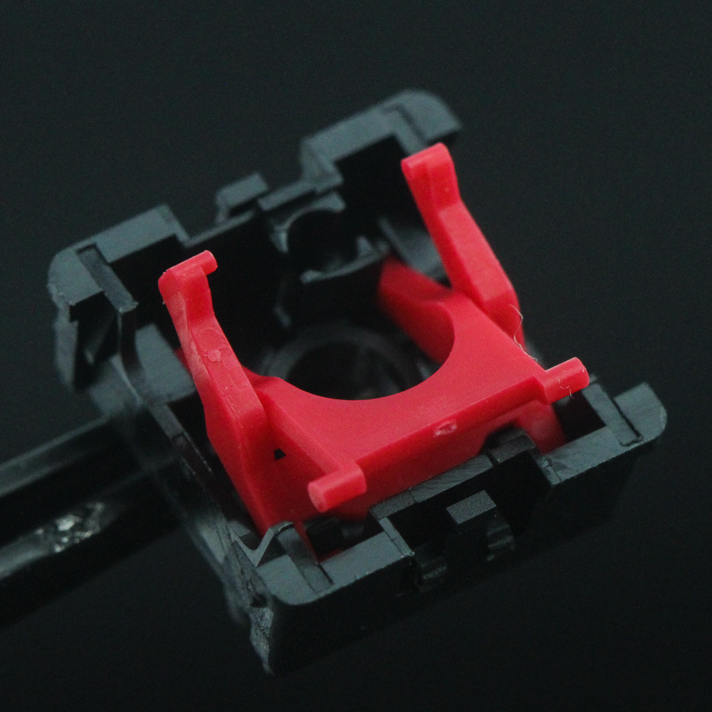
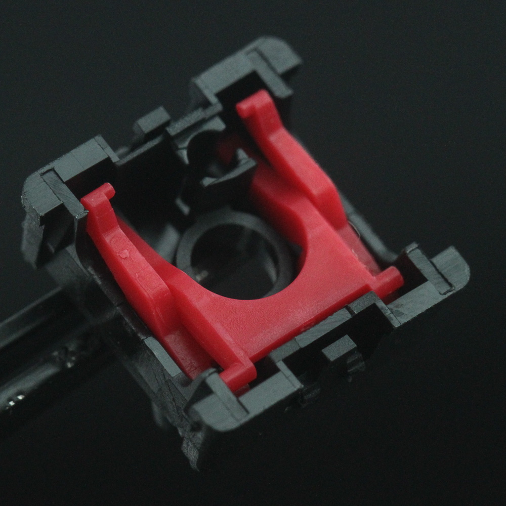
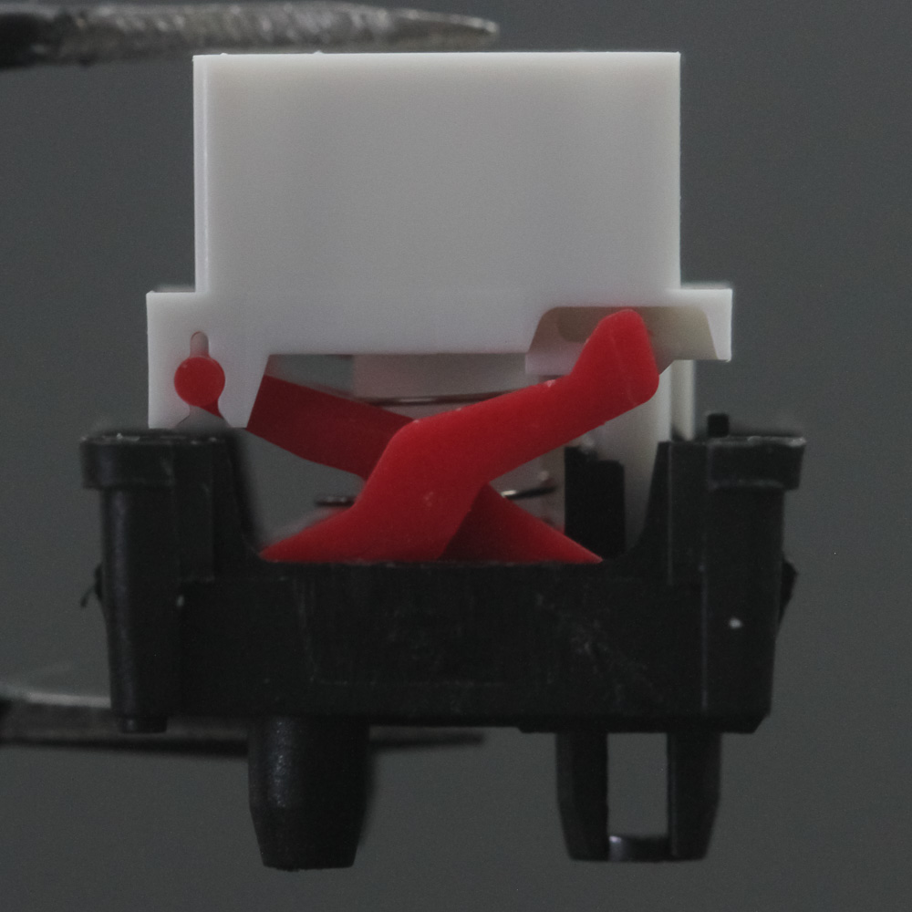
This page basically describes the disassembly of an optical switch keyboard and begins with a look inside one of the switches. Getting to the switch took a while, though, which is why this is the second part of the disassembly coverage with the ROG Claymore II. Once you have the switch in your hands, taking it apart is quite simple—just separate the interlocking tabs keeping the translucent top in place over the black housing. Note also that the stem clips into place on the red (or blue, if you have the ROG RX Blue switches) stabilizers, so carefully separate it. The spring just pops out, so keep an eye on that roller, too. The best way I can describe the ROG RX Red is as an Omron mechanical switch that loved a scissor switch very much and decided to turn to the light. Elements from many different switches have been put together and refined here. Take the stem, which is square to mate nicely with the top and clips onto the scissor-style stabilizers. The long finger in the stem is what eventually interrupts the light signal of the two diodes on each switch, which in turn triggers keystroke actuation. The X/scissor-style stabilizers slide up and down the housing and are part of the mechanical facet of this optical-mechanical switch.
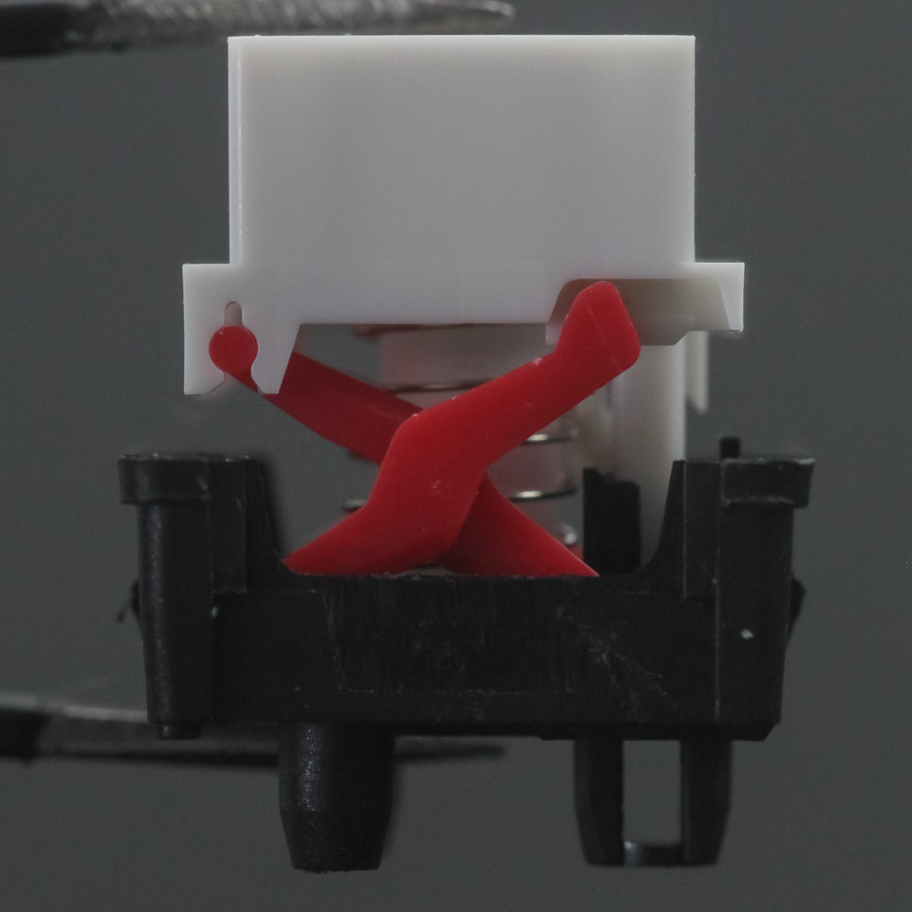
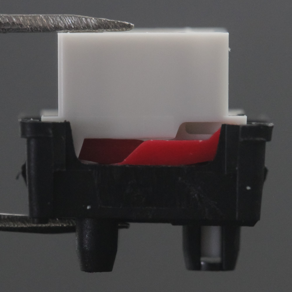
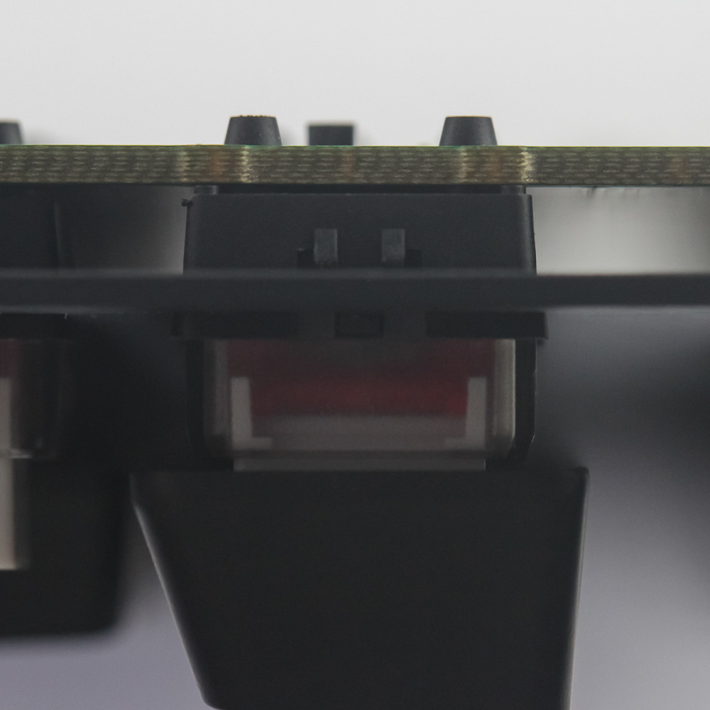
With the top removed and looking in from the side, we get a closer look at the switch-travel mechanism. As the stem goes down, the stabilizers glide through a cutout on either side, with the spring providing the travel resistance. This means the gliding action will make or break the switches, and some lube would have helped with a couple of the switches I had. The vast majority were quite smooth though, so take that for what you will. The two side pins in the black housing are only for stability on the PCB, with the third pin having a cutout for the actuation mechanism, and the stem finger to slide into.
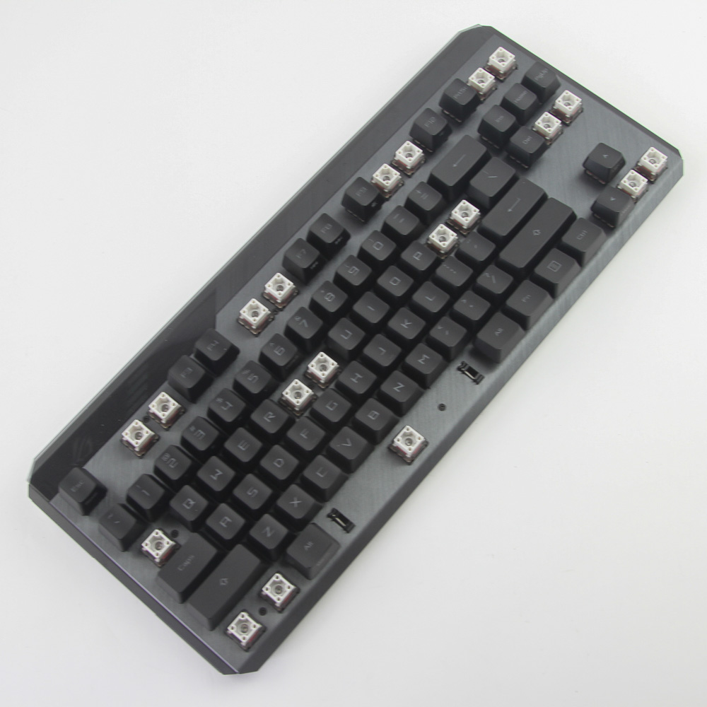
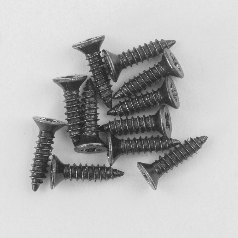
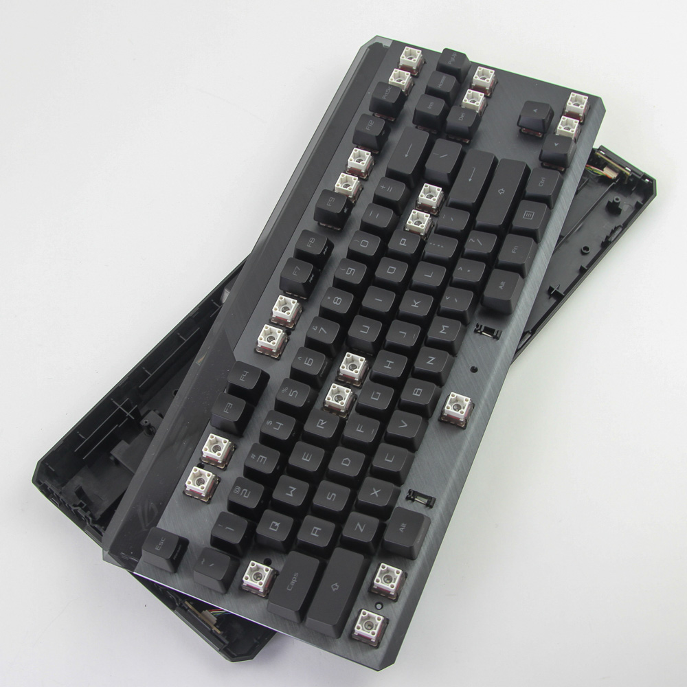
Now on to the TKL unit of the ROG Claymore II itself, which will be a much simpler affair as I am only interested in what makes it tick now that we have already examined the switches. There are no hidden screws on the back this time. We instead have 11 Phillips head screws that are accessible after removing specific keycaps as seen above. Once done, the aluminium frame can be lifted off, but not completely separated.
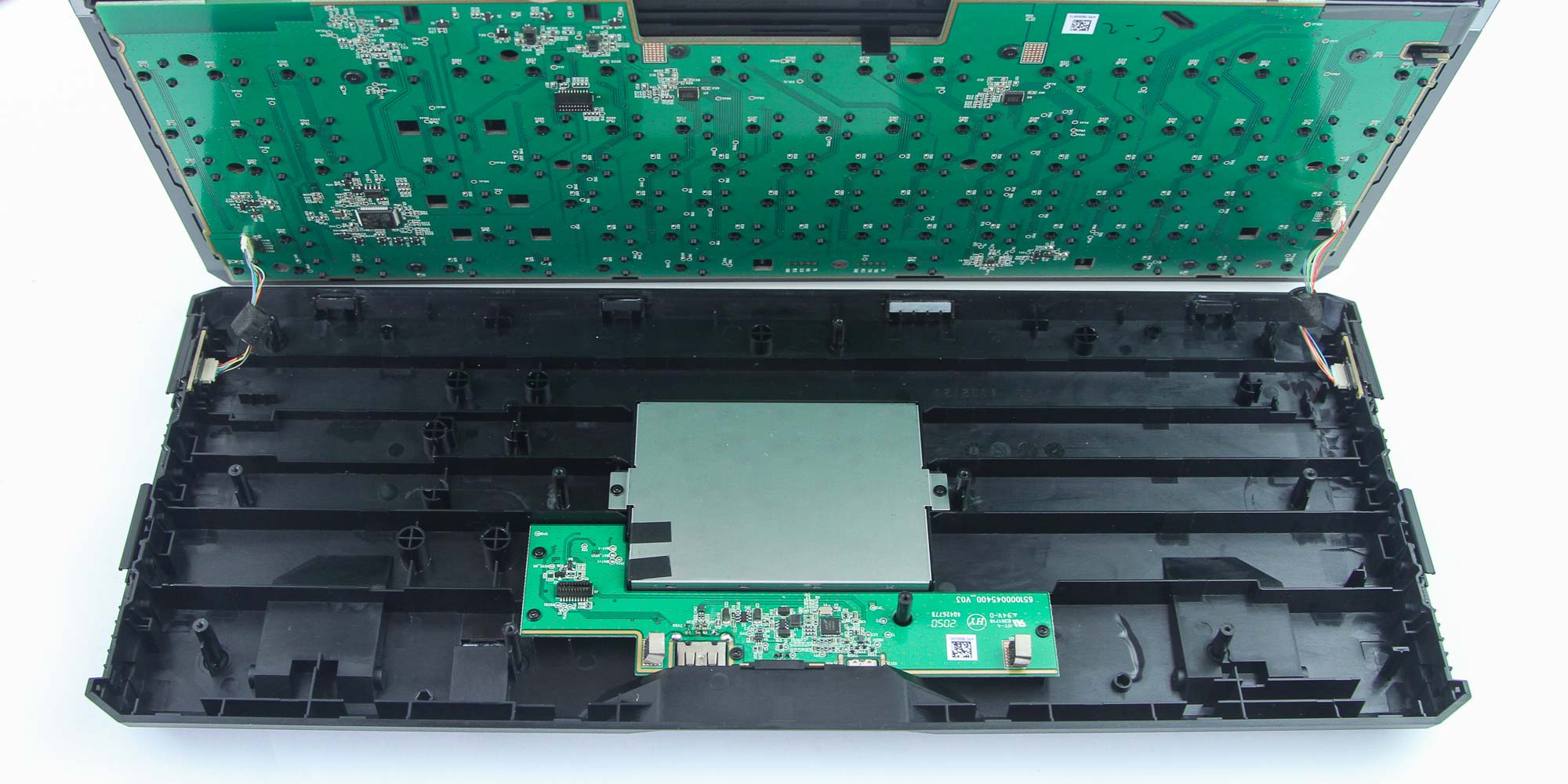
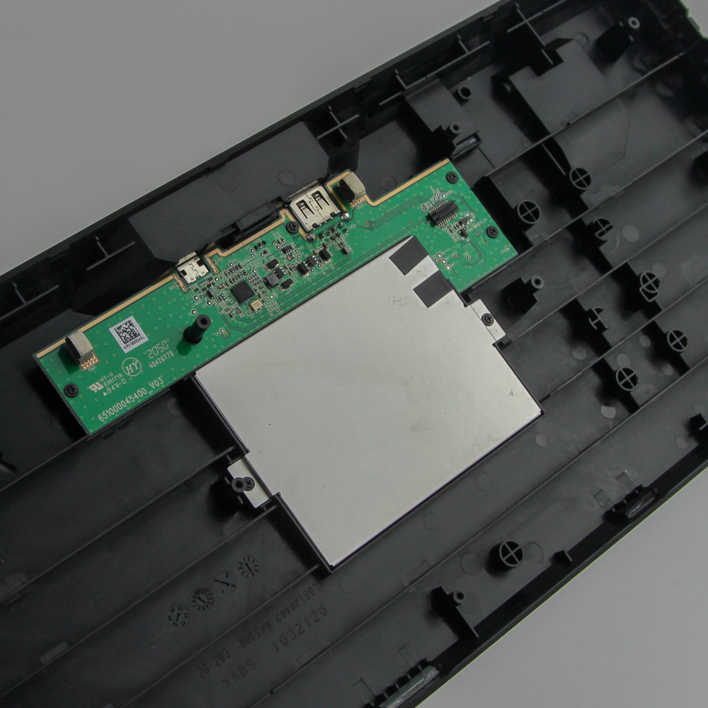
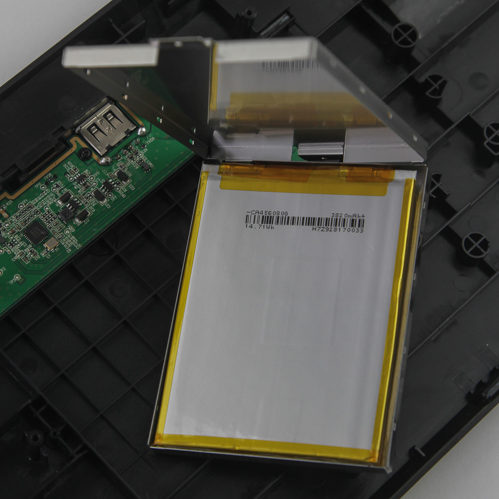
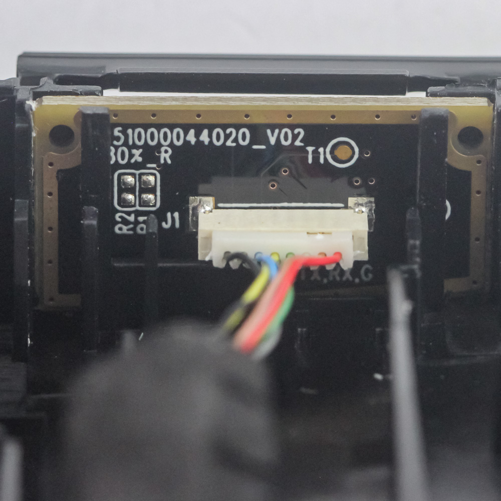
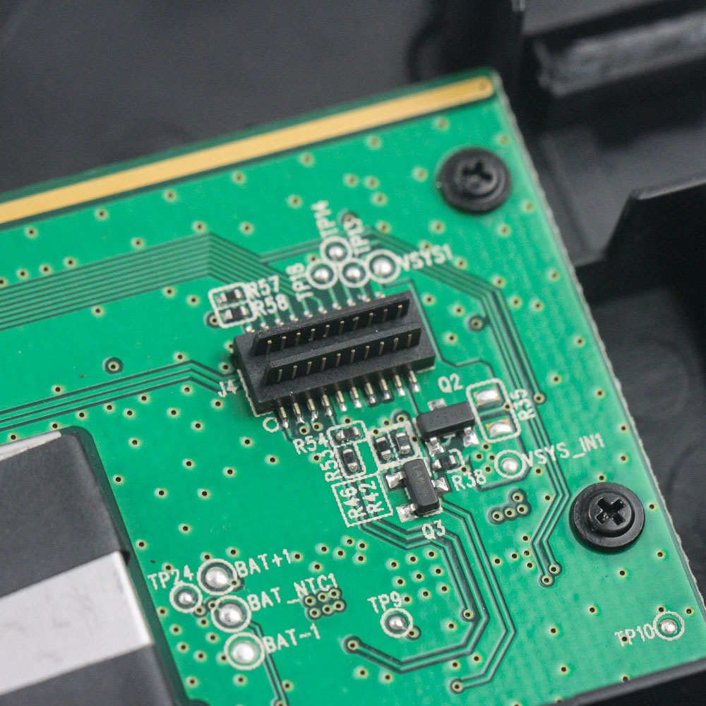
As expected, two short cables on the side go to the PCB for the hot-swappable numpad. I suppose in the absence of hot-swappable switches, having the same with the numpad will do! Interestingly, there are no other cables to worry about. So how does the keyboard get power in wireless mode? Let's take a closer look at the bottom case panel to find out, which we can now indeed confirm is made out of ABS plastic. There is a metal-shielded compartment with the top screwed in place on either side, and lifting it off reveals the 3820 mAh battery inside. ASUS rates the battery at 4000 mAh, which is close enough, at least practically. A wire goes from the battery to the daughter PCB with the wired I/O section on the bottom panel. So now we have to figure out where the internal USB connection from this daughter PCB is taken to the primary one, along with the battery power itself. A connector jutting out vertically on the daughter PCB sheds some light on this.
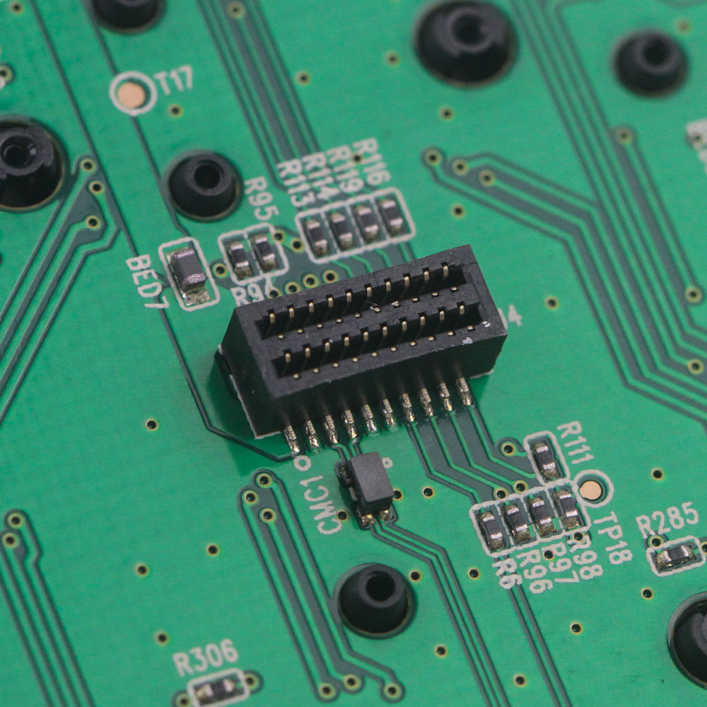
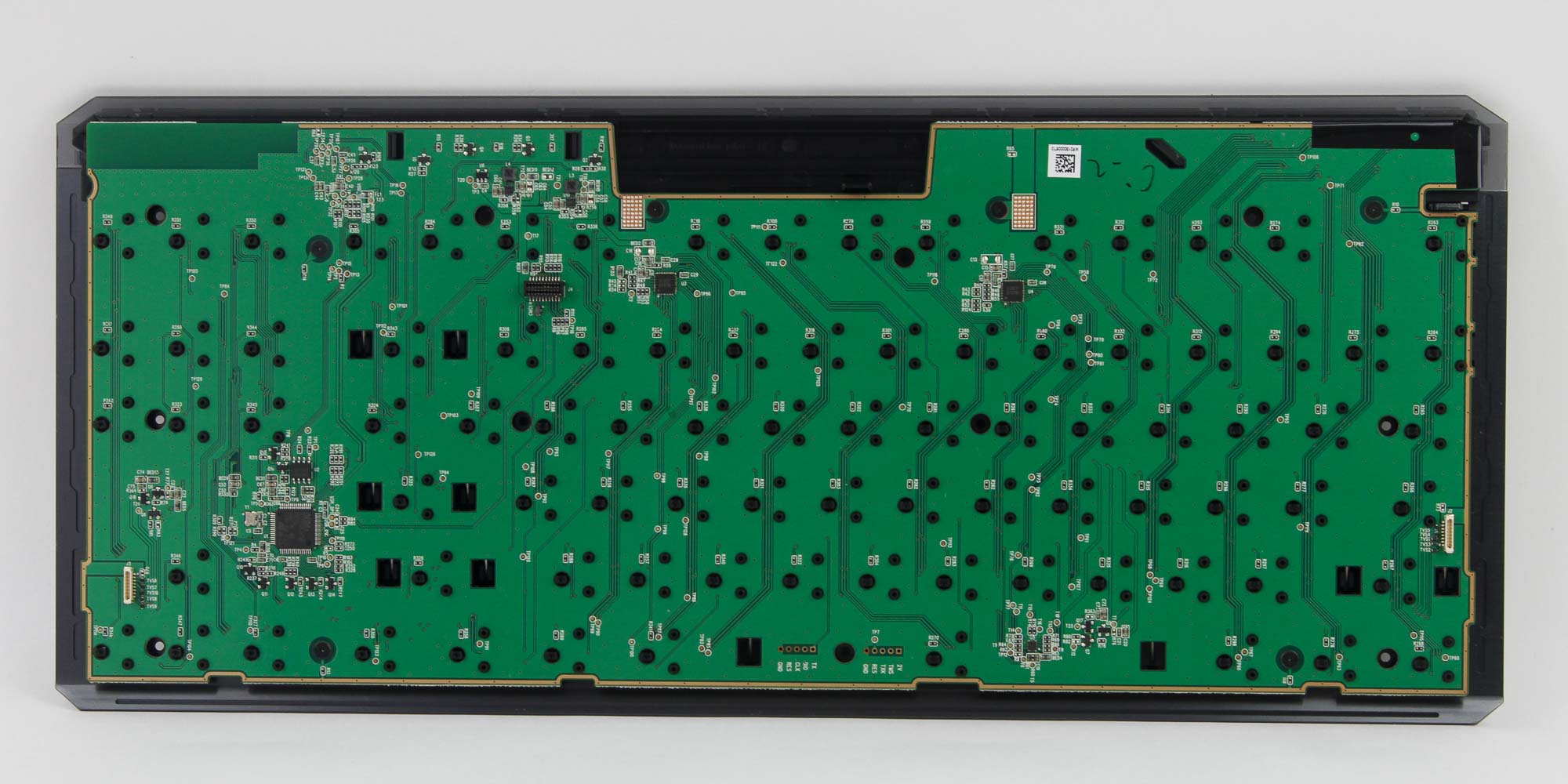
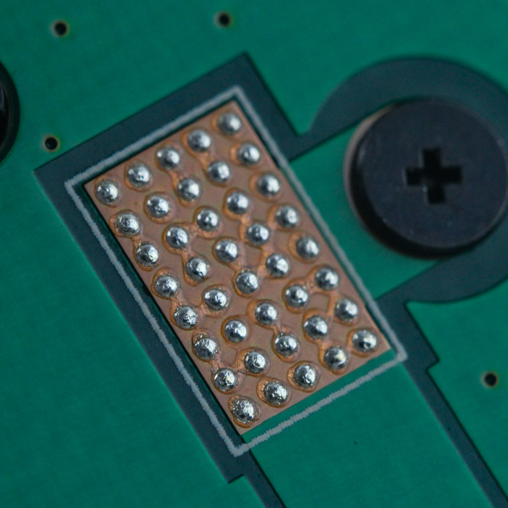
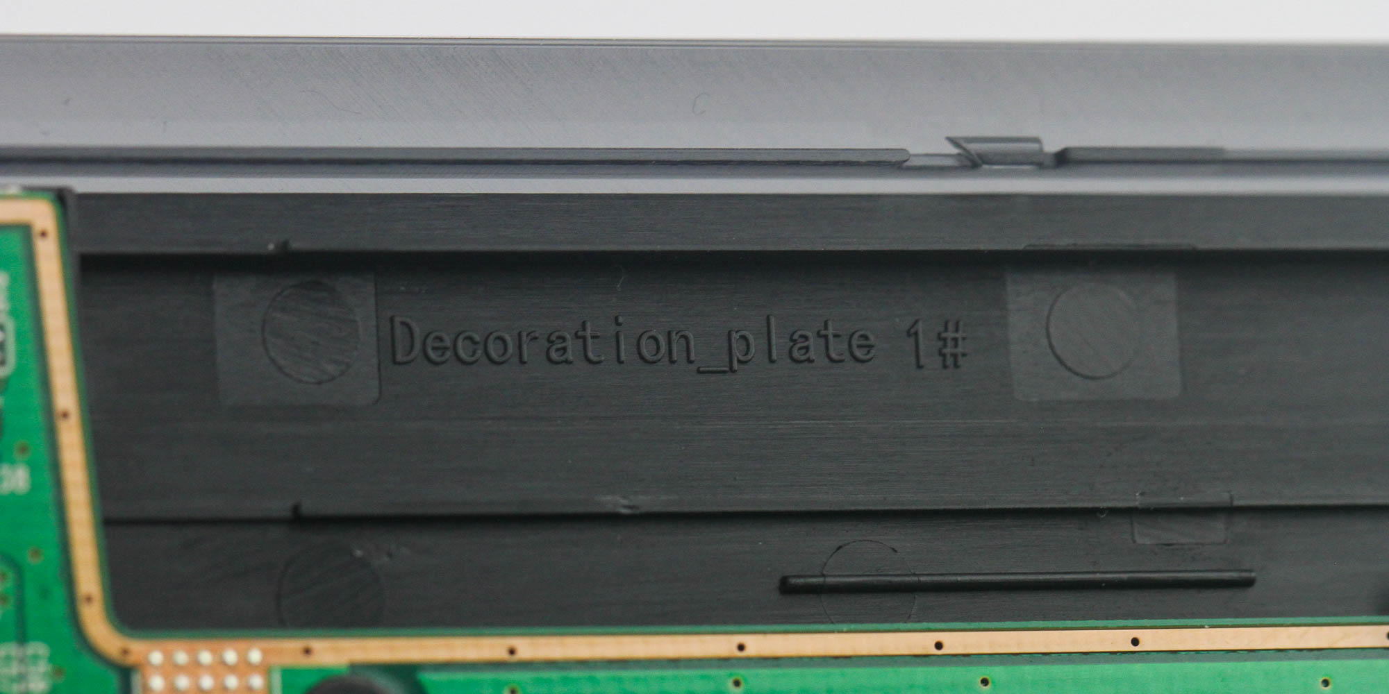
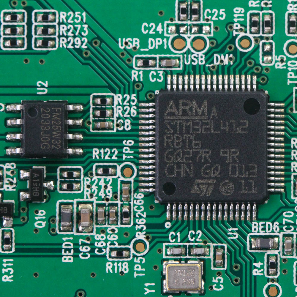
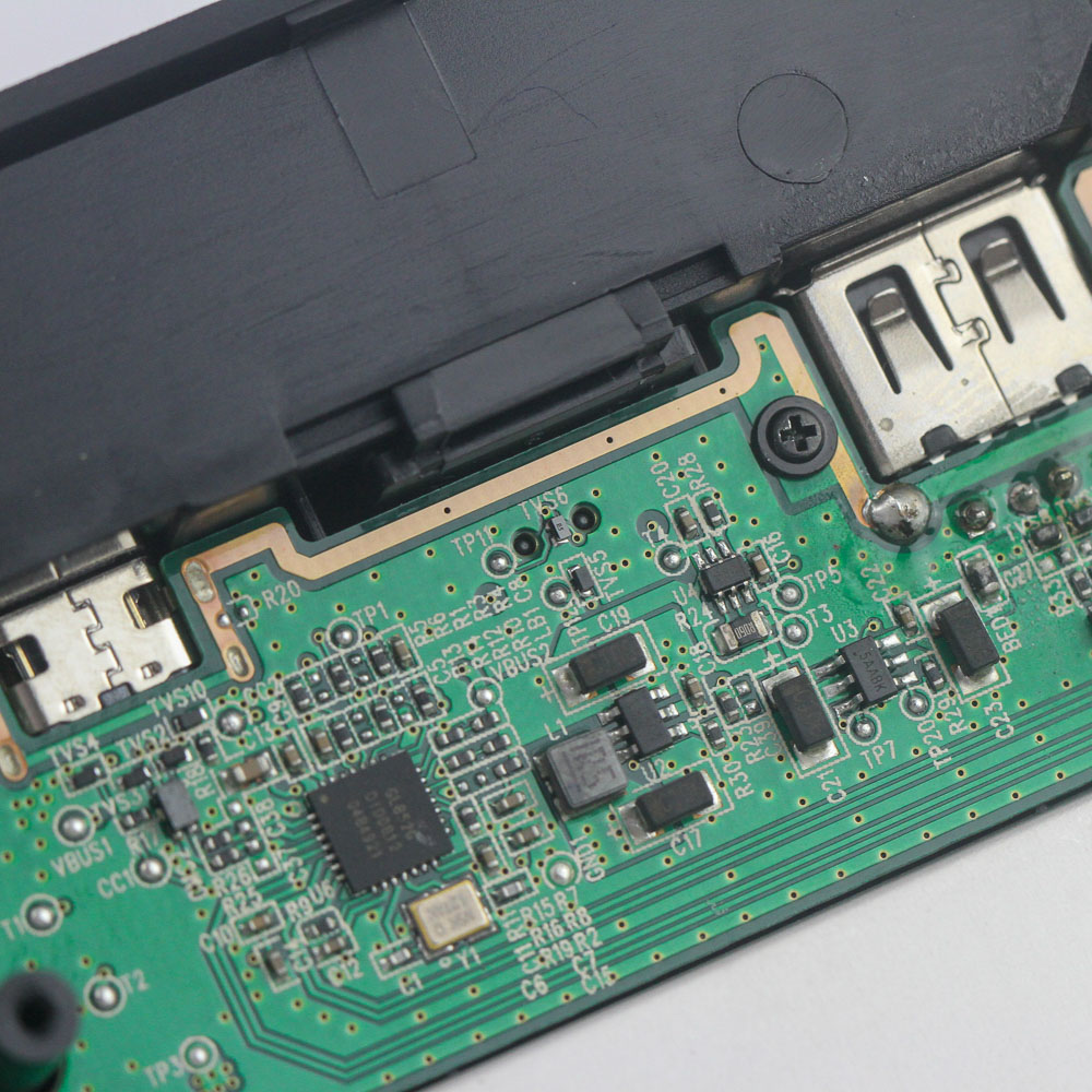
Ah, and the mating connector on the primary PCB solves that problem. These two get around the need for separate wires and help keep things tidy inside. The primary PCB, also green, is basically a larger version of the smaller one used for the numpad. There is not much soldering here, either, with the switches just slotted in place in the aluminium frame, and there is even a spare bare pad. It is also funny to see the plastic trim referred to as a decoration plate. Powering the TKL keyboard unit is a similar STMicroelectronics STM32L412R8 Arm Cortex-M4 microcontroller with 64 KB of onboard flash memory for all the pre-programmed functions. As expected, the PCB has multiple layers, and the side view also better reveals the thickness of the aluminium frame itself.
Before we move on, be advised that disassembly may void the warranty and that TechPowerUp is not liable for any damages incurred if you decide to go ahead and do so anyway.
Jul 13th, 2025 02:51 CDT
change timezone
Latest GPU Drivers
New Forum Posts
- 9070XT BIOS flash (what to use?) (6)
- New ToS of Take Two and 2K (12)
- Radeon RX 6700, 6700 XT & 6750 XT users club (1138)
- 6400c30 vs 8000c36 Ryzen 9800X3D (0)
- Best motherboards for XP gaming (116)
- 9800x3D - 6400 CL32 1:1 not stable (12)
- Is there a WIFI chip I should get? (1)
- What are you playing? (23945)
- 9060 XT 16GB or 6800 XT/6900XT? (30)
- ASUS ProArt GeForce RTX 4060 Ti OC Edition 16GB GDDR6 Gaming - nvflash64 VBIOS mismatch (5)
Popular Reviews
- Fractal Design Epoch RGB TG Review
- Lexar NM1090 Pro 4 TB Review
- Corsair FRAME 5000D RS Review
- Our Visit to the Hunter Super Computer
- NVIDIA GeForce RTX 5050 8 GB Review
- NZXT N9 X870E Review
- Sapphire Radeon RX 9060 XT Pulse OC 16 GB Review - An Excellent Choice
- AMD Ryzen 7 9800X3D Review - The Best Gaming Processor
- Upcoming Hardware Launches 2025 (Updated May 2025)
- Chieftec Iceberg 360 Review
TPU on YouTube
Controversial News Posts
- Intel's Core Ultra 7 265K and 265KF CPUs Dip Below $250 (288)
- Some Intel Nova Lake CPUs Rumored to Challenge AMD's 3D V-Cache in Desktop Gaming (140)
- AMD Radeon RX 9070 XT Gains 9% Performance at 1440p with Latest Driver, Beats RTX 5070 Ti (131)
- NVIDIA Launches GeForce RTX 5050 for Desktops and Laptops, Starts at $249 (120)
- NVIDIA GeForce RTX 5080 SUPER Could Feature 24 GB Memory, Increased Power Limits (115)
- Microsoft Partners with AMD for Next-gen Xbox Hardware (105)
- Intel "Nova Lake‑S" Series: Seven SKUs, Up to 52 Cores and 150 W TDP (100)
- NVIDIA DLSS Transformer Cuts VRAM Usage by 20% (97)