 0
0
LEPA G850-MAS 850 W Review
Ripple Measurements »Advanced Transient Response Tests
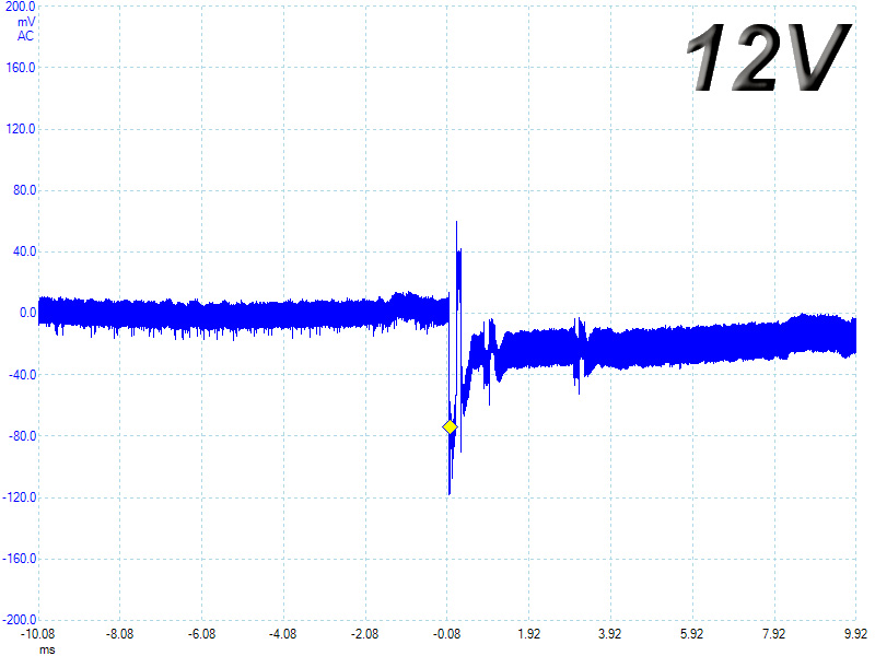
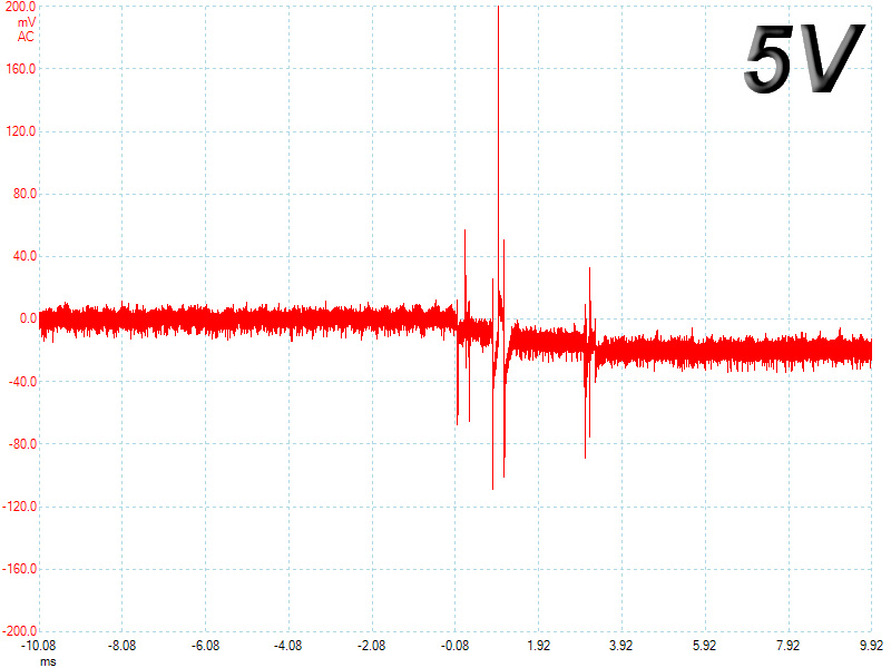
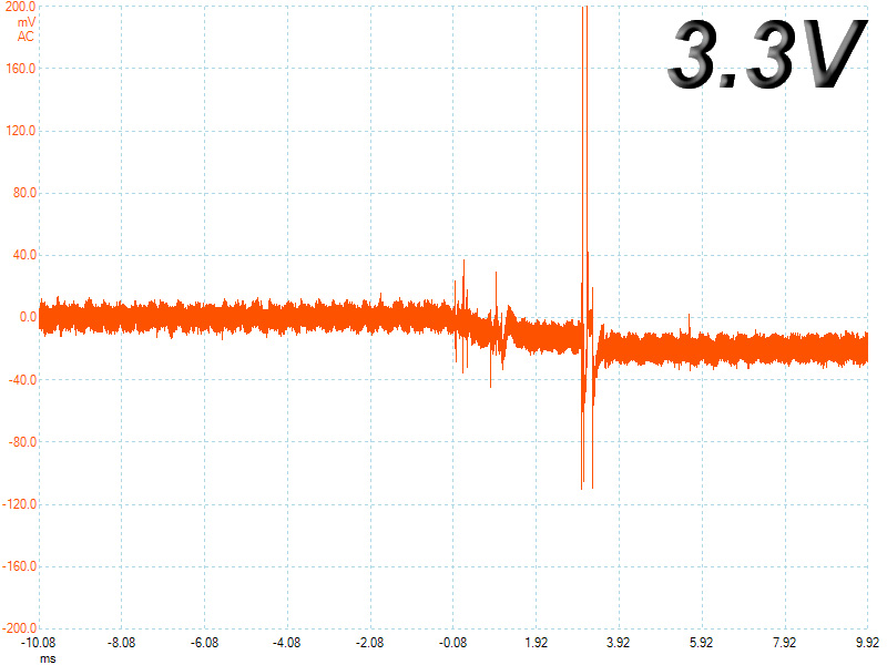
In these tests, we monitor the response of the PSU in two different scenarios. First, a transient load (11 A at +12V, 5 A at 5V, 6 A at 3.3V, and 0.5 A at 5VSB) is applied to the PSU for 50 ms, while the latter is working at a 20% load state. In the second scenario, the PSU, while working at 50% load, is hit by the same transient load. In both tests, we measure the voltage drops that the transient load causes using our oscilloscope. The voltages should in any case remain within the regulation limits defined by the ATX specification. We must stress here that the above tests are crucial since they simulate transient loads that a PSU is very likely to handle (e.g., booting a RAID array, an instant 100% load of CPU/VGAs, etc.) We call these tests "Advanced Transient Response Tests" and they are designed to be very tough to master, especially for PSUs with capacities lower than 500 W.| Advanced Transient Response 20% | ||||
|---|---|---|---|---|
| Voltage | Before | After | Change | Pass/Fail |
| 12 V | 12.177V | 12.053V | 1.02% | Pass |
| 5 V | 5.100V | 4.994V | 2.08% | Pass |
| 3.3 V | 3.321V | 3.211V | 3.31% | Pass |
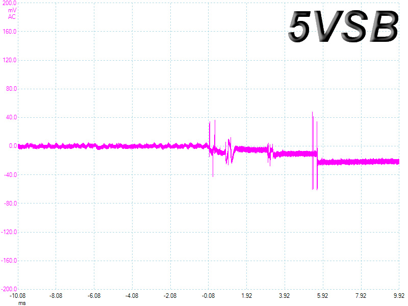
| 5VSB | 5.073V | 5.005V | 1.34% | Pass |
| Advanced Transient Response 50% | ||||
|---|---|---|---|---|
| Voltage | Before | After | Change | Pass/Fail |
| 12 V | 12.106V | 11.988V | 0.97% | Pass |
| 5 V | 5.056V | 4.947V | 2.16% | Pass |
| 3.3 V | 3.270V | 3.160V | 3.36% | Pass |
| 5VSB | 5.056V | 4.995V | 1.21% | Pass |
In general, all deviations are small, especially at +12V, which is the most important rail. However, the low initial voltage of the 3.3V rail has as an effect with a low voltage reading on the second test; one that is close to the lower limit ATX spec sets for this rail (3.14V). All other rails register voltages close to the nominal values during the application of the transient load.
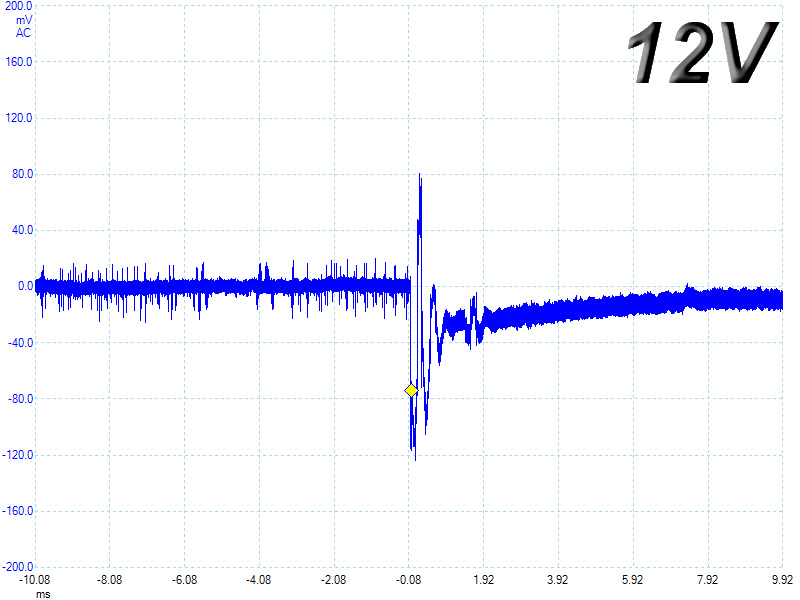
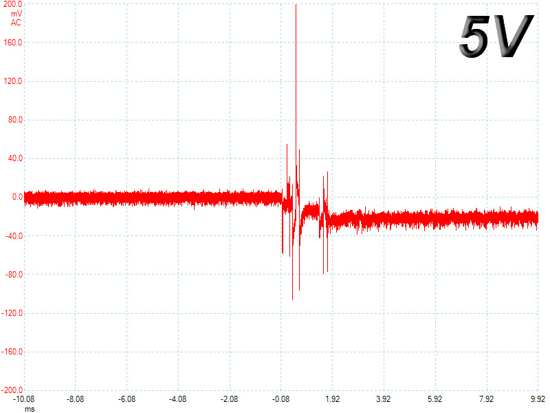
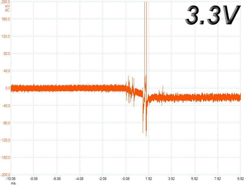
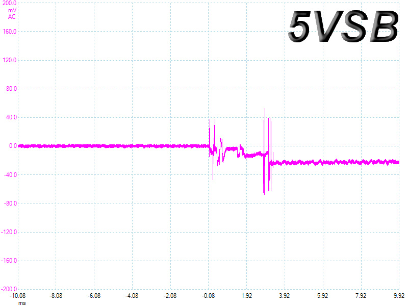
Below, you will see the oscilloscope screenshots that we took during the Advanced Transient Response Testing.
Transient Response at 20% Load
Transient Response at 50% Load
Turn-On Transient Tests
In the next set of tests, we measure the response of the PSU in simpler scenarios of transient loads, during the power-on phase of the PSU. In the first test, we turn off the PSU, dial 2 A of load at 5VSB and then switch on the PSU. In the second test, while the PSU is in standby mode, we dial the maximum load that +12V can handle and start the PSU. In the last test, while the PSU is completely switched off (we cut off power or switch off the PSU's on/off switch), we dial the maximum load that the +12V rail can handle, switch the PSU on from the loader, and restore power. The ATX specification states that recorded spikes on all rails should not exceed 10% of their nominal values (e.g., +10% for 12V is 13.2V and for 5V is 5.5V).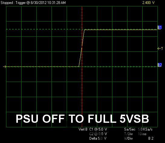
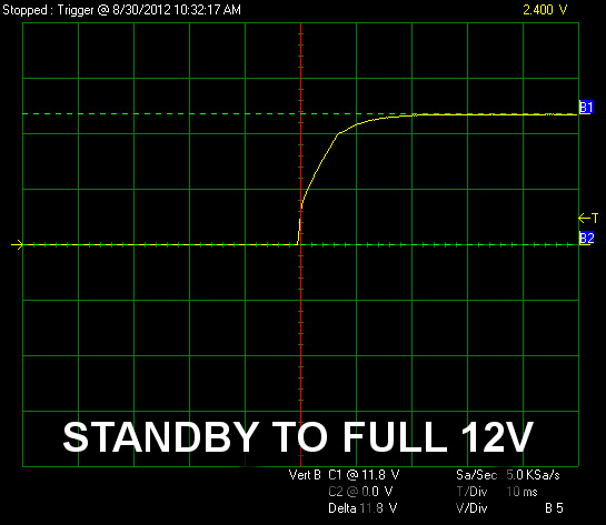
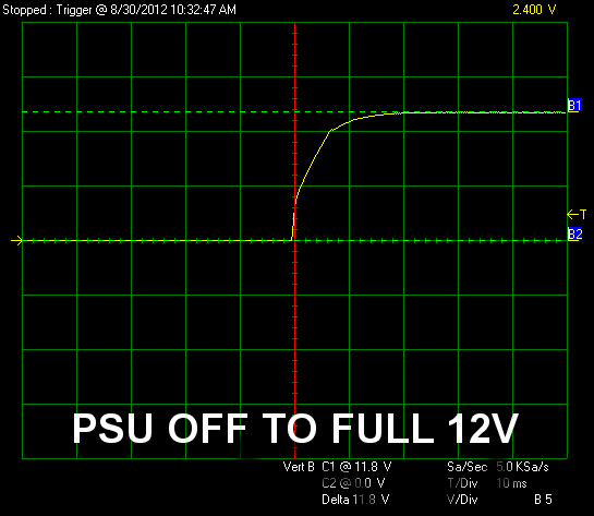
The PSU registered impeccable performance here with smooth slopes and a rise time always within the specified ATX standard range (0.2-20ms).
Jul 13th, 2025 02:59 CDT
change timezone
Latest GPU Drivers
New Forum Posts
- Best motherboards for XP gaming (117)
- 9800x3D - 6400 CL32 1:1 not stable (13)
- Archival HDD constantly starting up for no reason (0)
- 6400c30 vs 8000c36 Ryzen 9800X3D (1)
- 9070XT BIOS flash (what to use?) (6)
- New ToS of Take Two and 2K (12)
- Radeon RX 6700, 6700 XT & 6750 XT users club (1138)
- Is there a WIFI chip I should get? (1)
- What are you playing? (23945)
- 9060 XT 16GB or 6800 XT/6900XT? (30)
Popular Reviews
- Fractal Design Epoch RGB TG Review
- Lexar NM1090 Pro 4 TB Review
- Corsair FRAME 5000D RS Review
- Our Visit to the Hunter Super Computer
- NVIDIA GeForce RTX 5050 8 GB Review
- NZXT N9 X870E Review
- Sapphire Radeon RX 9060 XT Pulse OC 16 GB Review - An Excellent Choice
- AMD Ryzen 7 9800X3D Review - The Best Gaming Processor
- Upcoming Hardware Launches 2025 (Updated May 2025)
- Chieftec Iceberg 360 Review
TPU on YouTube
Controversial News Posts
- Intel's Core Ultra 7 265K and 265KF CPUs Dip Below $250 (288)
- Some Intel Nova Lake CPUs Rumored to Challenge AMD's 3D V-Cache in Desktop Gaming (140)
- AMD Radeon RX 9070 XT Gains 9% Performance at 1440p with Latest Driver, Beats RTX 5070 Ti (131)
- NVIDIA Launches GeForce RTX 5050 for Desktops and Laptops, Starts at $249 (120)
- NVIDIA GeForce RTX 5080 SUPER Could Feature 24 GB Memory, Increased Power Limits (115)
- Microsoft Partners with AMD for Next-gen Xbox Hardware (105)
- Intel "Nova Lake‑S" Series: Seven SKUs, Up to 52 Cores and 150 W TDP (100)
- NVIDIA DLSS Transformer Cuts VRAM Usage by 20% (97)