 0
0
Antec High Current Gamer Modular 750 W Review
Ripple Measurements »Advanced Transient Response Tests
In these tests, we monitor the response of the PSU in two different scenarios. First, a transient load (10 A at +12V, 5 A at 5V, 5 A at 3.3V, and 0.5 A at 5VSB) is applied to the PSU for 200 ms while the latter is working at a 20% load state. In the second scenario, the PSU, while working at 50% load, is hit by the same transient load. In both tests, we measure the voltage drops that the transient load causes using our oscilloscope. The voltages should remain within the regulation limits defined by the ATX specification. We must stress here that the above tests are crucial since they simulate transient loads that a PSU is very likely to handle (e.g., booting a RAID array, an instant 100% load of CPU/VGAs, etc.). We call these tests "Advanced Transient Response Tests", and they are designed to be very tough to master, especially for PSUs with capacities below 500 W.| Advanced Transient Response 20% | ||||
|---|---|---|---|---|
| Voltage | Before | After | Change | Pass/Fail |
| 12 V | 12.203V | 12.100V | 0.84% | Pass |
| 5 V | 5.082V | 5.002V | 1.57% | Pass |
| 3.3 V | 3.358V | 3.246V | 3.34% | Pass |
| 5VSB | 5.088V | 5.055V | 0.65% | Pass |
| Advanced Transient Response 50% | ||||
|---|---|---|---|---|
| Voltage | Before | After | Change | Pass/Fail |
| 12 V | 12.167V | 12.085V | 0.67% | Pass |
| 5 V | 5.055V | 4.980V | 1.48% | Pass |
| 3.3 V | 3.332V | 3.204V | 3.84% | Pass |
| 5VSB | 5.053V | 5.012V | 0.81% | Pass |
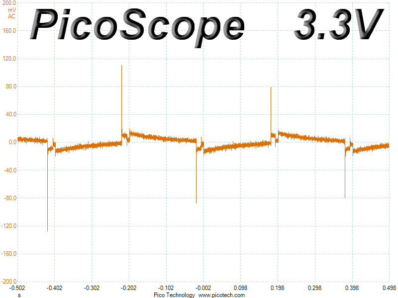
The deviation of all rails was relative small in the above tests. Only the 3.3V rail registered a deviation above 3% on both tests--voltage drops were thus well controlled. The +12V rail, the most significant of all rails, exhibited very good performance by registering a deviation below 1% on both tests.
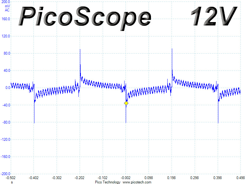
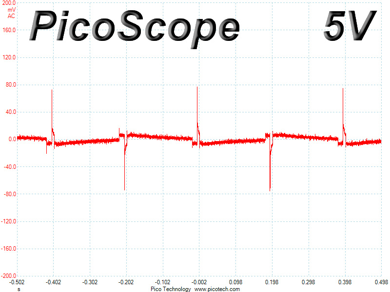
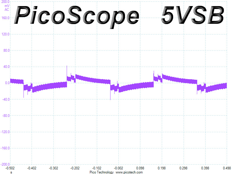
Below, you will find the oscilloscope screenshots that we took during Advanced Transient Response Testing.
Transient Response at 20% Load
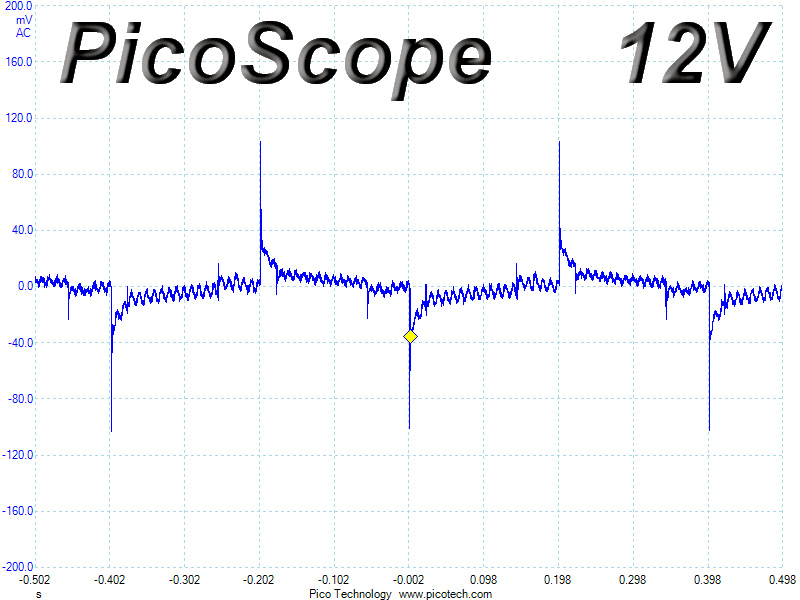
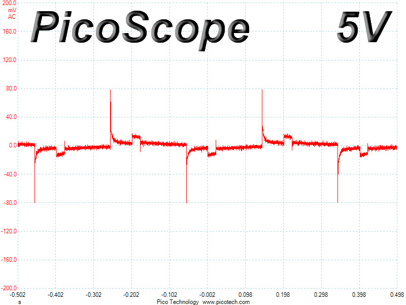
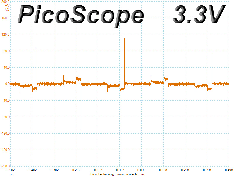
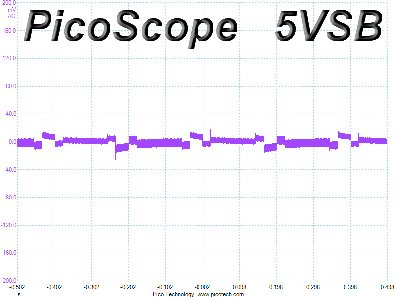
Transient Response at 50% Load
Turn-On Transient Tests
We measure the response of the PSU in simpler scenarios of transient loads--during the power-on phase of the PSU--in the next set of tests. In the first test, we turn the PSU off, dial the maximum current that the 5VSB can output, and then switch on the PSU. In the second test, we dial the maximum load +12V can handle and start the PSU while the PSU is in standby mode. In the last test, while the PSU is completely switched off (we cut off power or switch off the PSU's on/off switch), we dial the maximum load that the +12V rail can handle before switching the PSU on from the loader and restoring power. The ATX specification states that recorded spikes on all rails should not exceed 10% of their nominal values (e.g., +10% for 12V is 13.2V and 5.5V for 5V).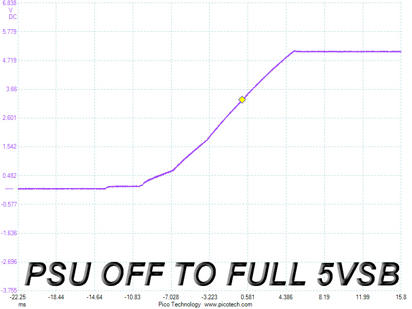
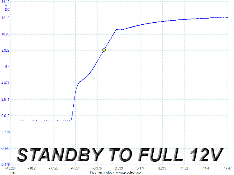
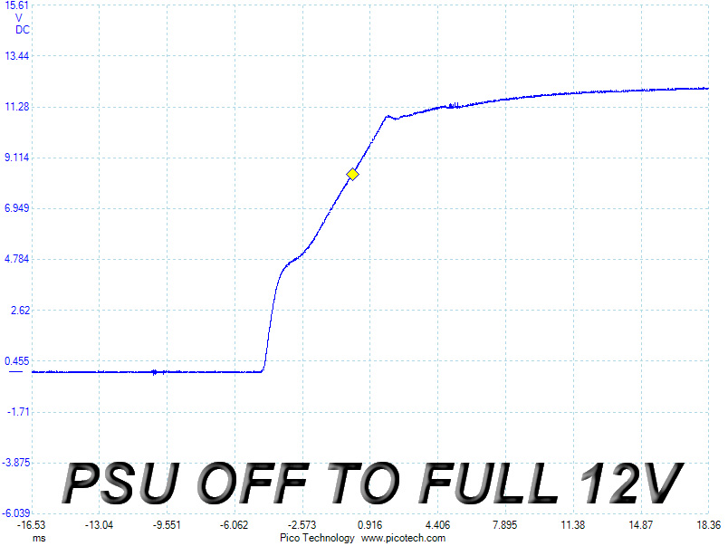
We noticed a tiny voltage overshoot on the 5VSB rail. Spikes in the other two tests were a little larger but still small and far below the limit. General performance on these tests was good enough and would even be better if the slopes of the +12V rail ramped up smoothly on both tests.
Dec 29th, 2024 12:56 EST
change timezone
Latest GPU Drivers
New Forum Posts
- Mechanical keyboards that don't just die..? (18)
- Gaming build advice (7)
- 4 pin AIO MB connector for fan AND speed control? (19)
- Issues with a Sapphire Pulse RX 580 8GB (6)
- Overclocking My System Advice for CPU, RAM, and GPU (18)
- Upgrade advice please (42)
- Next Gen GPU's will be even more expensive (538)
- Profile switching automatically (1)
- What are you playing? (22476)
- Free Games Thread (4342)
Popular Reviews
- Zotac Zone Review - Amazing Screen and Great Gaming Performance
- GPU Test System Update for 2025
- Quick Look: Cooler Master MasterFrame 600
- Arbiter Studio AKITSU Review
- Arrow Lake Retested with Latest 24H2 Updates and 0x114 Microcode
- KiiBOOM Loop75 Wireless Mechanical Keyboard Review
- AMD Ryzen 7 9800X3D Review - The Best Gaming Processor
- Intel Arc B580 Review - Excellent Value
- Upcoming Hardware Launches 2024 (Updated Nov 2024)
- EIZO FlexScan EV3240X Review - It Means Business
Controversial News Posts
- Intel CEO Pat Gelsinger Retires, Company Appoints two Interim co-CEOs (217)
- AMD Radeon RX 8800 XT RDNA 4 Enters Mass-production This Month: Rumor (215)
- AMD Radeon RX 9070 XT Alleged Benchmark Leaks, Underwhelming Performance (199)
- 32 GB NVIDIA RTX 5090 To Lead the Charge As 5060 Ti Gets 16 GB Upgrade and 5060 Still Stuck With Last-Gen VRAM Spec (173)
- NVIDIA GeForce RTX 5070 Ti Leak Tips More VRAM, Cores, and Power Draw (160)
- NVIDIA GeForce RTX 5070 and RTX 5070 Ti Final Specifications Seemingly Confirmed (143)
- AMD Radeon RX 9070 XT Boosts up to 3.10 GHz, Board Power Can Reach up to 330W (136)
- AMD Radeon RX 8800 XT Reportedly Features 220 W TDP, RDNA 4 Efficiency (123)