Friday, September 25th 2020
RTX 3080 Crash to Desktop Problems Likely Connected to AIB-Designed Capacitor Choice
Igor's Lab has posted an interesting investigative article where he advances a possible reason for the recent crash to desktop problems for RTX 3080 owners. For one, Igor mentions how the launch timings were much tighter than usual, with NVIDIA AIB partners having much less time than would be adequate to prepare and thoroughly test their designs. One of the reasons this apparently happened was that NVIDIA released the compatible driver stack much later than usual for AIB partners; this meant that their actual testing and QA for produced RTX 3080 graphics cards was mostly limited to power on and voltage stability testing, other than actual gaming/graphics workload testing, which might have allowed for some less-than-stellar chip samples to be employed on some of the companies' OC products (which, with higher operating frequencies and consequent broadband frequency mixtures, hit the apparent 2 GHz frequency wall that produces the crash to desktop).
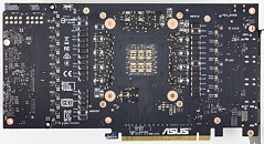
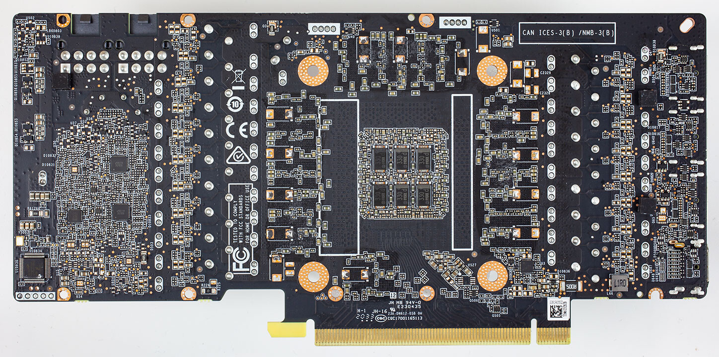
Another reason for this, according to Igor, is the actual "reference board" PG132 design, which is used as a reference, "Base Design" for partners to architecture their custom cards around. The thing here is that apparently NVIDIA's BOM left open choices in terms of power cleanup and regulation in the mounted capacitors. The Base Design features six mandatory capacitors for filtering high frequencies on the voltage rails (NVVDD and MSVDD). There are a number of choices for capacitors to be installed here, with varying levels of capability. POSCAPs (Conductive Polymer Tantalum Solid Capacitors) are generally worse than SP-CAPs (Conductive Polymer-Aluminium-Electrolytic-Capacitors) which are superseded in quality by MLCCs (Multilayer Ceramic Chip Capacitor, which have to be deployed in groups). Below is the circuitry arrangement employed below the BGA array where NVIDIA's GA-102 chip is seated, which corresponds to the central area on the back of the PCB.
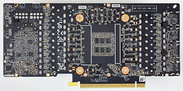
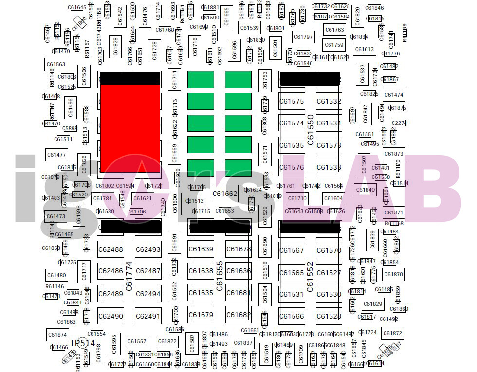
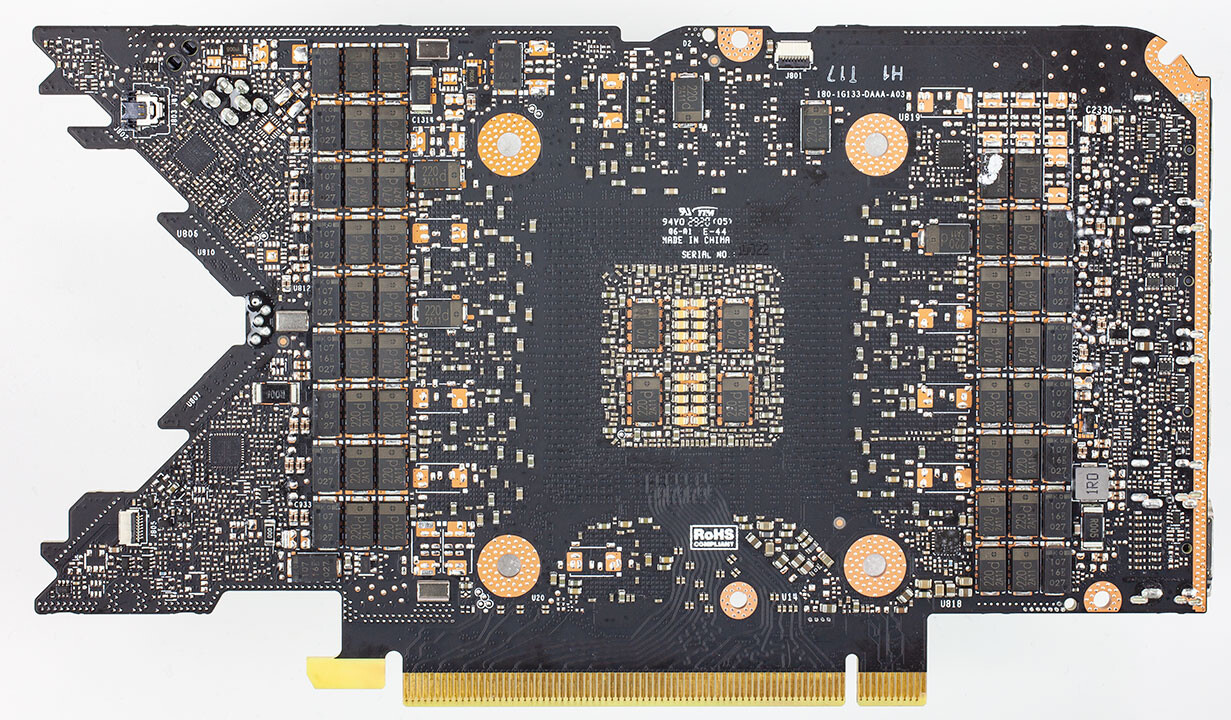
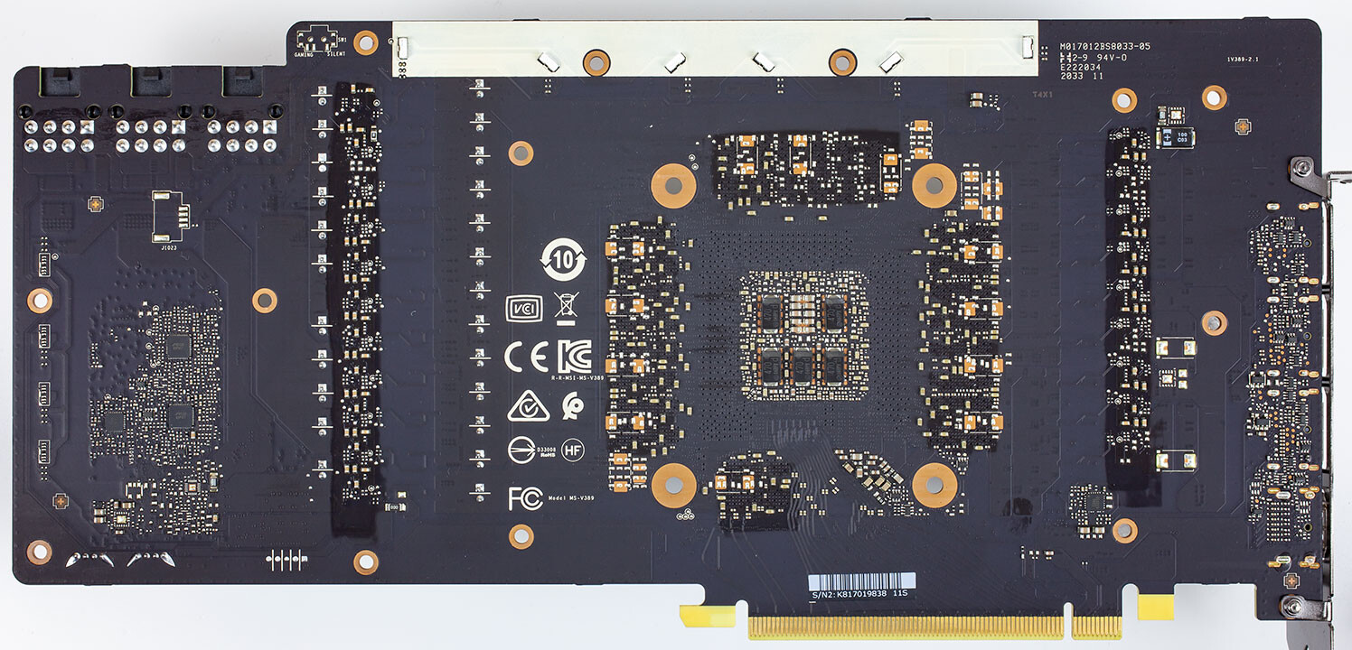
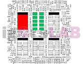 In the images below, you can see how NVIDIA and it's AIBs designed this regulator circuitry (NVIDIA Founders' Edition, MSI Gaming X, ZOTAC Trinity, and ASUS TUF Gaming OC in order, from our reviews' high resolution teardowns). NVIDIA in their Founders' Edition designs uses a hybrid capacitor deployment, with four SP-CAPs and two MLCC groups of 10 individual capacitors each in the center. MSI uses a single MLCC group in the central arrangement, with five SP-CAPs guaranteeing the rest of the cleanup duties. ZOTAC went the cheapest way (which may be one of the reasons their cards are also among the cheapest), with a six POSCAP design (which are worse than MLCCs, remember). ASUS, however, designed their TUF with six MLCC arrangements - there were no savings done in this power circuitry area.
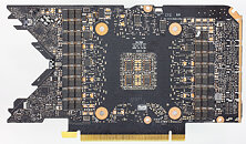

It's likely that the crash to desktop problems are related to both these issues - and this would also justify why some cards cease crashing when underclocked by 50-100 MHz, since at lower frequencies (and this will generally lead boost frequencies to stay below the 2 GHz mark) there is lesser broadband frequency mixture happening, which means POSCAP solutions can do their job - even if just barely.
Source:
Igor's Lab
Another reason for this, according to Igor, is the actual "reference board" PG132 design, which is used as a reference, "Base Design" for partners to architecture their custom cards around. The thing here is that apparently NVIDIA's BOM left open choices in terms of power cleanup and regulation in the mounted capacitors. The Base Design features six mandatory capacitors for filtering high frequencies on the voltage rails (NVVDD and MSVDD). There are a number of choices for capacitors to be installed here, with varying levels of capability. POSCAPs (Conductive Polymer Tantalum Solid Capacitors) are generally worse than SP-CAPs (Conductive Polymer-Aluminium-Electrolytic-Capacitors) which are superseded in quality by MLCCs (Multilayer Ceramic Chip Capacitor, which have to be deployed in groups). Below is the circuitry arrangement employed below the BGA array where NVIDIA's GA-102 chip is seated, which corresponds to the central area on the back of the PCB.


297 Comments on RTX 3080 Crash to Desktop Problems Likely Connected to AIB-Designed Capacitor Choice
www.techpowerup.com/249603/nvidia-confirms-issues-affecting-early-production-run-of-geforce-rtx-2080-ti-graphics-cards
I Will wait and see how this turns out, before ordering a card. But it does look very plausible that the problem is likely the capacotators with all these different layouts. This also truly shows who is the cheap ass manufacturer and who is more seriously. MSI surprised me while gigabyte and zotac disappointe on the capasitator layout.
It looks like as well Jay is right on asus tuf. It does have the more expensive capasitator layout for all six places.
From another side. Knowing what Jay just told. This looks really good for asus tuf card.
I Will wait and see the capacitator layout on evga FTW 3 card, before I decide. Else it looks like asus tuf card really is the go to card. Runs cool, has one the highest power target (at least for the cheaper cards at 375 watts), cooler design is great and it now also seems capasitator layout is one of the best to so far.
EDIT: And as someone else pointed out, eventually somebody would still get the shitty cards, so there is no escaping it.
www.asus.com/Graphics-Cards/ROG-STRIX-RTX3080-O10G-GAMING/specifications/
I'm not the sharpest tool in the shed, but they sometimes beat me to it and it is discouraging to see the same sort of journalistic censure somebody someone, you know who, demands from launch date ndas directed towards community forums.
POSCAP vs MLCC vs Aluminum or whatever is a very technical choice. At first you think its simple: just pick the thing with the lowest ESR and highest Capacitance, but then you start worrying about high-frequency operation (these GPUs are at 2GHz+ now). But not only that, there's temperature and more.
The article oversimplifies:I haven't done this stuff since I was in college. But what I do remember was pouring over capacitor spec sheets and tearing my head out trying to understand the nuanced differences between them. Just picking an MLCC capacitor series alone requires going through a giant 100+ page list, focusing on the Thermal, Frequency, Capacitance, and Resistance of your application.
"POSCAP is worse than MLCC" ?? Wut? I'm sure an 8-terminal low-inductance MLCC is superior to most others, but a cheap general-purpose MLCC may be worse. Its not like all MLCCs are made the same. Even then, "worse" in what way? POSCAPs don't lose capacitance at higher temperatures, while MLCCs are temperature-dependent and voltage-dependent (the higher the voltage and higher the temperature, the less capacitance you get).
Maybe the MLCC is better if you've found a section of the board that has superior heat-sinks / cooling, but maybe POSCAP gets better if you're in a warmer area and/or higher voltage. Like, this crap is devilishly complicated.
Heck: Even simplifying the discussion to ESR and Capacitance (ESR bad, Capacitance Good) you get utterly borked if you randomly get resonance for some stupid reason (where voltage/current "bounces" between two components, because by luck would have it... something is "ringing" at the same frequency as your capacitor). So maybe a higher ESR chip is better in those weird cases.
----------------
I'm sure someone out there made a mistake with capacitor selection. This is a very difficult part of high-speed electronics design. However, simplifying the discussion to "X design has 6-MLCC capacitors vs Y Design has POSCAPs" is completely useless. That level of discussion is insufficient to seriously understand the power issues going on at the sub-nanosecond scale (2GHz == 0.5 nanoseconds).
At the end of the day, you blackbox the entire decision tree and test the heck out of the electronics. If this does end up to be a capacitor issue, then it was a testing issue. Having to go under several board revisions to fix capacitor issues is like, standard EE-issues (like finding a bug in a version of the a computer program and having to issue a patch to fix it later). Your engineers are going to make that mistake, and you hope that your testing mechanisms are good enough to catch them.
----------
If anyone thinks that this job is easy, go to Murata's simsurfing site and browse around for a few minutes. That's one company's capacitor selection, mostly MLCCs. Then go to Panasonic's website, download their Capacitor tool, and search their database for POSCAPs. Then download everyone's pSpice models, and run a few simulations on LTSpice (its a free tool, you can do all of this for free).
:toast: